Alvarado SU5000 User manual

Alvarado Manufacturing Company, Inc.
12660 Colony Street, Chino, CA 91710
Phone: +1 (909) 591-8431
Fax: +1 (909) 628-1403
www.alvaradomfg.com
PUD3667R1-6
SUPERVISOR 5000
(SU5000)
Optical Turnstile with Bi-directional Motorized Barriers
Installation Instructions

Supervisor 5000 Installation Instructions
Contents. ......................................................................................................................................................................... 2
ETL Certication. ............................................................................................................................................................. 2
Safety Precautions. ......................................................................................................................................................... 3
Safety Icons..................................................................................................................................................................... 3
Installation Tools. ............................................................................................................................................................. 4
Uncrating. ........................................................................................................................................................................ 4
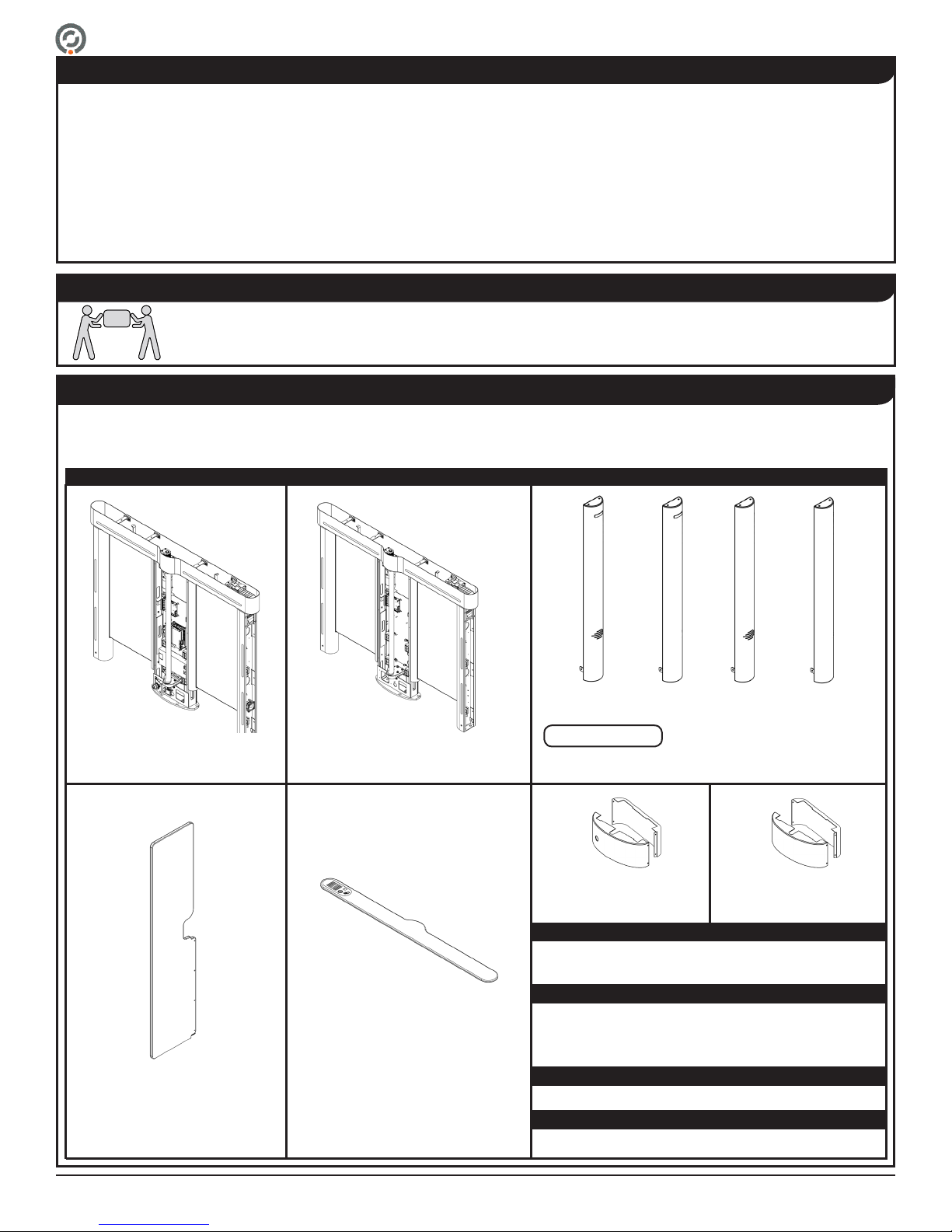
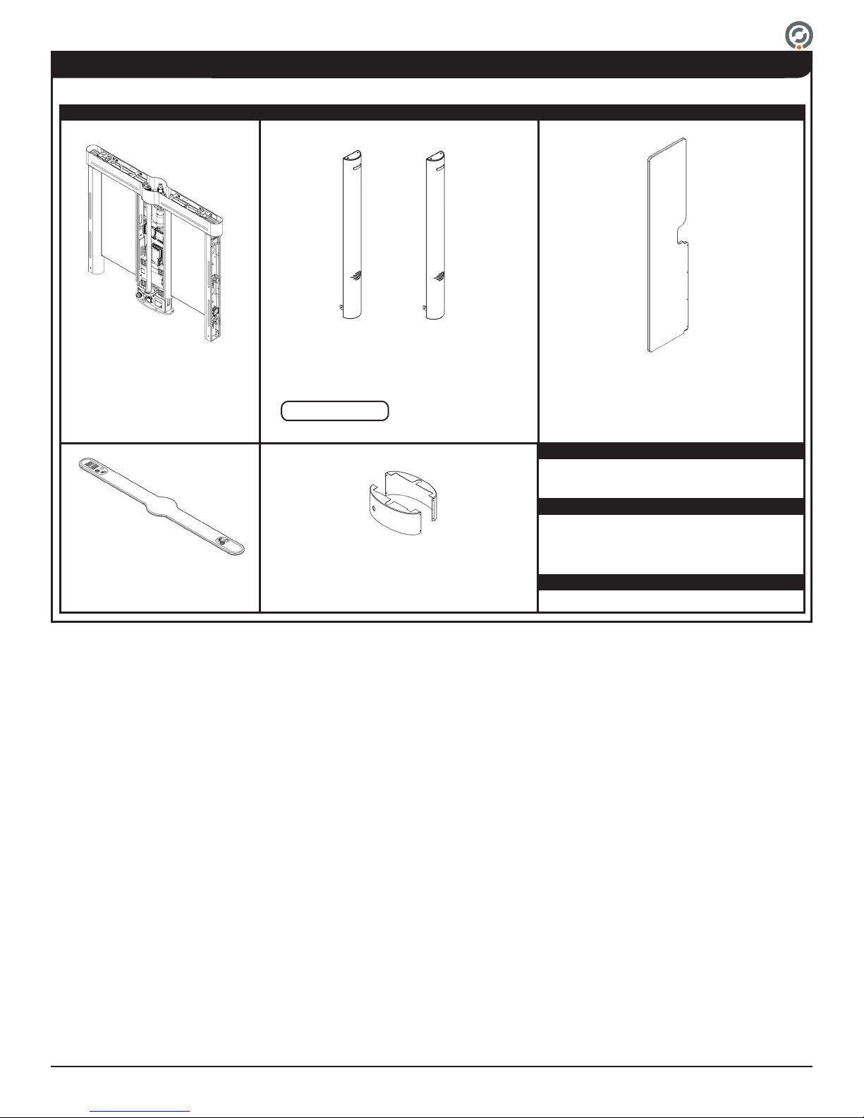
Parts List.......................................................................................................................................................................... 4
Introduction...................................................................................................................................................................... 6
Before You Begin............................................................................................................................................................. 8
Slab Requirements. .................................................................................................................................................. 8
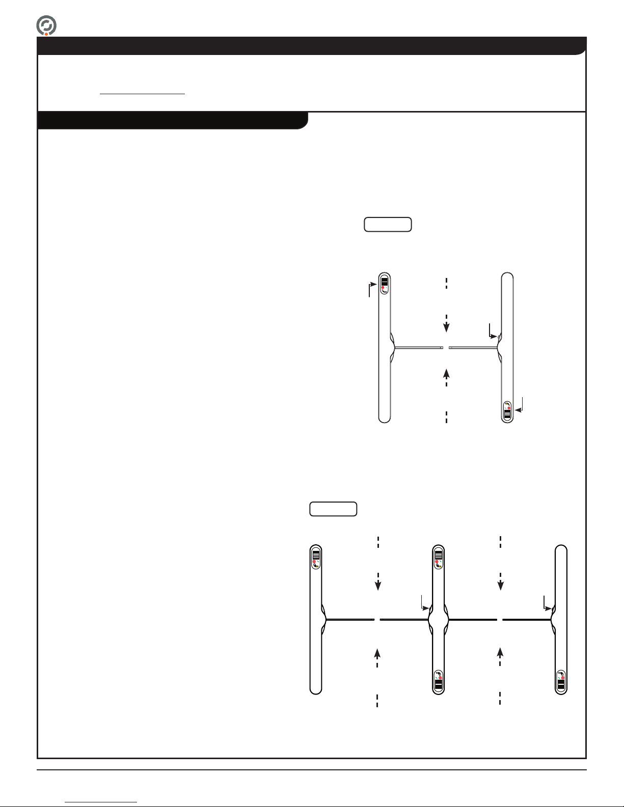
Space Requirements. ............................................................................................................................................... 8
Conduit Requirements. ............................................................................................................................................. 9
Electrical Requirements. ........................................................................................................................................... 9
Environmental Requirements.................................................................................................................................... 9
Communication Requirements................................................................................................................................ 10
Internal Card Reader Installation Requirements (Optional). ................................................................................... 10
Barcode Reader Requirements (Optional).............................................................................................................. 10
User Training........................................................................................................................................................... 10
Pre-Installation Checklist. ....................................................................................................................................... 10
Pre-Installation Instructions. ...........................................................................................................................................11
Cabinet Panel Removal. ..........................................................................................................................................11
QA Checkpoint Shim Removal.................................................................................................................................11
Baseplate Installation (Optional). ............................................................................................................................ 12
Installation Instructions.................................................................................................................................................. 13
Anchoring the Turnstile. .......................................................................................................................................... 13
End Cover Installation............................................................................................................................................. 14
Internal Card Reader Installation. ........................................................................................................................... 15
Wiring Instructions......................................................................................................................................................... 16
Primary Power......................................................................................................................................................... 16
Crossover Cable Connection. ................................................................................................................................. 16
I/O Control Board (13-0328 Rev. F). ....................................................................................................................... 17
Conguring Passage Modes. ........................................................................................................................................ 19
Ethernet Communication (Optional). ............................................................................................................................. 21
Barrier Installation.......................................................................................................................................................... 21
Post-Installation Functions Check. ................................................................................................................................ 23
Finish the Installation..................................................................................................................................................... 28
Cabinet Lid Installation............................................................................................................................................ 28
Cabinet Panel Installation. ...................................................................................................................................... 29
Base Cover Installation. .......................................................................................................................................... 29
Post-Installation Checklist. ............................................................................................................................................ 30
Troubleshooting............................................................................................................................................................. 31
Appendix A - Setting the Home Position........................................................................................................................ 32
Appendix B - 36" Single Lane - Plan, Elevation & Footprint Drawing............................................................................ 33
Appendix C - 28" & 36" Baseplate Dimensions. ............................................................................................................ 34
Appendix D - External DC Power Supply Installation (Optional). .................................................................................. 35
Appendix E - Multi-Lane Conduit Requirements. .......................................................................................................... 40
Appendix F - Crossover Cable Connection Diagrams................................................................................................... 41
Revision History............................................................................................................................................................. 42
Contents
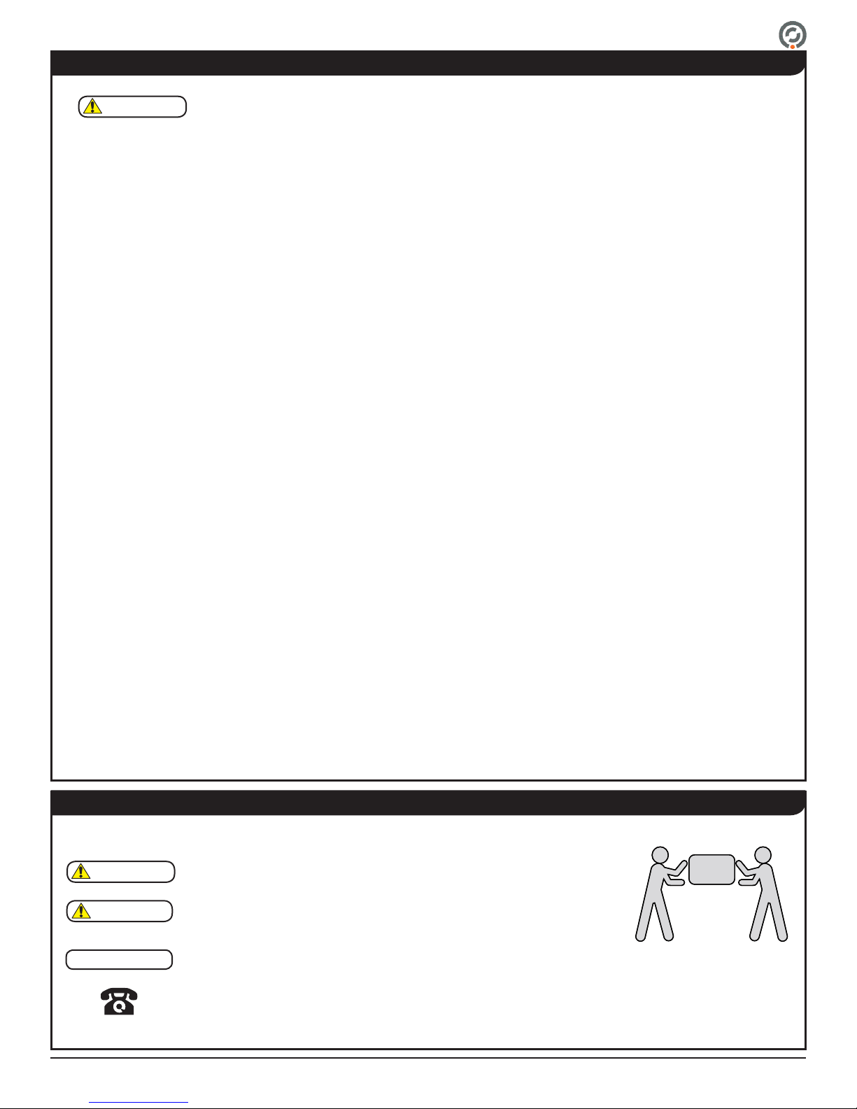
This product is fully certied by a nationally recognized testing laboratory to UL 2593 and
CSA C22.2 #247. Unauthorized modication to this product in any way is prohibited.
ETL Certication

Supervisor 5000 Installation Instructions
The following symbols are used throughout the manual to highlight important information and
potential risks when installing, servicing or using the turnstiles covered in this manual.
This symbol is used in this manual to warn installers and operators of
potential harm. Please read these instructions very carefully.
This symbol is used in this manual to designate potential conditions that
may pose a risk to pedestrians, personnel, property and equipment. Please
read these instructions very carefully.
NOTE This symbol is used in this manual to designate useful information for the
installer and operator. Please read these instructions.
For questions, please contact Alvarado at (909) 591-8431, Monday – Friday
7:00am to 4:30pm PST. Please read this manual completely before
installing or operating the purchased product.
Safety Icons
A minimum of two people
is required to complete
the installation of this
product.
The Supervisor 5000 may present a risk to persons and property if it is not installed and/or operated
correctly. This manual must be read in its entirety and all safety and operations information must be
folloed. Note the following precautions:
• For indoor use only.
• Use only skilled individuals to install and service the turnstile.
• DO NOT operate the turnstile if it has been damaged in any manner. If damaged, have the unit repaired or adjusted by a
skilled service person before use.
• DO NOT modify or alter the turnstile.
• Have skilled individuals maintain the turnstile according to a proper maintenance schedule.
• In access control applications, train all personnel that will be using the turnstile in the proper method of operation. In
addition, properly train new users as they are added to the system.
• DO NOT use non-Alvarado parts to repair a damaged turnstile.
• Closely follow the handling instructions for moving or lifting the turnstile during installation.
• Power o the turnstile before connecting or disconnecting any communication or power wiring to the turnstile.
• Pour utilisation à l'intérieur seulement.
• Utilisez uniquement des personnes qualiées pour installer et entretenir le tourniquet.
• NE PAS faire fonctionner le tourniquet s'il a été endommagé de quelque façon. S'il est endommagé, faire réparer ou
ajuster l'unité avant l'utilisation par un(e) préposé(e) à l'entretien qualié(e).
• NE PAS modier ou altérer le tourniquet.
• Le tourniquet doit être maintenu selon un calendrier d'entretien adéquat par des personnes qualiées.
• Dans les applications de contrôle d'accès, former tout le personnel qui utilisera le tourniquet selon la bonne méthode de
fonctionnement. De plus, bien former les nouveaux utilisateurs à leur intégration au système.
• NE PAS utiliser des pièces ne provenant pas du Alvarado pour réparer un tourniquet endommagé.
• Suivez strictement les instructions de manutention pour déplacer ou soulever le tourniquet lors de l'installation
• Éteignez le tourniquet avant de brancher ou de débrancher le câblage de communication ou le câblage d'electricité.
• This turnstile can be used by children aged 12 years and above, and persons with reduced physical, sensory or mental
capabilities or lack of experience and knowledge, if they have been given supervision or instruction concerning use of the
turnstile in a safe way and understand the hazards involved. Children shall not play with or around the turnstile.
• The turnstile shall be disconnected from its power source during service and when replacing parts. The turnstile shall be
disconnected from its power source before connecting or disconnecting any communication or other activation/feedback
control wires. If it is not possible that the technician can check from any point to which he has access that the main power
is removed, a disconnection with a locking system in the isolated position shall be provided.
Safety Precautions
CAUTION
WARNING
WARNING

Supervisor 5000 Installation Instructions
Installation Tools
• Tape Measure
• Chalk Line
• Pencil
• Hammer Drill
• 5/8" Concrete Drill Bit
• Shop Vac
• Hammer
• 3/32" Allen Wrench
• 9/16" Wrench
• Torque Wrench (ft-lbs.)
• Torque Wrench (in-lbs)
• 9/16" Socket
• Level
• 5/32" Allen Wrench
• #2 Phillips Head Screwdriver
• Precision Flat Head Screwdriver
• M4 'Stubby' Allen Wrench
(Supplied)
• Clear RTV Silicone
This product is shipped with all installation hardware and components. If installing a single lane, refer to the Single Lane Parts List
below. For additional lanes, refer to the Center Cabinet Parts List. Make sure that none of these parts are missing and/or damaged
before beginning installation. If parts are missing and/or damaged, please contact Alvarado.
End covers ship taped to the turnstile cabinets.
(Barrier height and width may vary.)
Single Lane Parts List
Concrete Anchor Package:
Hardware:
Cabling:
Software:
Parts List
Uncrating
• ⅜" x 2½" Hex Head Cap Screws (Qty 16)
• Barrier Clamp Bar Screws (Qty 8)
• ⅜" Flat Washers (Qty 16)
• ⅜" x 2" Concrete Anchors (Qty 16)
• Barrier Clamp Bars (Qty 2)
• 8' Crossover Cable (Qty 1)
• File Management CD (Qty 1)
The SU5000 has been packed for shipping to prevent damage to the unit. Two or more installers are required
to unload the SU5000 at the installation site. Once the turnstile cabinets have been placed in the installation
location, carefully remove the protective packing material from the sides of the cabinets.
Master Cabinet
(Qty 1) Slave Cabinet
(Qty 1)
End Covers
(Qty 4)
Barriers
(Qty 2) Cabinet Lids
(Qty 2)
Master Cabinet Base Cover
(Qty 1)
Slave Cabinet Base Cover
(Qty 1)
NOTE

Supervisor 5000 Installation Instructions
Center Cabinets are used to create additional lanes for multi-lane congurations. Each additional lane includes the parts below.
Cabling:
• 8' Crossover Cable (Qty 1)
End covers ship taped to the turnstile cabinets. (Barrier height and width may vary.)
Center Cabinet Parts List (Per Center Cabinet)
Concrete Anchor Package:
Hardware:
Parts List (cont.)
• ⅜" x 2½" Hex Head Cap Screw (Qty 8)
• Barrier Clamp Mounting Screws (Qty 8)
• ⅜" Flat Washers (Qty 8)
• ⅜" x 2" Concrete Anchors (Qty 8)
• Removable Barrier Clamps (Qty 2)
Center Cabinet
(Qty 1)
End Covers
(Qty 2)
Barriers
(Qty 2)
Center Cabinet Lid
(Qty 1)
Center Cabinet
Base Cover
(Qty 1)
NOTE

Supervisor 5000 Installation Instructions
Introduction
This manual covers the physical installation process for SU5000 Optical Turnstiles. A separate SU5000 User Guide provides
operating instructions and additional information such as conguring turnstiles for bi-directional passage applications and monitoring
outputs. It is highly recommended that both this manual and the SU5000 User Guide be read in their entirety prior to beginning
installation.
There are three types of SU5000 cabinets used to create passage lanes: a master cabinet, a slave cabinet, and a center
(expansion) cabinet. A single passage lane consists of a master cabinet and a slave cabinet [Figure 1A]. The center cabinet is used
to create additional passage lanes with the addition of a single cabinet [Figure 1B].
Each cabinet has an unsecured and secured side. Alvarado follows what we call the “right-hand rule." User status displays and card
readers are always installed on the right-hand side as you enter the turnstile.
SU5000 Cabinets
The center portion of the master cabinet contains the main
turnstile controller, I/O control board, motor and motor control
board, power supply, safety sensor receivers, one moving
barrier, and a power switch located at the base on the secured
side.
The top channel of the master cabinet contains the operational
sensor receivers, a drive system, and a user status display that
communicates lane status to the user. A card reader is normally
installed during installation underneath the lid below the user
status display.
Center cabinets contain both master and slave components.
Center cabinets are extension cabinets used in multi-lane
applications. An unlimited number of center cabinets can be
added.
The center portion of the center cabinet contains the main
turnstile controller, I/O control board, two motors and two
motor control boards, power supply, safety sensors for both
the master and slave side of the center cabinet, two moving
barriers, and a power switch located at the base on the
secured side of the master side.
The top channel of the center cabinet contains master and
slave side operational sensors, two drive systems, and two
user status displays that communicate lane status to the user.
Two card readers are normally installed during installation
underneath the lid below the user status display on both sides
of the center cabinet top channel.
The center portion of the slave cabinet contains a motor and
motor control board, safety sensor transmitters, and one
moving barrier.
The top channel of the slave cabinet contains the operational
sensor transmitters, a drive system, and a user status display
that communicates lane status to the user. A card reader is
normally installed during installation underneath the lid below
the user status display.
Master Cabinet
Center Cabinet (Multi-Lane Conguration)
Slave Cabinet
Fig. 1A Single-Lane Conguration
Multi-Lane Conguration
Fig. 1B
Secured Side
Unsecured Side
Slave
Cabinet Center
Cabinet
Master
Cabinet
Secured
Side
Unsecured Side
Slave
Cabinet Master
Cabinet
Power
Key
Switch
User
Status
Display
User
Status
Display
Power
Key
Switch
Power
Key
Switch
Master
Side
Slave
Side
Entry
Direction
Entry
Direction
Entry
Direction
Exit
Direction
Exit
Direction
Exit
Direction

Supervisor 5000 Installation Instructions
Passage Lane Width
Fig. 3
36" Passage Lane
28" Passage Lane
36.0
2.0
(51) (51) (432)
(914)
(330)
(711)
2.0
13.0 17.0
28.0
SU5000 barriers come in widths to create 28" or 36" passage lanes [Figure 3].
SU5000 barriers come in low (35"), mid (46") and full (69") heights [Figure 2].
Barrier Height
Barrier Heights
Passage Lane Widths
Fig. 2
Full Height BarrierMid Height Barrier
Low Height Barrier
69.0
(1752)
46.0
(1168)
6.0
6.0 (152)
35.0
(889)
Access Control Integration
Single passage activation and the various other inputs and outputs available to / from the SU5000 are accessed through the I/O
control board located in the master cabinet. The required system input is a voltage-free, momentary dry contact. Outputs are also
provided in this form. In rare cases, depending on the access control system, it may be desirable to utilize isolation relays to ensure
proper system signaling. Additional information on I/O interfacing is provided later in this manual.
For select projects, a TCP/IP interface is available. This interface allows a third party access system to communicate to / from
the SU5000 using a dened TCP/IP command structure. There is an additional charge for implementation and use of the TCP/IP
interface and implementation requires programming eorts on the part of the access system provider. Instructions pertaining to the
TCP/IP interface is outside the scope of this manual.
There are two types of interfaces to allow an access control system to operate with the SU5000:
Dry Contact
TCP/IP
Network Communication
SU5000 turnstiles are TCP/IP enabled. Running Ethernet cabling to the SU5000 provides a number of benets. (1) It allows
implementation of Alvarado’s TCP/IP control and monitoring software. (2) It allows easy implementation of SU5000 application
software updates and enhancements. If the SU5000s are networked, updates can be installed over the network. (3) Alvarado has
future plans to further develop the TCP/IP capabilities of the SU5000. The benets of this future development can only be realized
if the turnstiles are networked.
6.0 (152) 6.0 (152)

Supervisor 5000 Installation Instructions
Before You Begin
Use only skilled technicians for site preparation and installation of the turnstile using Alvarado’s instructions.
Refer to the footprint and plan drawings [Figure 4 & 5] to determine the installation location and conduit requirements for a 28"
single lane. See Appendix B for 36" width.
For ease of installation and service, allow 6" of space between cabinets and walls or other surfaces.
The following slab requirements must be taken into consideration when selecting the installation location:
• A level solid concrete pad with a minimum thickness of 4" (102mm).
• Use full sweep electrical conduit underneath the oor.
• Three separate conduits for primary source power, external data, and the crossover cable must be used.
• Cabinets must be installed plumb with the oor while level and square to each other.
Plan View Elevation View
Footprint Drawing
Fig. 4 28" Single Lane - Plan, Elevation & Footprint Drawing
NOTE
AREA FOR CONDUIT
THRU ALL THRU ALL
13.0
39.1
28.0
52.4
35.0
2.0
6.0
1.9
1.3
1.3
2X
2X
2X
2X
2X 3X .6 .6
(15) (15)
.9
.7
23.4
23.4
6.3
3.3
2.6
0
3.3
6.3
.9
5.8
4.3
(51)
(152)
(48)
(33)
(33)
(23)
0
(18)
(594)
(594)
(160)
(84)
(66)
(84)
(160)
(23)
(147)
(109)
(330)
(993)
(711)
(1331)
(889)
Slab Requirements
Space Requirements
(889) (1041)
35.0 41.0

Supervisor 5000 Installation Instructions
Seal the oor area around the conduits running up and
into the cabinets. This will prevent condensation and
debris build-up coming from whatever may be below
the oor.
Environmental Requirements
Conduit Requirements
• DO NOT install the product outdoors. This product is intended for indoor use only.
• DO NOT install the SU5000 where infrared lighting (strobe lights, ash photography, etc.) is in the direct path of the
optical sensors. Interference may aect the performance of the turnstile.
The following are suggested operating temperature and humidity ranges for the SU5000:
Operation Non-Operation/Storage
Temperature Range 10-32°C / 50-90°F 0-40°C / 32-104°F
Humidity Range (Non-Condensing) 15% - 85% RH --
Power Supply 110-120 VAC, 60 Hz or 220/240 VAC, 50 Hz
Power Requirements Peak power consumption is 300W per lane with all options installed
Operational Voltage Primary power is stepped down and rectied for low-voltage 24 VDC, 12 VDC,
and 5 VDC operation
Fuse 2.5A (slo-blo) located in the master cabinet
Drive Motor 24 VDC (brushless)
Surge Protection Alvarado suggests the use of surge protection on the high-voltage power line to
further protect electronics
Operating the SU5000 outside the listed temperature and humidity ranges may negatively aect turnstile
performance, and could potentially cause damage to the turnstile and void the warranty.
Fig. 5 SU5000 Conduit Lines
NOTE
Electrical Requirements
CAUTION
Symbology Description Conduit Size
Primary
Power**
3/4”
Access Control /
Ethernet
3/4”
Access
Control
3/4”
Crossover
Cable
1.5”
The opening for the conduit in the center of each cabinet
is 6.50” x 2.50” (165mm x 64mm). The three required
conduits MUST t in this area [Figure 5].
For multi-lane conduit requirements, refer to
Appendix E on Page 39.
**If the External DC Power Supply option was ordered,
use this conduit to route 24VDC.
NOTE
NOTE

Supervisor 5000 Installation Instructions
Communication Requirements
Internal Card Reader Installation Requirements (Optional)
Barcode Reader Requirements (Optional)
User Training
Pre-Installation Checklist
Signal Inputs and Outputs To / From Access Control System
Inputs - Signal inputs from outside systems are wired into the SU5000’s I/O control board. There are two types of input
signals, momentary dry contacts (MDC) and sustained dry contacts (SDC). All input signals must be normally open, voltage-
free, dry contacts, with the exception of the re alarm input, which can be congured (via jumper on the I/O control board) to
accept either a normally open or normally closed sustained contact. MDC’s must be at least 100ms in duration to register.
While the SU5000 can accept signals up to 2 seconds in duration, the suggested MDC input duration is 1 second or less to
support rapid throughput in high volume applications.
Outputs – Signal outputs are available from the SU5000’s I/O control board. Outputs are normally open, voltage-free,
momentary dry contacts. The output signal length is 500ms in duration.
Inability to Provide Specied Inputs - If the access system cannot provide the specied MDCs, isolation relays should be
used. NEVER connect signal lines containing voltage directly to the I/O control board.
Network Communication
A networked PC with Alvarado's TCP/IP control and monitoring software is required. Adhere to IEEE standards for network cabling
requirements.
It is the installer's responsibility to ensure the following steps are completed before beginning the installation.
Card readers or other physical access devices may be installed under the top channel lid on either or both right-hand sides of the
turnstile. Card readers / physical access devices are not supplied by Alvarado. Due to the slim prole of the SU5000, generally only
mullion-sized card readers can be installed inside the cabinet.
The physical dimensions of the card reader cannot exceed: 1.00" H x 1.90" W x 6.50" D (25mm x 48mm x 165mm).
All personnel that will be involved with operating the SU5000 should be trained in the proper method of operation. Detailed
operation instructions are outside the scope of this manual, but can be found in the SU5000 User Guide (also included with the
product). If further training is desired, contact Alvarado for information regarding on-site training services.
At least two weeks prior to shipment, provide Alvarado with sample media of the exact size and type that will be scanned by the
barcode reader. A sample of EVERY type of media that you expect to validate should be provided. Samples provided to Alvarado
must be IDENTICAL (i.e., material, size, color, etc.) to the barcode media that will be used in the application.
Barcode colors and spacing matter in how well the bar codes read. In order for a barcode symbol to be recognized, there must be
an adequate contrast between the dark bars and the light spaces. For best readability, follow the standard color combinations. A
black barcode on a white background is always best.
An optional 1D/2D barcode reader can be factory supplied and installed to either or both right-hand legs of the turnstile. The barcode
reader specications are listed below.
• Imager: Honeywell 3310g Area Imager
• Communication: RS232 Serial
• Optional Communication: Wiegand (Using an RS232 Serial to Wiegand converter)
• Recommended Barcode Symbology: Code128 or Interleaved 2 of 5 for 1D barcodes; DataMatrix for 2D symbology
• Size of Open Scan Area: 2.25" W x 1.00" D (57mm x 25mm)
• Maximum Barcode Reading Area on Card or Pass: 2.00" W x .75" D (51mm x 19mm)
• Maximum Distance of Barcode from Leading Edge of Card or Pass: 1.00" D (22mm)
NOTES
1. All components and hardware to be installed have been unpacked, correctly identied, and moved to the installation location.
2. The turnstile conguration and layout has been conrmed with the site manager.
3. All applicable requirements in the Before Getting Started section have been met.

Supervisor 5000 Installation Instructions
Cabinet Panel Removal
QA Checkpoint Shim Removal
It is assumed that the Pre-Installation Checklist steps are complete.
As part of our QA process, orange-colored shims
are inserted to set the correct gap for the electro-
mechanical brake. Remove these shims BEFORE
powering on the turnstile.
There is one (1) motor shim located in the master
cabinet; one (1) motor shim located in the slave
cabinet; and two (2) motor shims located in the center
cabinet (if applicable).
1. Remove each shim after the cabinet panel has
been removed by pulling rmly on the orange pull-
tab [Figure 7].
IMPORTANT
Pre-Installation Instructions
Cabinet Panel
Motor
Shim
(1 per motor)
Orange
Pull-Tab
Mounting Screws
1. Using a Phillips screwdriver, remove the six (6) mounting
screws that secure the cabinet panel to the master cabinet
[Figure 6]. Do not discard the cabinet panel screws as they
will be reused.
2. Once the screws are removed, gently slide the cabinet
panel out of position and set the panel o to the side
[Figure 6].
3. Repeat steps 1 and 2 to remove the slave cabinet panel.
Fig. 6
Fig. 7
Removing Screws
Removing Motor Shims
NOTE

Supervisor 5000 Installation Instructions
NOTE
Baseplate Installation (Optional)
Refer to Appendix C on Page 34 for 28" and 36" baseplate dimensions.
The baseplate enables installation of the SU5000 turnstile on a solid foundation without the need to drill holes into the concrete.
The baseplate also provides concealed conduit channels for wiring primary power, crossover communication, and access control.
Baseplates may be bridged together for multi-lane congurations. The following information will guide the installer in baseplate
installation:
1. Determine and mark the installation location.
2. Place the baseplate in the marked location.
3. Determine how the primary power and access control wiring will be routed to the master and/or center cabinet. Most
commonly, the wiring is run into the baseplate through one of the side plates and routed to the master and/or center cabinet.
To remove the side plate, remove the four (4) screws as shown in [Figure 8].
4. Use the center cable channel to route the primary power, crossover cable, and access control wires as shown in [Figure 8].
5. Mount the SU5000 cabinets to the baseplate at the anchor location using the supplied mounting bolts [Figure 8].
6. For multi-lane applications, bridge the baseplates using the supplied bridge support(s) and screws [Figure 8].
7. Reinstall the side plate(s).
Fig. 8 Baseplate
Holes for bridging
multiple baseplates
Anchor locations
Conduit holes for power and communication cables
(Use separate conduits for power and communication cables)

Supervisor 5000 Installation Instructions
Installation Instructions
Anchoring the Turnstile
1. Place the master cabinet and the slave cabinet in the determined location [see dimensions - Figure 4].
2. All cabinets must be level and square to eachother. This will ensure that the optical sensors are aligned, and that the barriers
will line up properly when installed. Use the following procedures to level the cabinets, and square each cabinet with respect to
the oor and other cabinets:
A. Measure the distance from the inside wall of one cabinet
top channel to the inside wall of the other cabinet top
channel, on both the entry and exit side of the lane for a
consistent measurement [Figure 9A].
B. Measure the diagonal distance from the end of one
cabinet to the end of the opposing cabinet, then
measure the opposing diagonal distance [Figure 9B]. If
these distances are equal, the cabinets are square.
C. Using a level, verify each cabinet is level [Figure 9C]. If
necessary, shim to bring the cabinets level.
Fig. 9A
Fig. 9C
Fig. 9B
NOTE The lane 1 master cabinet is always the right-most cabinet in relation to the unsecured side.

Supervisor 5000 Installation Instructions
End Cover Installation
Anchoring the Turnstile (cont.)
3. Use a pencil and mark each mounting hole location
[Figure 10]. There will be a total of seven (7)
mounting holes per cabinet. Remove the cabinets
when complete.
4. Using a 5/8" concrete drill bit, drill the anchor holes
3" in depth at the center of each marked location.
The anchor holes must be clean before installing the
anchor bolts. If the holes are not clear of debris, the
anchor bolts may not tighten correctly.
5. Insert the anchors into each drilled hole [Figure 11].
The threaded end of the anchor must be inserted into
the hole rst. Use a hammer to tap the anchors into
place, if needed. Ensure that the anchors are ush
with the concrete oor.
6. If not already done, pull all wires (AC power, access
control and crossover cable) through conduit and
conduit access in center frame of cabinet prior to
anchoring cabinets.
7. Using clear RTV silicone, seal the gaps between the
conduit and conduit holes.
8. Maneuver each cabinet over the anchor locations.
Insert seven (7) 3/8" x 2-1/2" anchor bolts and at
washers.
9. Using a socket wrench and 9/16" socket, provisionally
snug the anchors. Do not fully tighten them yet.
The anchors are not torqued to specication yet, as the
turnstile may need shimming during the barrier leveling
procedure on Page 22. Torque anchors to 80 ft-lbs after
the barrier leveling procedure is completed.
The end covers are shipped loosely attached to the SU5000 with
the mounting hardware taped inside each cover.
1. Gently push the lower end [LOWER END - Figure 12] of the
end cover into place, aligning the mounting holes. Thread in
two mounting screws [Figure 12].
2. Push the rest of the end cover into place. Align the upper
end [UPPER END - Figure 12] mounting holes and insert the
remaining two mounting screws and tighten using a Phillips
screwdriver.
3. Using a 3/32"Allen wrench, tighten the lower mounting
hardware.
4. Repeat Steps 1 - 3 for all end covers.
Fig. 11
Fig. 10
Anchoring Holes
(7 total)
Concrete Anchor
Fig. 12
3/32" Allen
Wrench
Phillips
Screwdriver
UPPER END
LOWER END
NOTE
NOTE
NOTE
Marking Anchor Holes
Inserting Anchors
Installing End Covers
If installing an end cover that has a barcode reader installed, be
sure to connect the barcode reader communication cable to your
access control board before installing the end cover.
Anchoring Holes
(7 total)

Supervisor 5000 Installation Instructions
Internal Card Reader Installation
Removing Status Light Board
Mounting the Card Reader
Routing the Output Cable Routing the Output Cable
Output Cable
(to Access
Control
System)
Fig. 15A Fig. 15B
Mullion Style
Card Reader
1. Locate the card reader mounting bracket [Figure 13].
2. Using a Phillips head screwdriver, remove the status light board
[Figure 13].
3. Using a Phillips head screwdriver, remove the three (3)
mounting screws and remove the card reader mounting bracket.
4. Install the card reader per manufacturer's instructions.
If the distance between the installed card reader and top channel
lid exceeds the read range of the card reader, shims may be used
to elevate the card reader by a maximum of 3/8" (9.5mm). DO NOT
allow the card reader to touch the status light board.
5. Using a Phillips head screwdriver, insert and tighten three (3)
mounting screws that secure the mounting bracket.
6. Place the status light board over the mounting standos
and align the holes. Insert and tighten four (4) Phillips head
mounting screws [Figure 14].
7. Route the output cable through the turnstile and connect to your
access control system.
[Figure 15A & 15B].
Output cable must be routed down through the access hole.
When removing and reattaching the card reader mounting
bracket and status light board, make sure to re-seat and check
all wire harnesses for damage.
Fig. 14
Fig. 13
Mounting
Screws
Status Light
Board
Mounting
Bracket
Mounting
Standoff
Card Reader
Output Cable
Access Hole
Exit Hole
NOTES
NOTE
(Status Light Board wire
harnesses not shown)
(Status Light Board wire
harnesses not shown)
Card readers used in connection with the site access control system
are not included with the SU5000. The SU5000 has sucient area for
the installation of small mullion or slim style proximity card readers.
Most card readers do not require separate power inputs. In the event
that your reader requires a separate power input – do not pull this
power from the SU5000 power supply.
Due to the slim design of the SU5000, there is no space available to
install circuit boards or other equipment associated with the access
control system. Access control boards used in connection with the
SU5000 are installed in locations exterior to the SU5000, in a wiring
closet or other location.

Supervisor 5000 Installation Instructions
Center cabinets have two crossover cable connectors tucked
in the base: one labeled MASTER and one labeled SLAVE.
Crossover cables are used to interconnect master and slave
connectors. Refer to Appendix F for crossover cable connection
diagrams.
The included crossover cable interconnects communication signals
and low-voltage 24VDC between the master and slave cabinets.
The default length of the crossover cable included with the SU5000
is 8'. Optional crossover cable lengths of 20' and 40' are available.
1. Locate the low-voltage terminal block tucked in the bottom of
the base in the master cabinet [Figure 18].
2. Insert the 24VDC positive wire (orange) and the negative wire
(black) into the terminal block, matching the colors with the
other side and tighten [Figure 18].
3. Connect the data connector from the crossover cable to the
data connector in the master cabinet [Figure 18].
4. Repeat Steps 1 – 3 for the slave cabinet.
Wiring Instructions
IMPORTANT
110VAC and 220VAC primary power must be hard wired in
place. It is strongly recommended that a licensed electrician
perform this procedure in accordance with applicable local
codes.
The primary wiring lines for 110VAC and 220VAC consist of the
following:
Terminal 110V 220V
Neutral White Blue
Line Black Brown
Ground Green Green/Yellow
1. Locate the pre-installed power terminal block and attached
wiring (located next to the power key switch) [Figure 16].
2. Attach each power wire to the power terminal block with
the corresponding color exiting on the other side
[Figure 16 - 17].
3. Using a Phillips head screwdriver, tighten each terminal
block connection.
Data/Communication
Cable (tucked in the
bottom of the cabinet)
Fig. 18
L
N
G
L
N
G
Crossover Cable
(packaged separately)
24VDC Power and
Ground Wire (tucked in
the bottom of the cabinet)
220VAC
110VAC
Primary Power
NOTE
Crossover Cable Connection
FOR EXTERNAL DC POWER SUPPLY INSTALLATION
INSTRUCTIONS, REFER TO APPENDIX D ON PAGE 35.
NOTE
Power Terminal
Block
Power Key
Switch
Fig. 16
Fig. 17
Power Terminal
Block
Power Key
Switch

Supervisor 5000 Installation Instructions
I/O Control Board (13-0328 Rev. F)
Fig. 19
Fig. 19A
Master Cabinet
I/O Control Board (13-0328 Rev. F))
LEGEND
ITEM NAME
J1 Input Terminals
J2 Output Terminals
JP1 RS485 Termination Resistor
JP2 RS485 Termination Resistor
JP3 Fire Alarm System Jumper
(N.O. - N.C.)
S1 Entry Side Open Test Button
S2 Entry Side Reject Test Button
S3 Previous Sensor Group
S4 Next Sensor Group
S5 Exit Side Open Test Button
S6 Exit Side Reject Test Button
Signal Inputs and Outputs
To / From Access Control System
Inputs
Signal inputs from outside systems
are wired into the SU5000’s I/O control
board. There are two types of input
signals, momentary dry contacts (MDC)
and sustained dry contacts (SDC). All
input signals must be normally open
(N.O.), voltage-free, dry contacts, with
the exception of the re alarm input,
which can be congured (via jumper
on the I/O control board) to accept
either a normally open or normally
closed (N.C.) sustained contact. MDC’s
must be at least 100ms in duration to
register. While the SU5000 can accept
signals up to 2 seconds in duration,
the suggested MDC input duration
is 1 second or less to support rapid
throughput in high volume applications.
Outputs
Signal outputs are available from the
SU5000’s I/O control board. Outputs
are normally open, voltage-free,
momentary dry contacts. The output
signal length is 300ms in duration.
Inability to Provide Specied Inputs
If the access system cannot provide the
specied MDCs, isolation relays should
be used. NEVER connect signal lines
containing voltage directly to the I/O
control board.

Supervisor 5000 Installation Instructions
I/O Control Board (13-0328 Rev. F) Terminal Descriptions
J2 Output Contacts J1 Input Contacts
Pin # Pin
Name
Function
Description
Contact
Type
Function & Behavior
Description
Pin # Pin
Name
Function
Description
Contact
Type
Function & Behavior
Description
1 GNDX Ground N/A Common output signal
ground.
1 GND Ground N/A Common input signal ground.
2 ENTACX Authorized
Passage
Entry
MDC An output occurs when an
authorized entry passage is
completed.
2 ENTACC Good Card
Entry
MDC Opens the turnstile for one
authorized passage until
passage occurs or timeout.
3 ENTUCX Unauthorized
Passage
Entry
MDC An output occurs when an
unauthorized entry passage
is completed.
3 ENTREJ Bad Card
Entry
MDC Illuminates the entry side
RED User Status Icon for 2
seconds.
4 ENTALRX Unauthorized
Presence
Entry
MDC An output occurs when
there is entry into the lane
area from the entry direction
without authorization.
4 ENTPAS Free
Passage
Entry
SDC Sets the turnstile to Free
Passage mode in the entry
direction.
5 ENTCLSX N/A N/A Reserved 5 ENTCLS Close
Direction
Entry
SDC Sets the turnstile to No
Passage mode in the entry
direction.
6 EXTACX N/A N/A Reserved 6 ENTOVR Single
Override
Entry
MDC Opens the turnstile for one
authorized passage in the
entry direction independent
of the access control system.
(Typically used for button at
security desk.)
7 GNDX Ground N/A Common output signal
ground.
7 ENTSERVICE Visitor Mode SDC Places the turnstile in Free
Passage/Barrier Disabled
Mode in both the entry and
exit directions.
8 EXTACX Authorized
Passage Exit
MDC An output occurs when an
authorized exit passage is
completed.
8 GND Ground N/A Common input ground signal.
9 EXTUCX Unauthorized
Passage Exit
MDC An output occurs when an
unauthorized exit passage is
completed.
9 EXTACC Good Card
Exit
MDC Opens the turnstile for one
authorized passage until
passage occurs or timeout.
10 EXTALRX Unauthorized
Presence
Exit
MDC An output occurs when there
is entry into the lane area
from the exit direction without
authorization.
10 EXTREJ Bad Card
Exit
MDC Illuminates the exit direction
RED User Status Icon for 2
seconds.
11 EXTCLSX N/A N/A Reserved 11 EXTPAS Free
Passage
Exit
SDC Sets the turnstile to Free
Passage mode in the exit
direction.
12 EXTOVRX N/A N/A Reserved 12 EXTCLS Close
Direction
Exit
SDC Sets the turnstile to No
Passage mode in the exit
direction.
13 BLKSEN Blocked
Sensor
MDC An output occurs when
a sensor is blocked for a
dened length of time (default
15 seconds).
13 EXTOVR Single
Override
Exit
MDC Opens the turnstile for one
authorized passage in the
exit direction independent of
the access control system.
(Typically used for button at
security desk.)
14 SOUT-1 Free
Passage Exit
MDC An output occurs when there
is a activation in the exit
direction.
14 EXTSERVICE Horizontal
Arm
Breakaway
N/A Available on the SU3000 only.
15 GNDX N/A N/A Common output signal
ground.
15 GND Ground N/A Common input ground signal.
16 DHO Door Held
Open
MDC An output occurs when the
barriers remain open after
the allotted time to close
after passage (default 12
seconds).
16 N/O Normally
Open Mode N/A Not available on the SU5000.
17 BREAKAWAY Barrier
Broken Away
MDC An output occurs when the
barrier holding force has
been exceeded and the
barriers give way.
17 BARDISABLE Barrier
Disable
Mode
N/A Not available on the SU5000.
18 SOUT-2 Crawl Sensor N/A Not available on the SU5000. 18 EMROVR Emergency
Override
SDC
(N.O. or
N.C.)
Opens the barriers toward
the unsecured side; barriers
remain open and turnstile is
inactive until SDC is removed,
or contact is reestablished
if N.C. jumper is enabled.
(Typically used for re alarm
or life safety systems.)
19 SOUT-3 N/A N/A Reserved 19 SINPUT N/A N/A Reserved
20 GNDX Ground N/A Common output signal ground. 20 GND Ground N/A Common output signal ground.

Supervisor 5000 Installation Instructions
The SU5000 provides bi-directional access control in conjunction with a facility access control system. For bi-directional
applications, the entry and exit directions can be individually congured to dierent passage modes to suit facility requirements.
For example, a turnstile can be congured for Controlled Passage mode in the entry direction, and Free Passage mode in the exit
direction. SU5000 passage modes are described on Page 23. Further information on the smart use of passage modes can be
found in the SU5000 User Guide.
Turnstile passage modes can be congured in one of three ways:
I/O Control Board
Passage modes are set via wiring to the I/O control board inputs. This method is ideal for facilities that do not require changing
passage mode congurations throughout the day. This is the most common method used by our customers. Instructions for wiring
to the I/O control board are provided below.
Turnstile Lane Key Control
If this option has been ordered for your turnstiles, two 3-position key switches are installed on the turnstile. Turning the key to one
of the three positions allows each turnstile direction to be placed in any of the passage modes. Instructions on using lane key
control are provided on Page 26.
GateKeeper
GateKeeper is an optional desktop software application. GateKeeper, along with other functionality, allows the passage modes for
both the entry and exit side of the turnstiles to be changed. Instructions on conguring passage modes using GateKeeper is outside
the scope of this manual.
Conguring Passage Modes
Setting Controlled Passage Mode (I/O Control Board)
Entry Direction
Exit Direction
TO ACCESS
CONTROL
SYSTEM
TO ACCESS
CONTROL
SYSTEM
Entry Direction
1. Locate the access control system
leads used to indicate an authorized
passage in the entry direction is
allowed.
2. Connect leads to the ENTACC and
GND terminals on the I/O control
boards input terminal strip (J1)
[Figure 20].
Exit Direction
1. Locate the access control system
leads used to indicate an authorized
passage in the exit direction is
allowed.
2. Connect leads to the EXTACC and
GND terminals on the I/O control
boards input terminal strip (J1)
[Figure 20].
Fig. 20

Supervisor 5000 Installation Instructions
Setting Free Passage Mode (I/O Control Board)
Setting No Passage Mode (I/O Control Board)
Entry Direction
Exit Direction
Exit Direction
Entry Direction
Entry Direction
1. Locate the ENTPAS and GND
terminals.
2. Using a wire jumper, connect the
ENTPAS and GND terminals
[Figure 21].
Exit Direction
1. Locate the EXTPAS and GND
terminals.
2. Use a wire jumper to connect the
EXTPAS and GND terminals
[Figure 21].
Entry Direction
1. Locate the ENTCLS and GND
terminals.
2. Use a wire jumper to connect the
ENTCLS and GND terminals
[Figure 22].
Exit Direction
1. Locate the EXTCLS and GND
terminals.
2. Using a wire jumper, connect the
EXTCLS and GND terminals
[Figure 22].
Fig. 21
Fig. 22
Other manuals for SU5000
1
This manual suits for next models
1
Table of contents