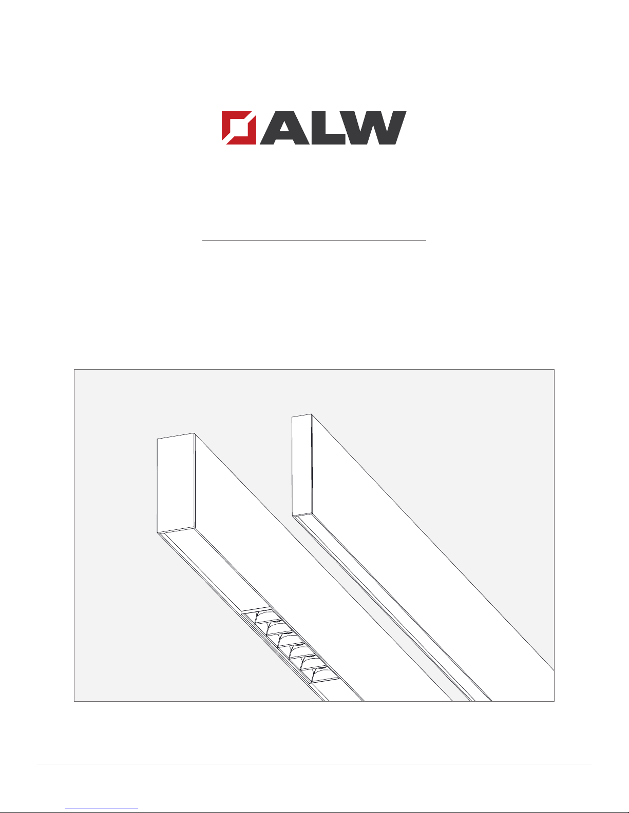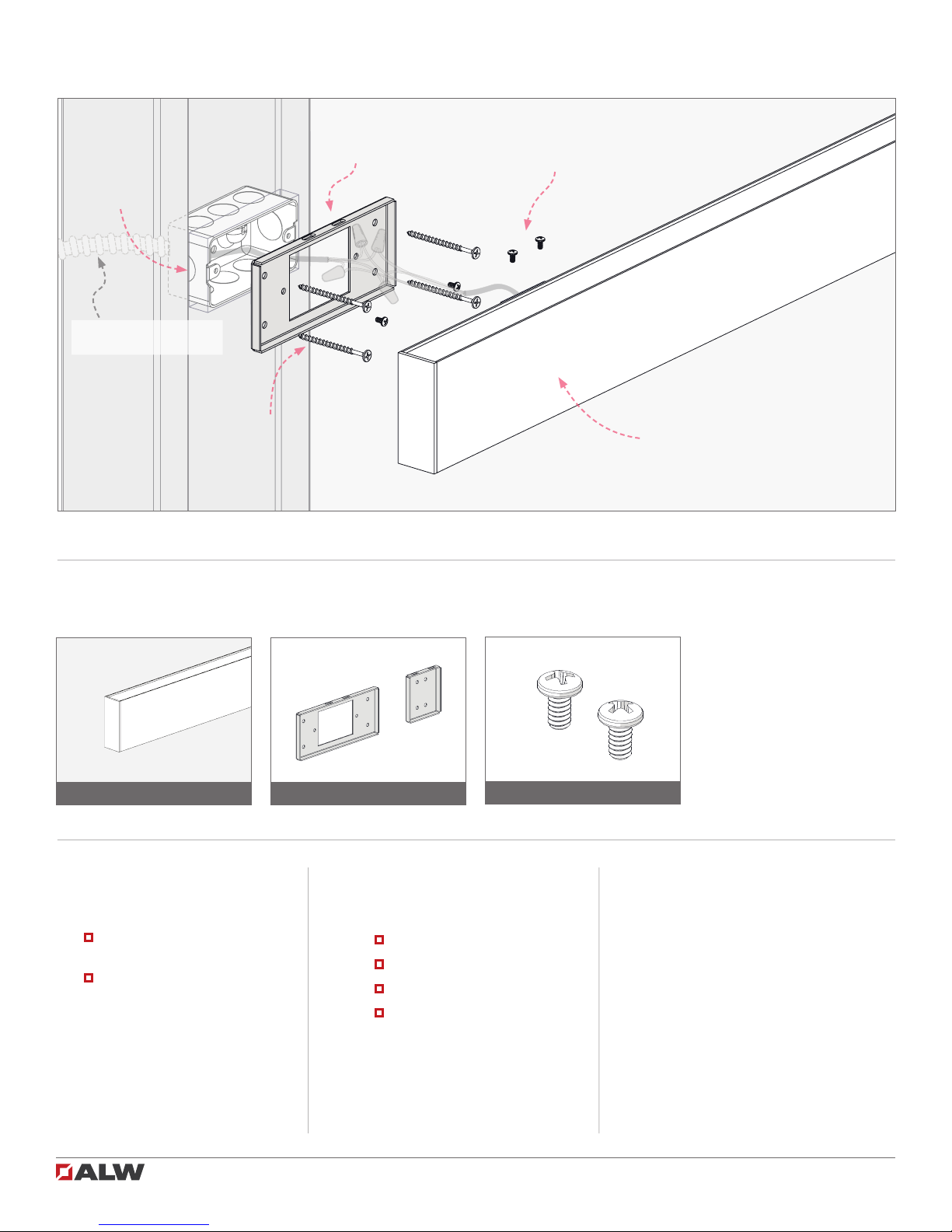
HB1.25 / MICRO Wall Mount Installation Guide 2 of 11 102-000018 - IG020519-A.0
HB1.25 / MICRO - Safety & Warnings!
1. Read all instructions.
2. Install in accordance with national and local electrical code regulations.
3. This product is intended to be installed and serviced by a qualied, licensed electrician.
4. Do not install in wet locations. For dry and damp use only.
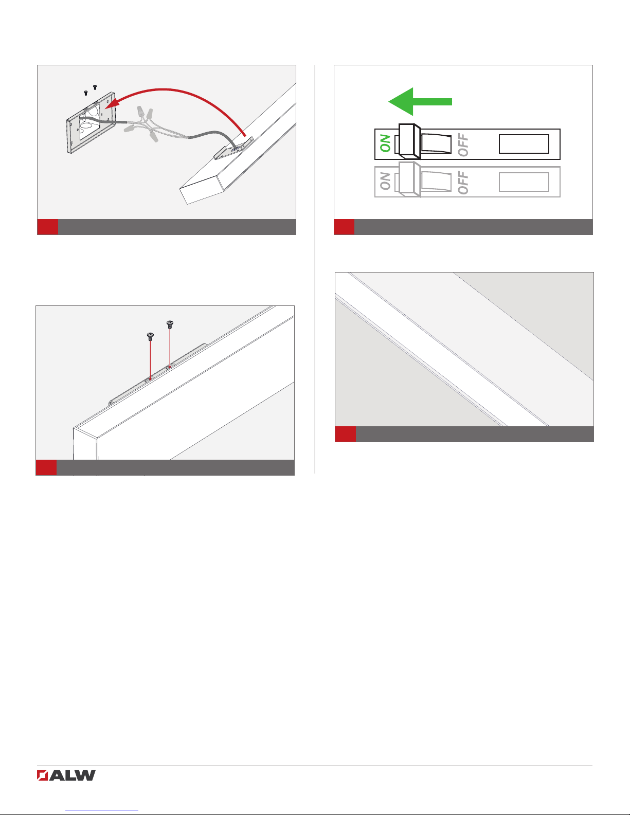
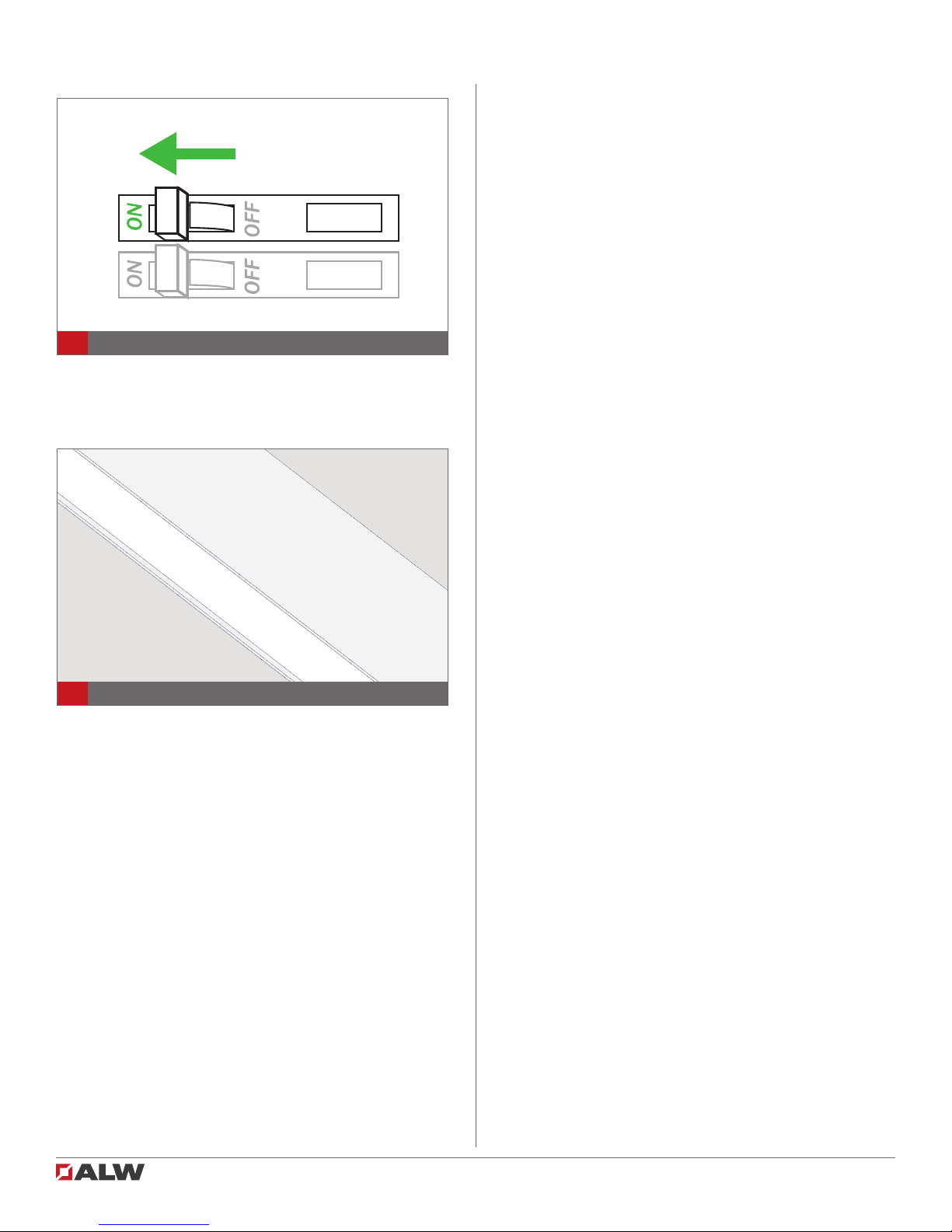
5. Turn off electrical power before installing or servicing xture in any way.
6. To reduce the risk of re and overheating, make sure all connections are tight.
7. This product is suitable for continuous row mounting.
1. Lisez toutes les instructions.
2. Installez conformément à la réglementation du code électrique national et local.
3. Ce produit est destiné à être installé et entretenu par un électricien agréé qualié.
4. Ne pas installer à l’extérieur ou dans des endroits humides. Pour une utilisation en intérieur et sec
seulement.
5. Coupez l’alimentation électrique avant de évoluer le système d’éclairage en aucune façon.
6. Pour réduire le risque d’incendie et de surchauffe, assurez-vous que toutes les connexions sont bien
serrées.
7. Peut être monté en rangée continue.
HB1.25 / MICRO - Attention!
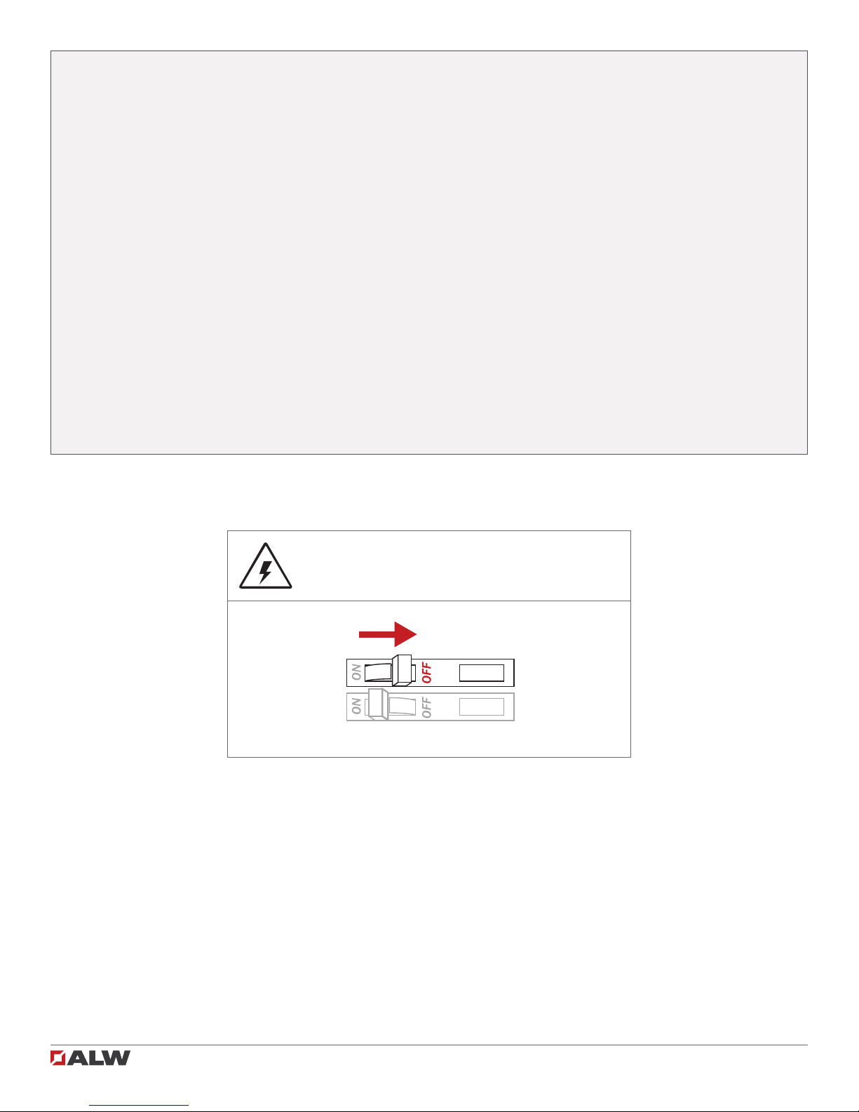
SHOCK HAZARD! May result in serious injury or
death. Turn power OFF at circuit breaker prior
to installation or servicing.