ALW LIGHTPLANE 1 User manual

A1035 22nd Avenue, Unit 1 nOakland, CA 94606 P510.489.2530 ETalkToUs@alwusa.com Walwusa.com
INSTALLATION INSTRUCTIONS
LIGHTPLANE 1
LP1 | Suspended | LED

LP1 Suspended Installation Guide 2 of 10 102-000028 - IG121818-A.0
Safety & Warnings!
1. Read all instructions.
2. Install in accordance with national and local electrical code regulations.
3. This product is intended to be installed and serviced by a qualied, licensed electrician.
4. Only install with a compatible Class 2 LED Driver. This product has not been evaluated for use when
connected to an LED driver that does not comply with Class 2 voltage and energy limited supplies.
5. Do not install in wet locations. For dry and damp use only.
6. Turn off electrical power before installing or servicing xture in any way.
7. To reduce the risk of re and overheating, make sure all connections are tight.
1. Lisez toutes les instructions.
2. Installez conformément à la réglementation du code électrique national et local.
3. Ce produit est destiné à être installé et entretenu par un électricien agréé qualié.
4. Installez uniquement avec un pilote de classe 2 compatible. Ce produit n’a pas été évalué pour une
utilisation lorsqu’il est connecté à un pilote de DEL qui n’est pas conforme aux alimentations de classe
2 à tension et énergie limitées.
5. Ne pas installer à l’extérieur ou dans des endroits humides. Pour une utilisation en intérieur et sec
seulement.
6. Coupez l’alimentation électrique avant de évoluer le système d’éclairage en aucune façon.
7. Pour réduire le risque d’incendie et de surchauffe, assurez-vous que toutes les connexions sont bien
serrées.
Attention!
SHOCK HAZARD! May result in serious injury or
death. Turn power OFF at circuit breaker prior
to installation or servicing.

LP1 Suspended Installation Guide LP1 Suspended Installation Guide 3 of 10 102-000028 - IG121818-A.0
Table of Contents
Troubleshooting 9
Wiring Diagrams 10
Installation 5
Prepare Ceiling 5
Standard Suspension 5
Connecting Multiple Sections 7
Luminaire Overview 4
Diagrams 4
Components 4
Parts (by others) 4
Tools Required 4
Quick Specs 4

LP1 Suspended Installation Guide 4 of 10 102-000028 - IG121818-A.0
LUMINAIRE OVERVIEW
Drill
#2 phillips bit
Tools Required
Wire strippers
Input Voltage / Frequency:
See product label
Rated Power:
See product drawing
Ambient Temperature:
-4° – 120°F (-20° – 50°C)
Environment:
Dry and damp locations
Quick Specs
STANDARD SUSPENSION COMPONENTS
Suspension BulletCanopy Assembly Suspension Cable Ceiling Fitting
Canopy J-Box
Ceiling Fitting /
Suspension Bullet
To Class 2 Remote Driver (not pictured)
Canopy
Plenum Cable
Suspension Cables
Cable Gripper
Fixture Body
Junction Box
Parts (by others)
Wood Screws, #10, 1.5”
long
5/64” Hex Key (for Joining)

LP1 Suspended Installation Guide 5 of 10 102-000028 - IG121818-A.0LP1 Suspended Installation Guide
Ceiling Fittings may also be mounted using toggle bolts.
4BInstall Ceiling Fitting - Toggle Bolts
Ceiling Fittings may also be mounted on 1/4”-20
Threaded Rods.
4CInstall Ceiling Fitting - 1/4”-20 Threaded Rods
Installation: Prepare Ceiling Installation: Standard Suspension
Ceiling Fittings may be installed directly into framing with
appropriate hardware.
4AInstall Ceiling Fitting - Framing
C
L
[TYPE]
ELECTRICAL WIRING:
[TYPE] .
A
T
MUST
See nal/record drawings for mounting locations. Install
framing or strut channels with consideration for alignment
of wiring and suspension mounting locations.
1See Final/Record Drawings for Mounting Locations
SAMPLE DRAWING
C
L
[TYPE]
ELECTRICAL WIRING:
[TYPE] .
A
T
MUST
Install 4” square or octagonal Canopy J-Box at power
feed location per nal/record drawing.
2Install Canopy J-Box
SAMPLE DRAWING
Install remote driver J-Box(es) in an accessible/
serviceable location. Run low voltage wire from Remote
Driver J-Box to Canopy J-Box in accordance with local/
state/federal regulations.
3Install Remote Driver J-Box

LP1 Suspended Installation Guide 6 of 10 102-000028 - IG121818-A.0
Bring wiring and canopy assembly to Canopy J-box.
Refer to page 10 and nal/record drawing to make wiring
connections. Strain relief connection. Ensure Power is OFF
prior to connecting wiring.
10 Connect Low Voltage Wiring
Route Suspension Cable through Suspension Bullet. Ball
end should sit in Suspension Bullet. Screw Suspension Bullet
to Ceiling Fitting.
5Route Suspension Cable and Attach to Ceiling
Installation: Standard Suspension
(Cont.)
6"
Use wire snips or shears to cut Suspension Cables to
desired length. Keep an extra 6 inches of cable for
adjustments.
6Cut Suspension Cables to Desired Length 9Adjust Suspension Cable Length
Adjust xture until it is level and at desired height. Depress
top of Cable Gripper to lower xture. Keep xture
supported while lowering. Cut excess cable.
Raise xture to Suspension Cables, and attach xture by
inserting Suspension Cable through Cable Grippers.
8Raise Fixture to Suspension Cables
7Connecting Multiple Sections (If Necessary)
Please see steps 13 through 21 for directions on
connecting multiple sections.
SHOCK HAZARD! May result in serious injury or death. Turn
power OFF at circuit breaker prior to installation or servicing.

LP1 Suspended Installation Guide LP1 Suspended Installation Guide 7 of 10 102-000028 - IG121818-A.0
Mount Canopy Bracket to J-Box using provided screws,
then secure Canopy over J-Box with nial. Attach bullet
(with cable) to canopy. CAUTION: Do not pinch wire
connections.
11BCombo Canopy Installation
Mount Canopy Bracket to J-Box using provided screws,
then secure Canopy over J-Box with nial. CAUTION: Do
not pinch wire connections.
11AMount Canopy Bracket to J-Box & Secure Canopy
Installation: Standard Suspension
(Cont.)
Turn breaker ON and check if xture operates as
intended and that there are no loose connections.
12 Turn Power On
Installation: Connecting Multiple
Sections
Loosen set screws on Joining Bar and extend, as shown.
14 Extend Joining Bar
Align sections and join, as shown. CAUTION: Take care not
to pinch wires.
15 Align Sections & Join
Carefully remove metal cover to expose joiner sections.
13 Remove Cover
!
DO NOT PINCH OR PUT EXCESSIVE TENSION ON WIRES while
installing canopy.
!
DO NOT PINCH OR PUT EXCESSIVE TENSION ON WIRES while
joining sections or reattaching cover.
!
DO NOT PINCH OR PUT EXCESSIVE TENSION ON WIRES while
installing canopy.

LP1 Suspended Installation Guide 8 of 10 102-000028 - IG121818-A.0
Connect wiring quick-connects between sections. Match
each color, as shown. NOTE: Color combinations may
vary.
19 Connect Wiring Between Sections
Installation: Connecting Multiple
Sections (Cont.)
Align sections and join, as shown. CAUTION: Take care not
to pinch wires.
17 Mitered Corners: Align & Join Sections
Tighten joiner screws, as shown, using a 5/64” Hex Key.
Ensure each section is properly aligned, and that there
are no gaps between sections.
18 Mitered Corners: Tighten Joiner Screws
Re-install each metal cover. CAUTION: Do not pinch wires
while reattaching!
20 Re-install Heatsink/Reector
Tighten joiner screws, as shown, using a 5/64” Hex Key.
Ensure each section is properly aligned, and that there
are no gaps between sections.
16 Tighten Joiner Screws
Install Light Leak Cover at each joined section over
unilluminated sides, as shown.
21 Install Light Leak Cover
!
DO NOT PINCH OR PUT EXCESSIVE TENSION ON WIRES while
joining sections or reattaching cover.
!
DO NOT PINCH OR PUT EXCESSIVE TENSION ON WIRES while
joining sections or reattaching cover.

LP1 Suspended Installation Guide 9 of 10 102-000028 - IG121818-A.0LP1 Suspended Installation Guide
Troubleshooting
Full Fixture does not illuminate • Ensure all wire connections are made.
• Ensure xture is wired correctly and power is on.
• Check that circuit breaker is on and not off or tripped.
• Class 2 LED driver may be defective.
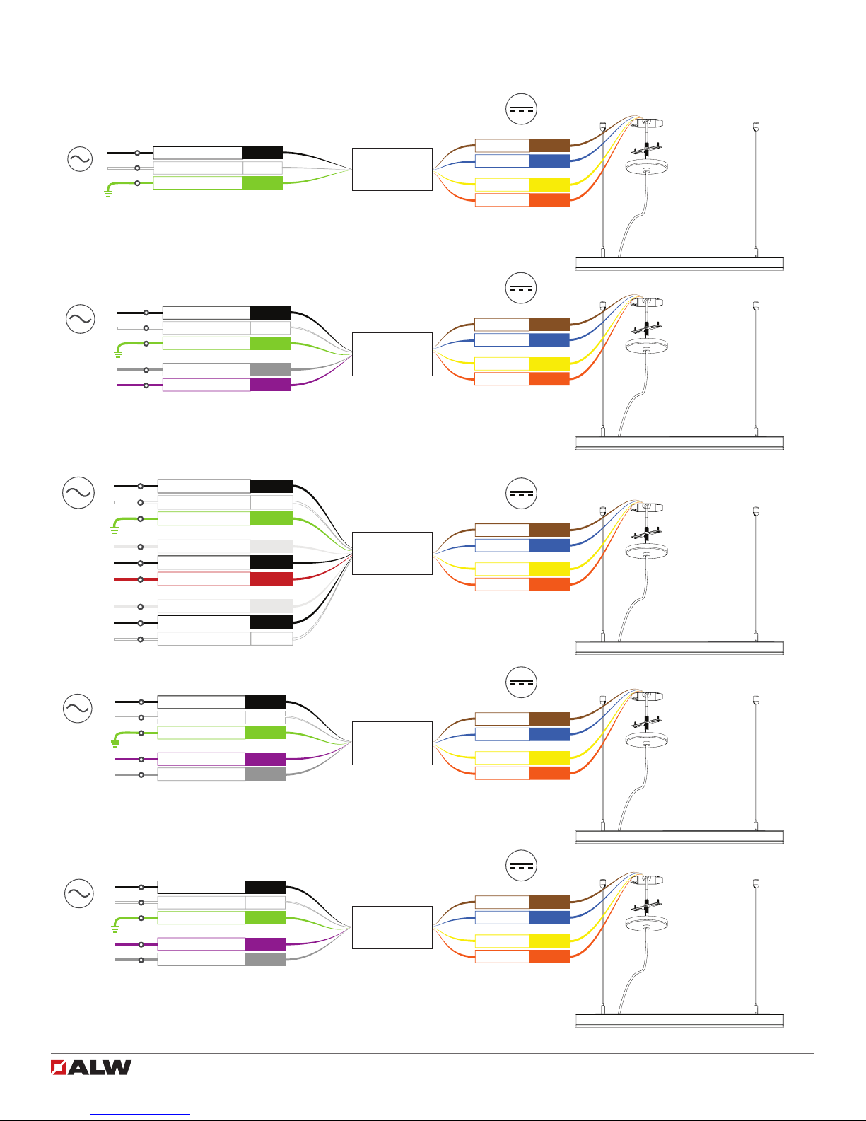
Full xture is ickering • 0-10V, DMX, and DALI Dimming Models: Ensure polarity is
correct for DATA + and - connections. Swapping DATA + and -
connections can cause ickering.
• TRIAC Dimming Models: Ensure a compatible TRIAC Forward
Phase dimmer is connected to xture. Call tech support for further
information.
• Possible loose DATA + and - connections from xture to 0-10V,
DMX, or DALI control.
• Possible loose low voltage DC + or - connection from driver to LED.
Call customer support.
Only a certied electrician can service and troubleshoot product eld issues. Always turn main power off
before servicing xture.
Fixture section(s) do not
illuminate
• Possible loose low voltage DC + or - connection between LED
boards or from LED driver to LED boards.
• Some xtures contain multiple LED drivers. In this case, it’s possible
one of the drivers is defective, which will cause the LED connected
to the driver not to illuminate. Call tech support.
Fixture section(s) are ickering • Possible loose low voltage DC + or - connection between LED
boards.
Fixture does not dim • 0-10V, DMX, and DALI Dimming Models: Ensure polarity is
correct for DATA + and - connections. Swapping DATA + and -
connections can cause ickering. TEST.
• TRIAC Dimming Models: Ensure a compatible TRIAC Forward
Phase dimmer is connected to xture. Call tech support for further
information.
• Possible loose DATA + and - connections from xture to 0-10V,
DMX, or DALI control.

LP1 Suspended Installation Guide 10 of 10 102-000028 - IG121818-A.0
Wiring Diagrams
(Colors and driver quantity may vary, consult Final/Record Drawing for more details)
Brown
Blue
Driver 1 LED +
Driver 1 LED -
Yellow
Orange
Driver 2 LED +
Driver 2 LED -
DC
Black
White
Green
Ground
Line Voltage (Hot)
Line Voltage (Neutral)
L
N
AC 50/60Hz
Traditional On/Off
Remote LED
Driver J-Box
Brown
Blue
Driver 1 LED +
Driver 1 LED -
Yellow
Orange
Driver 2 LED +
Driver 2 LED -
DC
Black
White
Green
Grey
Purple
Line Voltage (Hot)
Line Voltage (Neutral)
Ground
0-10VDC (Dim-)
0-10VDC (Dim+)
L
N
AC 50/60Hz
DIM-
DIM+
0-10V Dimming
Remote LED
Driver J-Box
Brown
Blue
Driver 1 LED +
Driver 1 LED -
Yellow
Orange
Driver 2 LED +
Driver 2 LED -
DC
Black
White
Green
Clear
Black
DMX in shield
DMX in -
Line Voltage (Hot)
Line Voltage (Neutral)
Ground
L
N
AC 50/60Hz
DMX In Shield
DMX in -
Red
DMX in +
DMX in +
Clear
Black
DMX out shield
DMX out -
White
DMX out +
DMX Out Shield
DMX out -
DMX out +
DMX
Remote LED
Driver/Decoder
J-Box
Brown
Blue
Driver 1 LED +
Driver 1 LED -
Yellow
Orange
Driver 2 LED +
Driver 2 LED -
DC
Black
White
Green
Purple
Grey
Line Voltage (Hot)
Line Voltage (Neutral)
Ground
Data +
Data -
L
N
AC 50/60Hz
DATA +
DATA -
DALI
Remote LED
Driver/Decoder
J-Box
Brown
Blue
Driver 1 LED +
Driver 1 LED -
Yellow
Orange
Driver 2 LED +
Driver 2 LED -
DC
Black
White
Green
Purple
Grey
Line Voltage (Hot)
Line Voltage (Neutral)
Ground
E1
E2
L
N
AC 50/60Hz
E1
E2
Lutron LDE
Remote LED
Driver J-Box
Canopy/Power
Feed
Canopy/Power
Feed
Canopy/Power
Feed
Canopy/Power
Feed
Canopy/Power
Feed
This manual suits for next models
1
Table of contents
Other ALW Lighting Equipment manuals
Popular Lighting Equipment manuals by other brands

walser
walser Walimex Pro Ice Sword 300 Plus instruction manual

EuroLite
EuroLite TMH-C3 user manual

NORDRIDE
NORDRIDE 4420 BEAM operating instructions

Meccanica Fadini
Meccanica Fadini MIRI 4-LED quick start guide

Luminetic
Luminetic HBT Series installation manual

PreciseLED
PreciseLED STUD 3" Linear LED installation instructions