MR-RQ Installation Guide MR-RQ Installation Guide 6 of 12 102-000031- IG071719-B.0
Align adjacent xtures
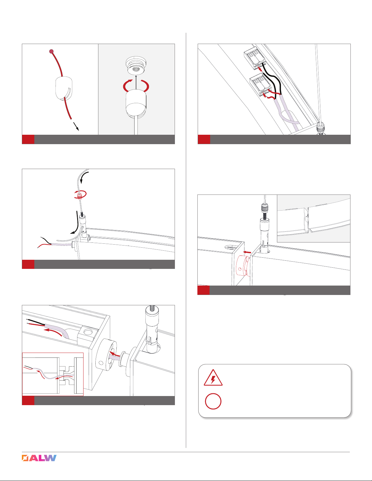
6Suspend xture
Insert other end of suspension cable through grip-
per and suspend xture at designated spot. Make
sure male joint of one section faces female joint of
other section.
Fixture sections will be labeled if required to feed
power cables from one section to another. To con-
nect power, route power cable to adjoining xture
and pass through to the indirect side. For ceiling
mount xtures, this step has to be completed before
mounting xture to ceiling.
7Feed power cable through adjoining section
9
Align male and female connectors of adjacent
xtures and pull wire into xture so that there is no
slack around rotating connectors. Lilghtly tighten set
screws with 5/64" hex key so rotating joints remain
connected but can still be adjusted. For ceiling
mount version, similary align connectors while
mounting. Make sure wires do not get pinched
between parts.
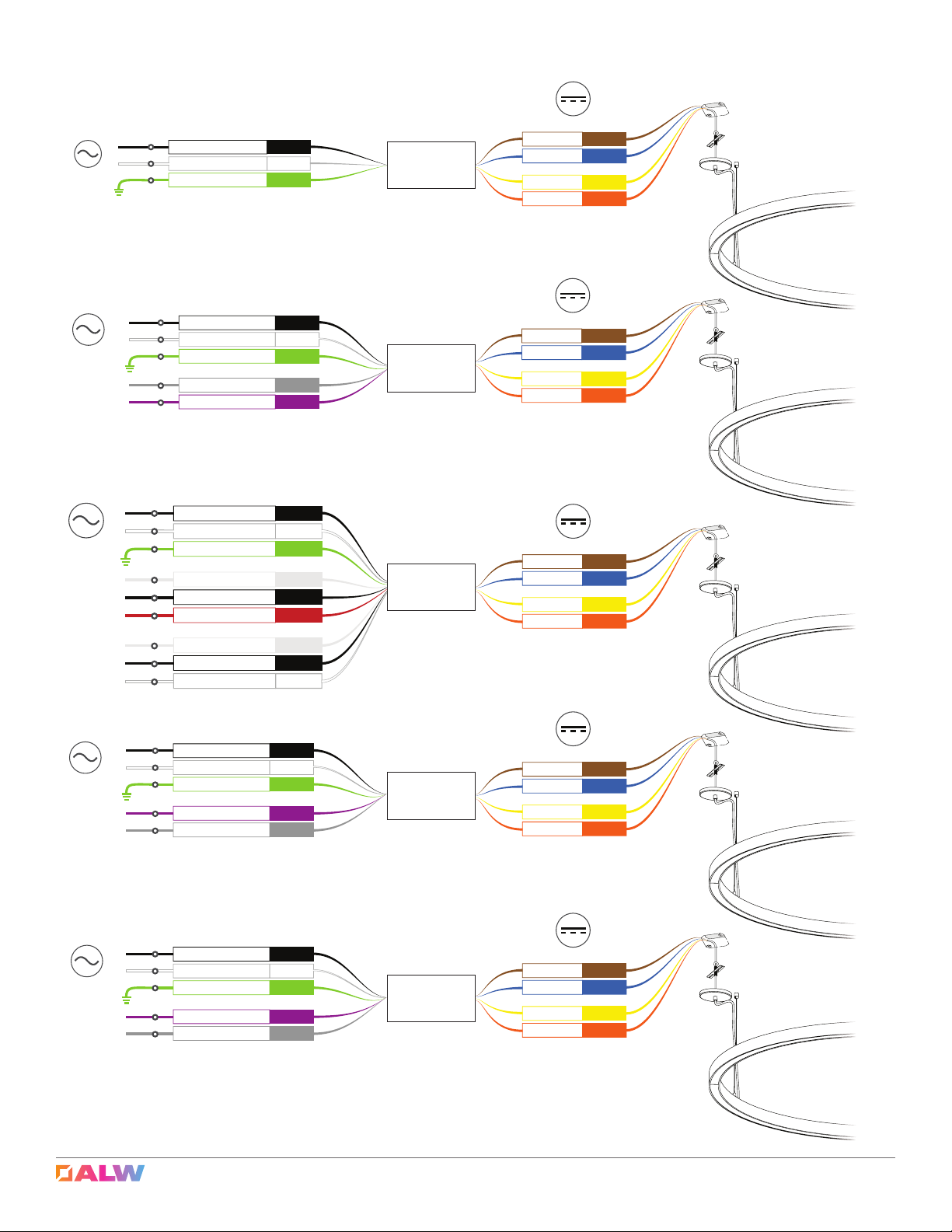
8Connect wires
Connect wires from adjacent section to lever nuts
on the indirect side. Pull lever up, insert wire and
press lever down. Make sure there are no loose
connections and polarity is correct.
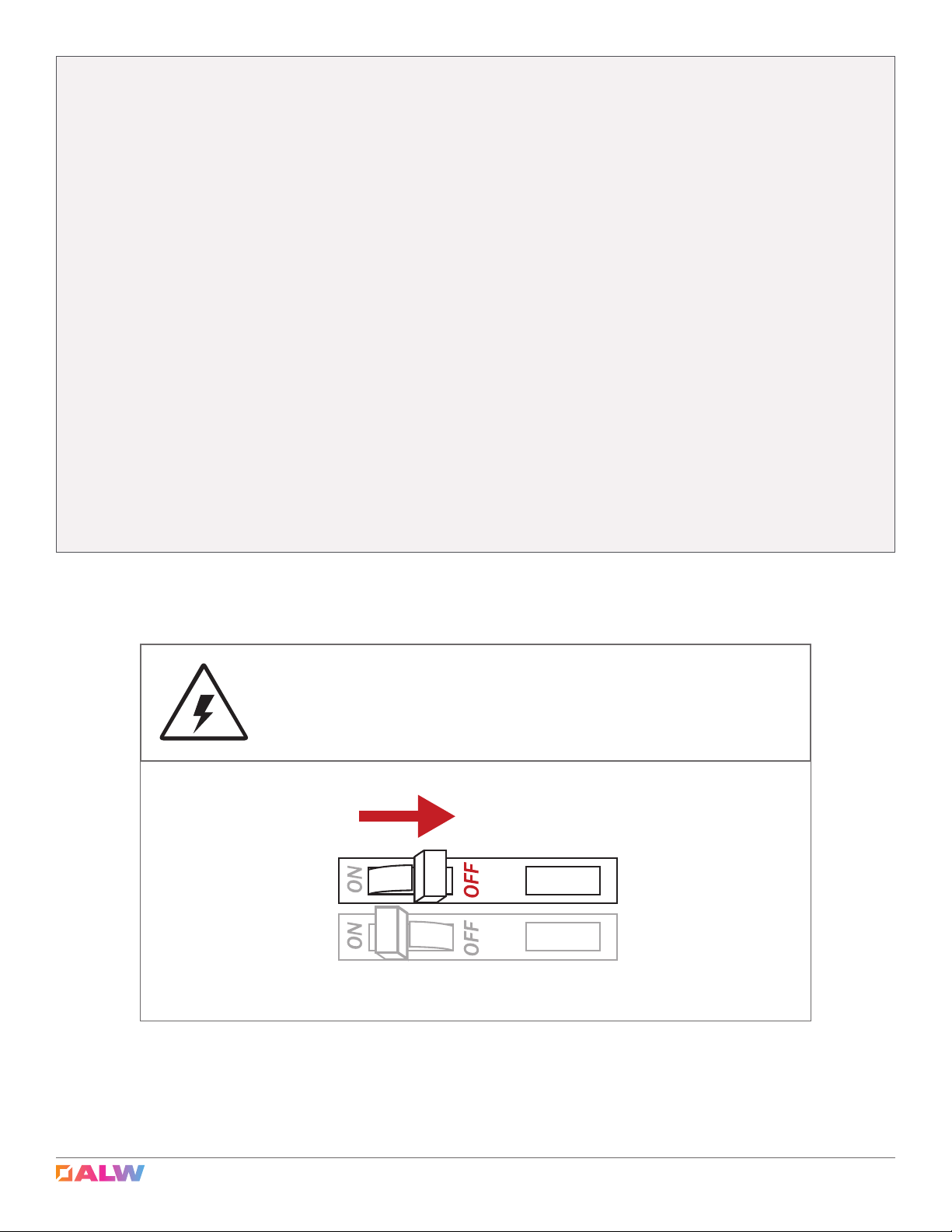
SHOCK HAZARD! May result in serious injury or
death. Turn power OFF at circuit breaker prior to
installation or servicing.
!
DO NOT PINCH OR PUT EXCESSIVE TENSION ON
WIRES while joining sections or reattaching end
caps.
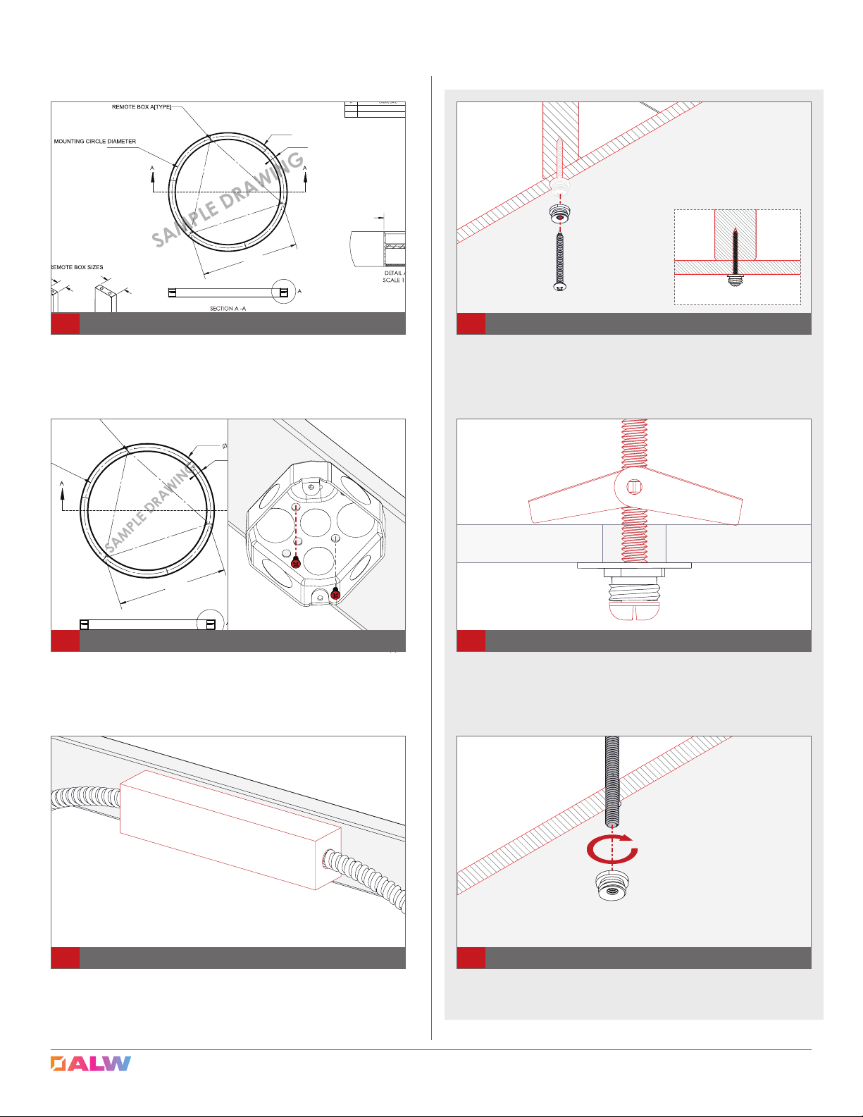
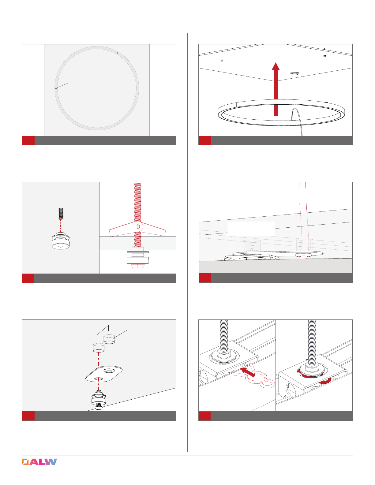
Route Suspension Cable through Suspension Bullet. Ball
end should sit in Suspension Bullet. Screw Suspension Bullet
to Ceiling Fitting.
5Route Suspension Cable and Attach to Ceiling
Installation: Fixture