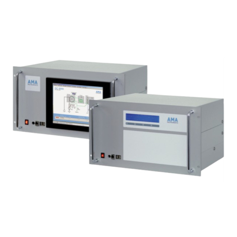
AMA Instruments GC 5000 Series User manual

OPERATING MANUAL
Gas Chromatograph – GC 5000 Series

Address of manufacturer:
AMA Instruments GmbH
Soeinger Straße 100
89077 Ulm, Germany
Tel +49 731 933-2100
Fax +49 731 933-2110
Imprint:
Operating Manual GC 5000 Series
Version 6.0; English
Date: 09/2014

Operating Manual GC 5000; Version 6 English – Date 05/2014 1
Table of Contents
Page
1.0 Information for the owner …………………………………………………........... 4
1.1 How to use the manual ……………………………………………………………… 4
1.2 Specific normal operation …………………………………………………………… 4
1.3 Delivery information …………………………………………………………………. 5
1.4 Standard and regulations …………………………………………………………… 6
1.5 Declaration of conformity …………………………………………………………… 6
1.6 Copyright ……………………………………………………………………………… 7
1.7 Service address ……………………………………………………………………… 7
2.0 Hazard Information ………………………………………………………………… 8
2.1 General hazard information ………………………………………………………… 8
2.2 Responsibility of the operator ………………………………………………………. 9
3.0 Product description - technical specifications ……………………………….. 10
3.1 Normal use of GC 5000 BTX ……………………………………………………….. 10
3.2 Normal use of GC 5000 VOC ………………………………………………………. 11
3.3 Normal use of GC 5000 Process….……………………………………………….. 12
3.4 Hardware description ……………………………………………………………….. 11
3.5 Description of GC components .…………………………….……………………… 14
3.5.1 System control and watchdog…..………………………………………………….. 14
3.5.2 GC oven ………………..…………………………………………………………….. 14
3.5.3 Columns………………………………………………………………………... ……. 14
3.5.4 Detector……………………………………………………………………………….. 14
3.5.5 Setup of parameters….……………………………………………………………… 14
3.6 Technical data - GC 5000 ……..…………………………………………………... 15
3.7 Options…………………………………………………………………………………. 17
3.7.1 Calibration gas selector (optional)………………………………………………….. 17
3.7.2 Ozone precursor monitoring system (optional) ...………………..……..………… 17
3.7.3 Optional modules (Accessories for GC 5000) ……………………………………. 18
3.7.3.1 Dilution Calibrator DIM 200 ….……………………………. ….…………..………. 18
3.7.3.2 Zero air generator ZAG 300……..…………………………. ….…………..………. 20
3.7.3.3 Hydrogen generators – HG 300 and HG 500.……………. ….…………..………. 21
4.0 Installation …………………………………………………………………………… 23
4.1 Safety instructions…………………………………………………………………… 23
4.2 Installation condition ………………………………………………………………… 24
4.3 Gas connections …………………………………………………………………….. 24
4.4 Electrical connections ………………………………………………………………. 25
5.0 Start up and shut down ..……..…………………………………………………… 26
5.1 Safety instructions …………………………………………………………………… 26
5.2 Start up instructions …………………………………………………………………. 27
5.3 Decommissioning…….. …………………………………………………………….. 29
6.0 Setting up the GC 5000 Software ……………..…………………………………. 30
6.1 Control tab…. ……………………………………..………………………..………… 30
6.2 Status tab ……………………………...………….………………………………….. 31
6.3 Events tab ………………………………………….…………………………………. 32
6.4 How to unlock – password protection ...…………………………………………… 33
6.5 Control modes ……………………………………………………………………….. 34
6.6 Communication parameters (optional) ..………………………………..…………. 34

Operating Manual GC 5000; Version 6 English – Date 05/2014 2
Page
7.0 Starting operation …..…………………………………………………………..… 37
7.1 How to start measurement…………………………………………………………. 37
7.2 How to adjust the retention time windows………………………………………… 41
7.3 How to stop measurements ………………..……………………………………… 43
8.0 Calibrating and validating ..……………………………………………………… 44
8.1 Calibration ..…………………..……………………………………………………... 44
8.1.1 Calibration intervals .……..………………………………………………….……… 44
8.1.2 Calibration setup ……………………………………………..……………….…….. 44
8.1.3 How to start a calibration…………………………….……………………………... 46
8.1.4 Check the results of the calibration ………………………………………………. 50
8.2 Validation………………………..……………………………………………………. 54
8.2.1 Principle of validation ..…..…………………………………………………………. 54
8.2.2 Types of validation ..…………………………….………………………………….. 54
8.2.3 Validation setup …………………………………….………………………………. 55
8.2.4 How to start validation .…………………………….………………………………. 57
8.2.5 Check the validation status .……………………….………………………………. 58
9.0 Time program ……………....……………………………………………………… 59
9.1 How to setup the time program .…………………………………………………... 59
9.2 How to start the time program .…………………………………………….……… 60
10.0 Functional description ..…………………………………………………………. 62
10.1 Measuring principle BTX……..…….………………………………………………. 62
10.2 Measuring principle VOC…..………………………………………………………. 63
10.3 Measuring principle Process………………………………………………………. 65
11.0 Maintenance ………………………………………………………………………... 66
11.1 Security instructions ………………………………………………………………… 66
11.2 Maintenance schedule ……………………………………………………………... 67
11.3 Maintenance work …………………………………………………………………... 68
11.3.1 Exchange the enrichment tube (BTX) ……………………………………………. 68
11.3.2 Maintenance of the pump ………………………………………………………….. 69
11.3.3 Exchange the input filter of the MFC ……………………………………………… 69
11.3.4 Exchange or repair the capillary column ………………………………............... 70
11.3.5 Adjust the detector signal ………………………………………………………….. 72
11.3.6 Adjust the ignition voltage ………………………………………………………….. 72
11.3.7 Check the glow plug ………………………………………………………………… 72
11.3.8 Check the thermocouples ………………………………………………………….. 73
11.3.9 Check the heating units of detector and valve oven ……………………………. 73
11.3.10 Exchange of the PID lamp ………………………………………………............... 74
11.3.11 Clean the PID lamp window ………………………………….……………………. 75
11.3.12 Exchange the rotor of the rotary valve …………………………………………… 75
11.3.13 Exchange the GC oven motor …………………………………………………….. 77
11.3.14 Exchange the back panel fan ……………………………………………..………. 77
11.3.15 Exchange the Peltier cooler fan (BTX) …………………………………………… 78
11.3.16 FID maintenance …………………………………………………………............... 78
11.3.17 Exchange the enrichment or focusing tube (VOC) ..……………………………. 79
11.3.18 Exchange the Peltier cooler fan (VOC) ...………………………………………… 80
12.0 Troubleshooting …………………………………………………………………… 81
12.1 General faults ……………………………………………………………………….. 81
12.2 Error messages ..……………………………………………………………………. 82
12.3 Warning messages………………………………………………………………….. 86

Operating Manual GC 5000; Version 6 English – Date 05/2014 3
Page
13.0 Spare parts list …………………………………………………………………….. 88
14.0 Warranty ……………………………………………………………………………. 89
15.0 GESYTEC-II protocol ……………………………………………………………... 90
15.1 Telegram definitions…………………………………………………………………. 90
15.2 Status request MZ…………………………………………………………………… 90
15.3 Status response ZM…………………………………………………………………. 91
15.4 Data request DA ..…………………………………………………………………… 92
15.5 Data response AD…………………………………………………………………… 92
15.6 Control command ST ………………………………………………………………. 94
15.7 Control response TS ………………………………………………………………... 94
15.8 Appendix ………..……………………………………………………………………. 95
16.0 Analog outputs …………………………………………………………………….. 96
16.1 Analog outputs connection …………………………………………………………. 96
16.2 Analog outputs configuration .……………………………………………………… 97
17.0 Digital I/O …….….………………………………………………………………….. 99
16.1 General ………………………………………………………………………………. 99
16.2 Digital outputs ………………..……………………………………………………… 100
16.3 Digital inputs …………..……..……………………………………………………… 102
18.0 Digital outputs for external calibrators……………………………………….. 103

Operating Manual GC 5000; Version 6 English – Date 05/2014 4
1 Information for the owner
1.1 How to use the manual
Caution!
Please read this manual carefully before starting with operation.
The manual will provide you with information on using, installing, operating
and maintaining this unit. It ensures proper functioning and helps you to
operate the device more easily and efficiently.
Symbols:
Caution!
Pay particular attention to all kind of warnings and notes. Information of this
type is set apart from the rest of the text and specially identified by
appropriate symbols and pictograms
1.2 Specified normal operation
Before the system left the factory, it has been inspected and found to be in
perfect condition as regards safety. To ensure a safe and problem-free
operation, the product should only be used in the manner described by the
manufacturer. In addition, proper transportation, storage and initial
installation are vital to ensure a correct and safe operation as well.
This manual provides the information you will need to use the described
product in the proper manner for which it is intended. This manual includes
several safety information (including warnings). The knowledge of this
information is essential for hazard-free installation and operation as well as
maintenance.
Therefore the manual refers to technically qualified personnel especially
trained and authorized for maintenance and service of analyzer and
monitoring devices. Moreover they possess the knowledge of correct
interpretation of the safety information and warnings provided in this
manual. This ensures as well to put it properly into practice.
Note
The GC 5000 is configured and calibrated ex factory with your required
application. In particular you intend to use the analyzer for new applications,
we recommend you to contact your local supplier to discuss the application
in question. (See chapter 2.2 and 3.1- 3.3 as well)

Operating Manual GC 5000; Version 6 English – Date 05/2014 5
1.3 Delivery information
When you receive the shipment, please check the following:
1. The packaging is not damaged.
2. Both indicators labels which are fixed on the package should display
the white color as a sign for proper transportation.
The package of the analyzer is posted with one so-called
“shockwatch” indicator label and one “tilt watch” indicator label. Both
labels change their color from white to red in case of improper
handling by the forwarder regarding tilts and shocks.
Note!
In case one of the indicator labels is red or both, note it on bill of lading,
inspect the shipment for damage and inform AMA Instruments within 10
days after arrival at latest.
The scope of delivery is corresponding to the relevant purchase contract
and is shown on the documents enclosed with the shipment:
3. Open the packaging and check whether the shipment is complete.
4. Check the serial number on the type plate with the serial number
specified in the shipping documents.
5. The operating manual is delivered on CD-ROM and recorded on the PC
of the analyzer as well.
Note!
Do not throw the original packaging away: A saver shipment is guaranteed
while using the original purpose-made packaging (it contains foamed plastic
inserts which are adapted to the size of the analyzer). Therefore we
recommend the storage of the original packaging.
6. First visual check-up of the analyzer:
When unpacking the system, remove the cover and have a closer look
to the interior of the analyzer. The following checklist may be of help:
All parts are fixed
Remove the cover of the GC oven and make a sight check of the
column
In case the column is broken, follow the instruction of chapter 13.3.4
- how to cut and repair a capillary column in the right way.

Operating Manual GC 5000; Version 6 English – Date 05/2014 6
1.4 Standards and regulations
As far as possible the specifications and manufacture of this unit are based
on the harmonized European standards.
If this product is used outside the area of validity of these standards and
regulations, the standards and regulations valid in the owner’s country
should be observed.
1.5 Declaration of conformity
Our product GC 5000
is manufactured in compliance with the following standard(s) or documents:
Low-Voltage Equipment Directive 2006/95/EG
EMC Directive 2004/108/EG
Harmonized standards EN 61326 and EN 61010
In accordance with the named above EC directives, the EC Declarations of
Conformity are kept available for the relevant Authorities by
AMA Instruments GmbH
Soeflinger Strasse 100
D-89077 Ulm / Germany
If this product is used outside the European Union, the standards and
regulations valid in the owner’s country must be observed.

Operating Manual GC 5000; Version 6 English – Date 05/2014 7
1.6 Copyright
The reproduction, transmission or use of this document or its contents is
not permitted without express written authority. Technical data are subject
to change. All rights are reserved by AMA Instruments GmbH, Ulm,
Germany.
1.7 Service address
If you require further information, which are not treated in sufficient depth in
this document or in case of malfunction, please contact your local supplier.
The responsible service engineer will provide you with the required
information.
In case of malfunction, it is recommended to have the following information
on hand:
•Detailed description of the failure
•Serial number of the system (on the back side of the analyzer)
Note!
In case of a repair, we would welcome your detailed information about the
failure in order to assure an efficient handling for a fast return shipment of
your system.
Note
For a saver shipment we recommend the use of the original packaging of
the analyzer which is purpose-made. (It contains foamed plastic inserts
which are adapted to the size of the analyzer.). For proper shipment the
system should be transported on a pallet.

Operating Manual GC 5000; Version 6 English – Date 05/2014 8
2 Hazard information
2.1 General hazard information
Please observe the following notes to safeguard against damage to the
system described as well as to any systems which may be connected to it.
Safety information and warnings are given particular emphasis in this
manual by means of various symbol terms defined below. They apply to
both, users and service / electrical technicians. They intend to help
preventing dangers to life and health as well as preventing damages to
properties. These notes are also marked by warning symbols which reflect
the meaning of the accompanying text. Within the context of this manual
and information on the product itself, the terms used are defined as follows:
Danger!
This means that death or severe injury or considerable damage to property
will result if the corresponding precautions are not taken.
Warning!
This means that death or severe injury or considerable damage to property
could occur if the corresponding precautions are not taken.
Caution!
This means that damages to property may result if the corresponding
precautions are not taken.
Note
Provides important information about the product, about using it or about a
corresponding part of the manual to which special attention has to be
shown.

Operating Manual GC 5000; Version 6 English – Date 05/2014 9
2.2 Responsibility of the operator
The analyzer described can only be used for applications which are
described in chapter 3.1. to 3.3. For operation of the systems, the technical
data described in chapter 3.4 must be observed.
The analyzer described in this manual has been designed, manufactured,
inspected and documented in compliance with the relevant safety
standards. The design of the GC 5000 BTX ensures a safe operation. If the
operator follows the handling requirements and observes safety instructions
which are described for installation, operation and maintenance, then the
system will be not a source of danger to individual health and safety or to
property.
Warning!
In case you open the unit, certain parts which apply hazardous voltage
become accessible. Only qualified and accredited technicians in the field of
electricity are permitted to have access.
Only qualified and trained personnel with a thorough knowledge of all
sources of danger are permitted to have access to this system. Regarding
the safety information in this manual, qualified personnel is defined as
follows:
•The operating personnel – They are trained in operating the system
and observing its safety requirements. As well they are familiar with the
operation-related content of this manual. This means they are able to
fully understand the English written safety instructions.
•The commissioning or maintenance personnel – They are authorized to
install, operate, maintain and repair this kind of systems and electrical
circuits in accordance with accepted technical safety standards. They
possess the authorization and appropriate training to putting into
operation, maintain and repair this system. Furthermore they are able
to fully understand the English written safety instructions and
maintenance requirements as well.

Operating Manual GC 5000; Version 6 English – Date 05/2014 10
3 Product description - technical specifications
The GC 5000 series has been developed for continuous monitoring of
organic compounds in air and gas streams. Depending on the application
requirements following models are available:
GC 5000 PROCESS
This instrument allows for monitoring of organic compounds in process and
industrial installations at ppm levels. The sample gas will be introduced
using a sample loop with well defined sampling volume.
The GC 5000 BTX
This instrument has especially been designed for ambient air monitoring
applications. The GC 5000 BTX features single-tube sample enrichment
technology and allows for monitoring of organic compounds at trace levels.
The GC 5000 VOC
This instrument has especially been designed for ambient air monitoring
applications. The GC 5000 VOC features dual-tube sample enrichment
technology and allows for monitoring of organic compounds from C
2
to C
6
at trace levels.
The following chapter describes the normal use of these three models.
3.1 Normal use of GC 5000 BTX
The AMA GC 5000 BTX suitable for the continuous monitoring of emission
and immission levels of organic compounds in ambient air and gas streams
in the range of C
4
– C
12
. The instrument is characterized by its detection
sensitivity in the low ppb to ppt range.
The analyzer is type approved according to EN 14662-3:2005 and suitable
for the legally obliged monitoring of benzene in ambient air according to the
guideline 2000/69/EC of the European parliament and the council from
November 16th 2000.
According to the EU guideline 2008/50/EC, the VDI guideline 2100 and the
guidelines of the Technical Assistance Document EPA/600-R-98/161 of the
American environmental protection agency EPA
of September 30th 1998 the analysis system is also suitable for the
continuous monitoring of ozone precursors in the range of C
4
-C
12
.
The AMA GC 5000 BTX has been developed for the continuous monitoring
General range of applications:
•Ambient air monitoring, immissions and emissions control
•Aromatic hydrocarbons (BTEX, styrene, trimethylbenzene, ethyltoluene)
•Aliphatic hydrocarbons (1,3-butadiene, methylcyclopentane,
methylhexane)
•Chlorinated hydrocarbons (vinyl chloride, trichloroethene, tetra-
chloroethene)

Operating Manual GC 5000; Version 6 English – Date 05/2014 11
The GC 5000 BTX analyzer is configured and calibrated ex factory with
your required standard application. This means that the equipment of the
system is adapted specifically to the required measuring task.
3.2 Normal use of GC 5000 VOC
The AMA GC 5000 VOC has been developed for the continuous monitoring
of emission and immission levels of organic pollutants in ambient air in the
range of C
1
– C
7
. The instrument is characterized by its compact design
and its outstanding detection sensitivity in the ppt-range.
According to the EU guideline 2002/3/EC from February 12th 2002, the VDI
guideline 2100 and the guidelines of the Technical Assistance Document
EPA/600-R-98/161 of the American environmental protection agency EPA
from September 30th 1998 the analysis system is also suitable for the
continuous monitoring of ozone precursors in the range of C
2
-C
7
(non-
aromatic).
A system for continuous monitoring of the complete range of ozone
precursor from C
2
-C
12
can be configured by combining the GC 5000 VOC
and GC 5000 BTX.
Range of applications:
•Ambient air monitoring, immissions and emissions control
•Aliphatic hydrocarbons (ethane, ethene, acetylene, propane, 1,3-
butadiene, pentane, 2-methyl-1,3-butadiene (isoprene), hexane)
•Chlorinated hydrocarbons (chloromethane, dichloromethane, vinyl
chloride, chloroethane)
The GC 5000 VOC analyzer is configured and calibrated ex factory with
your required standard application. This means the system is equipped
specifically for the required method. All necessary parameters have been
adjusted to the method.
3.3 Normal use of GC 5000 Process
The GC 5000 PROCESS has been developed for demanding applications
and operation under harsh condition in process and industrial installations.
The instrument allows for monitoring of organic compounds in air and gas
streams at ppm levels. Due to its modular design the GC 5000 Process can
be configured individually according to any specific requirement.
The temperature programmable air-bath oven is suitable for installation of
either packed or capillary columns. The temperature program with up to
three linear heating ramps allows optimization of the chromatographic
conditions in order to provide good peak separation.
Additional system modules complement the GC 5000 PROCESS providing
complete monitoring solutions. Any module features its own intelligent
Application
ex factory:
Application
ex factory:

Operating Manual GC 5000; Version 6 English – Date 05/2014 12
electronics and can be controlled by the analyzer via internal bus
communications.
For these reasons the GC 5000 PROCESS covers a wide range of
industrial and process monitoring applications.
General range of applications:
•Emissions monitoring
•Continuous monitoring of waste air in drying and distillation plants
•Monitoring of industrial processes and plants
•Aromatic hydrocarbons (BTEX, styrene, trimethylbenzene, ethyltoluene)
•Aliphatic hydrocarbons (Methane, Ethane, Ethene, Propane,
Butane,1,3- butadiene, methylcyclopentane, cyclohexane)
•Chlorinated hydrocarbons (chloromethane, vinyl chloride,
trichloroethene, tetrachloroethene)
•
Solvents (Methanol, Acetone, Methylacetate, Pyridine)
3.4 Hardware description - Overview
The GC 5000 analyzer is constructed as a 19” plug in case. All necessary
parts are integrated as there are
•electronic control unit,
•PC, monitor,
•heater controller, gas regulation etc. and
•optional equipment as output requirements, calibration gas selector or
controller for external devices as permeation modules etc.
Additionally an external monitor can be connected to the VGA interface
on the rear panel.
Fig. 1: Front view of the GC 5000 Analyzer

Operating Manual GC 5000; Version 6 English – Date 05/2014 13
Fig. 2: Rear view
Fig. 3: Gas regulation inside the analyzer

Operating Manual GC 5000; Version 6 English – Date 05/2014 14
3.5 Description of GC components
3.5.1 System control and watchdog
System control is realized via a built-in PC board with Windows 7 and the
AMA control software.
Note
The GC 5000 features a hardware watchdog. In case of a software crash
or an operating system crash, the watchdog resets the internal PC. Then
the operating system and the AMA control software are started again
automatically and the GC 5000 is operating properly again. The
automated restart of the analyzer helps your service personnel: No extra
visits to the monitoring station are necessary.
3.5.2 GC oven
The GC module features a three step temperature program. It enables to
work with high end temperatures without having long cooling down-times as
construction and used materials of the GC components are characterized
by preventing from thermal inertia.
The dimensions of the oven are 21cm * 21cm * 8cm which makes app.
3500 cm
3
. The geometry of the oven allows the use of columns with their
own cages.
The maximum linear heating rate for the range between 40 -200°C is
25°C/min, adjustable in steps of 1°C/min.
3.5.3 Columns
The dimensions of the oven allow the use of commercial capillary columns.
This helps to exchange a column in a few minutes.
The GC can be equipped with capillary columns with an internal diameter of
0.32mm, 0.45mm or 0.53 mm and up to 60m length. For standard
applications use a 0.32mm column.
3.5.4 Detector
The standard detector is a FID (Flame Ionization Detector) or a PID (Photo
Ionization Detector). The output of the detector is an analog signal of 0-5 V.
The signal is digitized and analyzed by chromatography software.
3.5.5 Setup of parameters
The control software allows to enter and to modify all analysis parameters.
Unauthorized access is avoided due to password protection.

Operating Manual GC 5000; Version 6 English – Date 05/2014 15
3.6 Technical data GC 5000
General
Case 19” plug-in case
Height 6 height units
Depth 600 mm
Weight approx. 40 kg
Ambient temperature 5°C to 35°C (if temp. exceeds this range, air conditioning is required)
Humidity 5% to 95% relative humidity, non-condensing
EMC CE-marking, conformity with EMC guideline 2004/108/EG
Instrument supply
Voltage 220-240 VAC; 110-120 VAC (optional)
Line frequency 50 to 60 Hz
Power consumption max. 800 W
Carrier gas Nitrogen GC grade (5.0 = 99.999%), 3 bar
Supply gases (for FID
only)
Combustion air, GC grade 2 bar;
H
2
, GC grade, 2 bar
Gas connections 1/8” Swagelok
Pressure control Integrated pressure regulators, electronic readout of carrier gas
pressure, manometers for indication of supply gas pressures (for
FID only)
Flow control MFC for precise flow control of hydrogen supply (for FID only)
Sampling
Sampling Maintenance-free membrane pump for automated air sampling
Volume measurement Mass flow controller with flow sensor for precise measurement and
control of sample volume irrespective of fluctuations in atmospheric
pressure and temperature (only GC 5000 BTX/VOC)
Sampling time 0-99 min (adjustable)
Flow rate MFC, 5-50 sccm/min (adjustable) (only GC 5000 BTX/VOC)
Sample volume Typical 200-800 sccm (adjustable) (only GC 5000 BTX/VOC)
MFC inlet filter Sintered metal filter, stainless steel 2µm (only GC 5000 BTX/VOC)
Sample loop 20 to 2000 µl (only GC 5000 Process)
Enrichment (only GC
5000 BTX/VOC)
Enrichment module Single-tube enrichment module with integrated thermal desorption
unit for pre-concentration of organic components ≥ C
4
Enrichment temperature Typical 30°C (adjustable)
Desorption temperature max. 350°C (adjustable)
Heating-up rate Up to 40°C/s providing high-speed sample introduction, which
results in optimized peak separation
Valve oven
Oven liner Stainless steel
Internal dimensions H 70 mm x D 80 mm x W 210 mm
Heated valve block Temperature controlled, adjustable from 40-150°C
Sample valve 6-port VALCO valve, electrically actuated

Operating Manual GC 5000; Version 6 English – Date 05/2014 16
GC oven
Oven liner Stainless steel
Internal dimensions H 55 mm x W210 mm x D 210 mm
Analytical column Fused silica capillary, length up to 60 m
Heating Forced air
Temperature range 40°C to 210 °C
Temperature control Closed loop PID, set point resolution 1°C
Temperature program 3 linear heating ramps, 4 isothermal holds
Heating rate 1°C/min to 25°C/min, set point resolution 1°C/min
Oven cooling Fast cooling down due to forced air cooling
Computer
specifications
Hardware Intel i5-3610ME 2.7GHz dual core, 4 GB RAM, 2,5” SSD
Communication ports 2x Ethernet, RS232 / RS 485, 4x USB, VGA
Display 12.1” Flat panel 1280 * 800 pixels
Protocols GESYTEC II, other protocols on request
Operating system Windows 7 Professional
Protection Password protection
Watchdog Hardware watchdog for an automated restart of the analyzer in case
of a software crash or an operating system crash.
Detector (select one
type)
FID – Flame Ionization
Detector
- Stable signal output due to temperature controlled detector block
- Make-up gas connection provides enhanced detection sensitivity
- Amplifier output 0-5 VDC
- Requires H
2
and combustion air supply
PID – Photo Ionization
Detector
- Electrode-less, radio frequency excited UC lamp provides
increased UV intensity and extended lifetime of lamp
Options for GC 5000
Touch-screen Touch controller for the flat panel
Communication Various I/O modules, analog outputs and digital I/O
Calibration Calibration gas selector (Sample, Cal1, Cal 2)
Accessories Developed for optimized connection with GC 5000
Dilution module DIM 200, Art.-No. 00002705
Zero-air generator ZAG 300 230V, Art.-No. 00002639
ZAG 300 230V incl. compressor, Art.-No. 00002794
Zero-air generator ZAG 300 110V, Art.-No. 00002692
ZAG 300 110V incl. compressor, Art.-No. 00002696
Hydrogen generator HG 300, Art.-No. 00002595
Hydrogen generator HG 500, Art.-No. 00002574

Operating Manual GC 5000; Version 6 English – Date 05/2014 17
3.7 Options
3.7.1 Calibration gas selector (optional)
The AMA GC 5000 can be equipped with two different calibration gas
supplies.
1. Calibration gas generator:
The analyzer is equipped with a communication interface to external
gas generators.
2. Calibration gas cylinders:
Fig. 4: Gas flow scheme of the calibration gas selector
Optionally the analyzer can be equipped with a valve array for the selection
of different sources of sampling. The array consists of 3 valves and can be
used for one ambient source and two calibration sources. The needle
valves of the calibration gas cylinders have to be adjusted to 70ml/min or
more.
3.7.2 Ozone precursor monitoring system (optional)
For the on-line monitoring of hydrocarbons C2-C11 (ozone precursor) in
one system, the AMA BTX analyzer can be synchronized with an AMA VOC
analyzer via Ethernet.
The software will be already configured in the factory. Then the software of
the BTX analyzer will also control the VOC analyzer. On the monitor of the
VOC analyzer you will only see a display client. The parameter setup has to
be done on the BTX analyzer.

Operating Manual GC 5000; Version 6 English – Date 05/2014 18
3.7.3 Optional Modules (Accessoiries for GC 5000)
3.7.3.1 Dilution Calibrator – DIM 200
The DIM 200 provides calibration gas at specified concentration levels for
precise calibration of monitoring devices. The calibration gas is generated
by diluting a source calibration gas with zero gas (e.g. nitrogen or purified
air).
The DIM 200 can be controlled manually or remotely via bus
communication by any AMA monitoring device or via digital I/O’s. This
allows for periodic validation and/or calibration of monitoring devices even
while running in unattended operation mode.
If the DIM 200 is controlled remotely by any AMA GC system, also setup of
the module is fully integrated into the analyzer software.
Technical data DIM 200:
General
Case 19” plug-in case
Height 3 height units
Depth 400 mm
Weight 8 kg
Mounting designed for cabinet / rack mounting
Ambient temperature 5°C to 40°C (if temp. exceeds this range, air conditioning is required)
Humidity 5% to 95% relative humidity, non-condensing
EMC CE-marking, conformity with EMC guideline 2004/108/EG
Instrument supply
Voltage 100-240 VAC
Line frequency 50 to 60 Hz
Power consumption max. 200 W
Supply gases Zero air (purified air or N
2
) 3 bar;
Source calibration gas, 3 bar
Sample gas
Supply connections 1/8” Bulkhead union for calibration gas and sample in/out
1/4” bulkhead union for zero gas and bypass
Gas flow control
Source calibration gas Mass flow controller, 2 to 100 sccm/min, accuracy +/- 0.5% of
reading
Zero gas Mass flow controller, 100 to 5000 sccm/min, accuracy +/- 0.5% of
reading
Dilution range 1 to 2500
Concentration levels Up to 5 levels (manual operation or remote control via digital I/O’s)
Up to 20 levels (remote control by AMA monitoring devices)
Gas flow concentrations Certification of the DIM 200 optionally available by factory-set
correction of flow rates determined by an independent and
accredited body for gas certification
Supplied gases Digitally controlled solenoid valves to supply either sample gas, zero
gas or calibration gas at sample out port
Microprocessor
controlled gas
calibration
Automated
calibration of
monitoring
devices
This manual suits for next models
3
Table of contents
Other AMA Instruments Laboratory Equipment manuals
Popular Laboratory Equipment manuals by other brands

SynOptics
SynOptics SYNBIOSIS ProtoCOL 3 quick guide

Fluidigm
Fluidigm Access Array user guide

CASHIDO
CASHIDO 10 Second Machine Commercial XW2 user manual

Endress+Hauser
Endress+Hauser analytikjena qTOWER3auto Series Service manual

Safelab
Safelab Airone 1000RS/E instruction manual

Steinberg Systems
Steinberg Systems SBS-LZ-3000SLS user manual