Amada MacGregor WFG-02 User manual

961-01244 rev9
Digital Force Gauge
WFG-02, WFG-07, WFG-15
OPERATION MANUAL

Operating Instructions WFG-xx
961-01244 rev9 2/14 2020-04-15
Annex:
- Safety Regulations
- General References
- Contact addresses
Versions
Version Date Basis of Version
8 2018-11 Conversion to new layout
9 2020-04 Details Update
Copyright 2020: Amada Weld Tech UK Ltd
All rights reserved.
The products named in this manual are only used for identification purposes and may be trademarks
or registered trademarks of the respective companies.

Operating Instructions WFG-xx
Table of Contents
961-01244 rev9 3/14
Table of Contents
1 General Information ...........................................................................................................4
2 Technical Description ........................................................................................................5
2.1 Technical Specification .....................................................................................................5
2.2 Introduction ........................................................................................................................6
3 Quick Start Guide ...............................................................................................................7
4 Storage ................................................................................................................................7
5 Wiring Information .............................................................................................................8
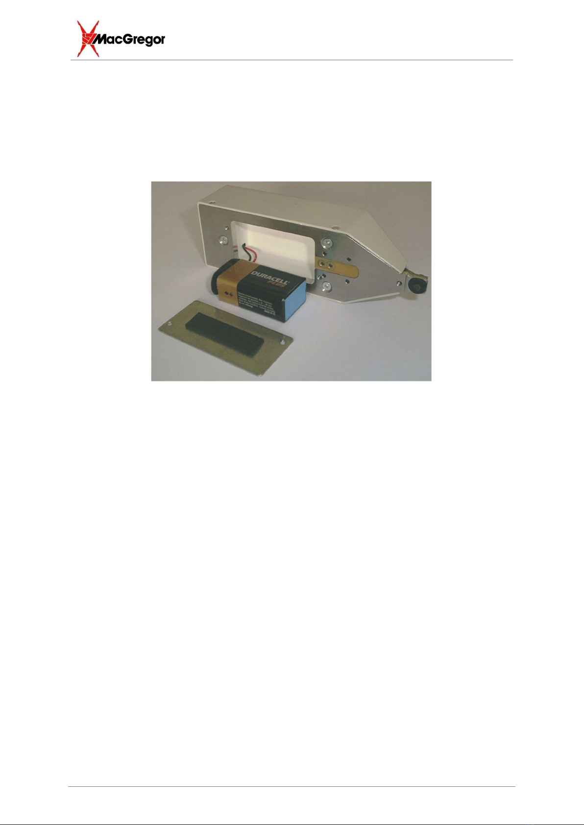
6 Battery Replacement .........................................................................................................9
7 Handling ..............................................................................................................................9
8 Manual Tare ........................................................................................................................9
9 System Description ........................................................................................................ 10
9.1 4 Digit LCD Display ......................................................................................................... 10
9.2 UNITS LED’s (Red) .......................................................................................................... 10
9.3 HOLD LED (Red).............................................................................................................. 10
9.4 FUNCTION BUTTONS ..................................................................................................... 10
9.4.1 UNITS ............................................................................................................................... 10
9.4.2 SET (POWER ON) ............................................................................................................ 10
9.4.2.1 To View Limits ................................................................................................................... 11
9.4.2.2 To Chamge the Set Point .................................................................................................. 11
9.4.2.3 To Change the Percentage ............................................................................................... 11
9.4.2.4 To Toggle Peak Hold Mode .............................................................................................. 11
9.4.3 HOLD ................................................................................................................................ 11
10 RS232 Data Link (Optional) ............................................................................................ 12
11 Analogue Output (Optional) ........................................................................................... 13
12 Index ................................................................................................................................. 14
12.1 Headword Index .............................................................................................................. 14

Operating Instructions WFG-xx
Table of Contents
961-01244 rev9 4/14
1 General Information
Information about safety regulations, symbols, copyrights, protection rights,
usage location conditions can be found in the back section of these operating
instructions.
Please read this information carefully before using these operating instructions.
These operating instructions should help you familiarize yourself with the system and
take advantage of its application possibilities when used as directed.
It contains important notes to help operate the unit safely, properly, and economically.
Observing the notes will help avoid risks, decrease repair costs and down times, and
enhance reliability and the service life of the unit.
It is a rule: Safety first!
Warning
Incorrect or inappropriate configuration, installation, settings, handling or use can cause
mechanical, electrical or thermal hazards, which may result in serious damage or injury.
Ensure the correct execution of these points and follow the respective notes in the
operating instructions.
Danger
Do not put the system into operation before you have read the operating instructions!
Danger Persons with cardiac pacemakers and metallic implants are prohibited from
approaching to within a radius of at least 5 m of welding equipment!
Crushing Hazard
There is a risk of crushing during the adjustment movement due to closing electrodes,
stops for limiting adjustment or stroke movement and the stop on the basic pincers unit
for limiting floating movement.
Warning
This Class A welding equipment is not supposed to be used in living quarters, where
the power supply is carried out by a public low voltage supply.
There it can be difficult to ensure electromagnetic compatibility because of conducted or
radiated disturbances.
Warning
Restrictions on use environment conditions
Use this equipment in an environment without conductive dust. If conductive dust
enters into equipment, it may cause failure, electric shock or ignition. If using
equipment in such environment, consult Amada Weld Tech.
Warning

Operating Instructions WFG-xx
961-01244 rev9 5/14
2 Technical Description
2.1 Technical Specification
WFG-02-x-x
WFG-07-x-x
WFG-15-x-x
Force Range Newtons
0.025 - 20 0.1 - 70 1 - 150
Force Range Pounds 0.05 – 4.5 0.22 – 15.4 0.50 – 33.7
Force Range Grams 25 -2000 100 - 7000 200 - 15000
Resolution Better than 0.2%
Accuracy Within +/-1% of FSD
at 25oC
Trigger input Contact closure (less than 10 ohms) OR voltage
input (5 to 24v)
Maximum Electrode
Diameter
6mm
Dimensions Depth
Width
Height
45mm
140mm
33mm
Weight 0.4Kg
Battery life and type 9V DC – PP3 Battery
Auto power off – Battery life > 1 year

Operating Instructions WFG-xx
961-01244 rev9 6/14
2.2 Introduction
Thank you for purchasing this MacGregor Weldhead Force Gauge.
This manual is designed to help the new user to understand and operate the equipment
quickly and safely. Please take a few moments to become familiar with the equipment
and this manual before attempting to use the equipment.
The following information covers the model you have purchased and others in the range
and should be kept for reference. This will also help you identify model specific features
mentioned in this manual.
The Weldhead Force Gauge (WFG) has the following features :-
* Precision Thin Film Strain Gauge sensing element for precise and temperature
stable measurement of welding force.
* Data HOLD function by front panel button or remote trigger.
* Peak hold mode for capturing increased transient forces after weld trigger points.
* User selectable units, options are Pounds, Grammes or Newtons.
* Automatic and manual tare function.
* Operator mode, using set point and upper/lower percentage limits.
* Optional data transfer of the weld force to PC application, including error codes,
units, limits, etc.
*
Can be linked to the MacGregor range of weld heads, so force is measured at the
point the weld is triggered. Can be linked to other heads or systems.
* Unit calibration carried out via the serial port (Return to Amada Weld Tech).
* Audible indication of errors, including overload, high/low force.

Operating Instructions WFG-xx
961-01244 rev9 7/14
3 Quick Start Guide
1) Without applying any load to the sensing element, press the SET button to switch
the unit ‘on’.
2) The display will flash ‘8888’ then confirm the model (20N on the WFG2, 70N on
the WFG7 or 150N on the WFG15), and all the LED’s will light up. During this
time, no load should be applied to the unit, as the unit is carrying out an auto tare.
Once the display clears, then the unit is ready to operate. If on the WFG2 a load
above 15grams is applied, (or 50grams for the WFG7, or 100grams for the
WFG15,) during power on, then the unit will display ‘Err’ and switch off.
3) Carefully place the sensing element between the electrodes of the weldhead.
Lower the weldhead onto the gauge. The display shows the force being applied.
4) If the unit is being used with a MacGregor Weldhead, then the supplied trigger
cable may be used to obtain an accurate reading of the welding force. The action
of the microswitch closing in the weldhead causes the reading on the display to
be held.
5) The units may be changed by repeatedly pressing the units button until the
appropriate ones are displayed.
4 Storage
Once the gauge has been used, it is important that it is placed in a safe place to avoid damage.
If the unit is to be stored for extended periods of time, it is recommended that the battery is removed.
So as to avoid thermal stock and condensation, make sure environmental conditions for storage and
use are similar. Avoid chemicals and dusty environments.

Operating Instructions WFG-xx
961-01244 rev9 8/14
5 Wiring Information
All connections are made to the digital force gauge through the RJ45 and jack socket on the rear of
the unit.
RJ45 socket: This is the communications and calibration port. The supplied cable (part
number 602-22324) can be used to log force data to a PC, running the optional application
software FORCE-PC.
⅛” Jack Socket: Remote trigger input. The supplied cable (part number 602-22323) can be
used to trigger the HOLD feature from a MacGregor weld head.
Inserting the plug triggers a ‘HOLD’.
Alternatively, the unit may be triggered by another manufacturers weldhead/system, please
follow the connection diagram shown below.
If using a contact closure, then connect the switch between the ‘+5V’ and ‘switch’.
If using a voltage input, connect the system 0v to ‘0v’. Connect the voltage input to
‘switch’. (voltage range +5 to +24v).
Warning :- Do not insert a mono jack plug, as this will cause damage to the system.
0v
switch
+5V

Operating Instructions WFG-xx
961-01244 rev9 9/14
6 Battery Replacement
The unit is provided fitted with a PP3 (9V) battery. Battery replacement is carried out by removing the
cover on the base of the unit. A low battery is indicated by ‘Bat’ flashing on the display. Failure to
change the battery when this is indicated may result in incorrect readings being recorded. For long life,
we recommend the use of a lithium manganese battery.
7 Handling
The MacGregor Digital Force Gauge is a precision instrument and should be treated as such.
Overloading, dropping, shocks, etc will cause damage to the unit. It is important that the gauge is
moved using the body of the gauge, and NOT by the sensing element. Failure to do so may cause
damage to the gauge.
Before use, check that no debris has accumulated underneath the beam, and in particular between
the beam and the overload protection screw.
8 Manual Tare
When the unit powers on, various self tests are carried out, including an automatic tare. This will
operate for loads up to 15 grams WFG2 (50grams for the WFG7, or 100grams for the WFG15), any
more and the unit displays ‘Err’, sounds an alarm and then switches off.
Once the unit is on, at any time a manual tare can be carried out as follows.
1) Press the ‘HOLD’ button.
2) Within 2 seconds of pressing ‘HOLD’, press the ‘UNITS’ button.
3) Maintain the ‘UNITS’ button down until the display shows all zeros, and release.
4) Whatever load was applied on the gauge when the ‘UNITS’ button was pressed and all zeros
appear is now tared to zero.

Operating Instructions WFG-xx
961-01244 rev9 10/14
9 System Description
9.1 4 Digit LCD Display
The welding force reading is displayed on a 4-digit LCD. The force reading is displayed in real time
until the HOLD or remote trigger input are energized.
The unit will indicate a high (HI) or low (LO) limit fault and sound an audible warning if the force is out
of range when the trigger is energized or HOLD button activated.
Important
The maximum range of the WFG2 gauge is 2.0Kg (7Kg for WFG7 and15Kg for WFG15). If the gauge
experiences a load greater than this, then the display indicates OL (OverLoad), and an audible
indication is given. The excessive force should be removed immediately, to avoid damage to the
loadcell. This invalidates the warranty; the number of overloads is recorded within the device.
9.2 UNITS LED’s (Red)
Located on the left hand side of the unit are three LED’s labeled lbs, g (Kg on the WFG15), and N.
These provide an indication of the units, pounds, grammes or Newtons.
9.3 HOLD LED (Red)
There is a red HOLD LED located on the left hand side of the unit. This LED is lit when the display is
frozen due to the HOLD button or remote trigger input being energized. It will also illuminate when the
unit is in SET mode.
9.4 FUNCTION BUTTONS
There are three function buttons located on the gauge. These operate as follows.
9.4.1 UNITS
The units button allows the user to switch the displayed force units. The system can display Grams
(G) on the WFG2/WFG7 (or Kilo Grams (Kg) on the WFG15) , Newtons (N), and Pounds (Lbs). The
values for the measured force and the limits are automatically converted allowing the displayed units
to be changed without altering the programmed set point.
To change the units on the display, press the UNITS button, ‘UNIT’ appears on the screen. To toggle
the UNIT setting, press the UNITS button again until the desired LED is illuminated. After several
seconds the screen will display the current force reading in the selected unit value and the appropriate
LED will remain lit.
9.4.2 SET (POWER ON)
Pressing this button turns on the unit. The set button allows the force limits and settings to be viewed
or input into the unit. The set button also is involved in toggling peak hold mode.

Operating Instructions WFG-xx
961-01244 rev9 11/14
9.4.2.1 To View Limits
Press the SET button once. The red HOLD LED illuminates. The unit will automatically display the set
point, and then after a short delay the percentage tolerance. The display then clears back to the
normal display, and the red HOLD LED turns off.
9.4.2.2 To Chamge the Set Point
Press the SET button so the set force is displayed (HOLD LED illuminates). While this is displayed,
press the UNITS button. The screen will now alternate between NO and the indicated force value.
Apply the required load onto the sensing element and then press SET, or apply a trigger to the rear
socket. The display now shows the previously selected limits and then clears back to the normal
display, and the red HOLD LED turns off.
9.4.2.3 To Change the Percentage
Press the SET button once. The red HOLD LED illuminates. The unit will automatically display the set
point, and then after a short delay the percentage tolerance. While the tolerance is displayed, press
the UNITS button. The options are OFF (no limit checking), +/-2.5%, +/-5%, +/-10% or +/-20% of
nominal value. Once the desired limits are selected, press the SET button to confirm. The Red HOLD
LED will turn off and the unit will return to the normal display.
9.4.2.4 To Toggle Peak Hold Mode
Press the SET button once and then press the HOLD button. Upon releasing the hold button the
display will periodically flash “PH” to indicate that the unit is in peak hold mode. Pressing the HOLD
button in this mode will clear the peak value back to zero. In this mode, pressing the HOLD button will
not trigger a logging event over the RS232 channel as it does in the normal mode. Press the SET
button once and then press the HOLD button to return to the normal operating mode.
9.4.3 HOLD
The HOLD button allows the current reading on the display to be held (data is automatically
transmitted on the communications port). The reading is maintained for 10 seconds. The hold may be
cancelled by pressing HOLD again. If the limits have been turned on, then the unit will only hold the
value if it is in range, otherwise HI or LO are displayed and an audible warning sounded.

Operating Instructions WFG-xx
961-01244 rev9 12/14
10 RS232 Data Link (Optional)
On the rear of the gauge is a 6 way RJ45 connector for the RS232 link. Please refer to the FORCE PC
manual for instructions regarding use and installation of the PC data capture tools.
Each time the HOLD button is pressed or the trigger input is energized, then the force data is
transmitted out of the RS232 port.
This port is also used for calibration of the system. Please contact a Amada Weld Tech office for
information regarding calibration.

Operating Instructions WFG-xx
961-01244 rev9 13/14
11 Analogue Output (Optional)
In addition to the features described in this manual, this 20N/70N/150N handheld force gauge has
analog signals brought out to a connector on the back panel, in addition to the connectors normally to
be found there.
The signals are a voltage from the sensor signal conditioning subsystem which represents the force
on the load cell; the other signal is a ground reference. The voltage should be approximately 0.5V at
no-load and 4.5V at full load (2Kg/7kg/15kg) with respect to the ground reference.
The signal is an output from an opamp and is NOT protected or buffered. Coupling noise to the ground
reference or the signal itself will degrade the performance of the force gauge. Drawing excessive
current from the signal line will also degrade and possibly permanently damage the force gauge. To
avoid damage and to minimise degradation of the performance of the force gauge, restrict the current
drawn from the signal line to no more than 1mA. The 2.5mm plug may transiently short the signal to
ground during insertion or removal. Ensure that the unit is powered down before attempting the
insertion or removal of this plug. The signals are NOT isolated from any of the other signals available
at the back panel so extra care should be taken when connecting this device to a system in a welding
environment.
The signal is filtered internally to reduce high frequency noise. The signal is brought out to the back
panel prior to any filtering. It is recommended that the signal be filtered with an RC filter externally e.g.
a 10k resistor and a 1uF capacitor.

Operating Instructions WFG-xx
961-01244 rev9 14/14
12 Index
12.1 Headword Index
4
4 Digit LCD Display ........................................................................ 11
A
Analogue Output (Optional) ........................................................... 14
B
Battery Replacement...................................................................... 10
F
FUNCTION BUTTONS .................................................................. 11
G
General Information ......................................................................... 5
H
Handling ......................................................................................... 10
HOLD ............................................................................................. 12
HOLD LED (Red) ........................................................................... 11
I
Introduction....................................................................................... 7
M
Manual Tare ................................................................................... 10
Q
Quick Start Guide ............................................................................ 8
R
RS232 Data Link (Optional) ........................................................... 13
S
SET (POWER ON) ........................................................................ 11
Storage ............................................................................................ 8
System Description ........................................................................ 11
T
Technical Description ...................................................................... 6
Technical Specification .................................................................... 6
To Change the Percentage ........................................................... 12
To Change the Set Point ............................................................... 12
To Toggle Peak Hold Mode ........................................................... 12
To View Limits ............................................................................... 12
U
UNITS ............................................................................................ 11
UNITS LED’s (Red) ....................................................................... 11
W
Wiring Information ............................................................................ 9
This manual suits for next models
2
Table of contents