Burkert 8177 User manual

Operating Instructions
LEVEL TRANSMITTER
8177
4…20 mA/HART

Contents
1About this document
1.1Function. . . . . . . . . . . . . . . . . . . . . . . . . . . . . . . . . . 4
1.2Target group . . . . . . . . . . . . . . . . . . . . . . . . . . . . . . 4
1.3Symbolism used. . . . . . . . . . . . . . . . . . . . . . . . . . . . 4
2For your safety
2.1Authorised personnel . . . . . . . . . . . . . . . . . . . . . . . . 5
2.2Appropriate use . . . . . . . . . . . . . . . . . . . . . . . . . . . . 5
2.3Warning about misuse . . . . . . . . . . . . . . . . . . . . . . . 5
2.4General safety instructions . . . . . . . . . . . . . . . . . . . . 5
2.5Safety approval markings and safety tips . . . . . . . . . . 6
2.6CE conformity . . . . . . . . . . . . . . . . . . . . . . . . . . . . . 6
2.7Compatibility according to NAMUR NE 53 . . . . . . . . . 6
2.8Safety instructions for Ex areas . . . . . . . . . . . . . . . . . 6
3Product description
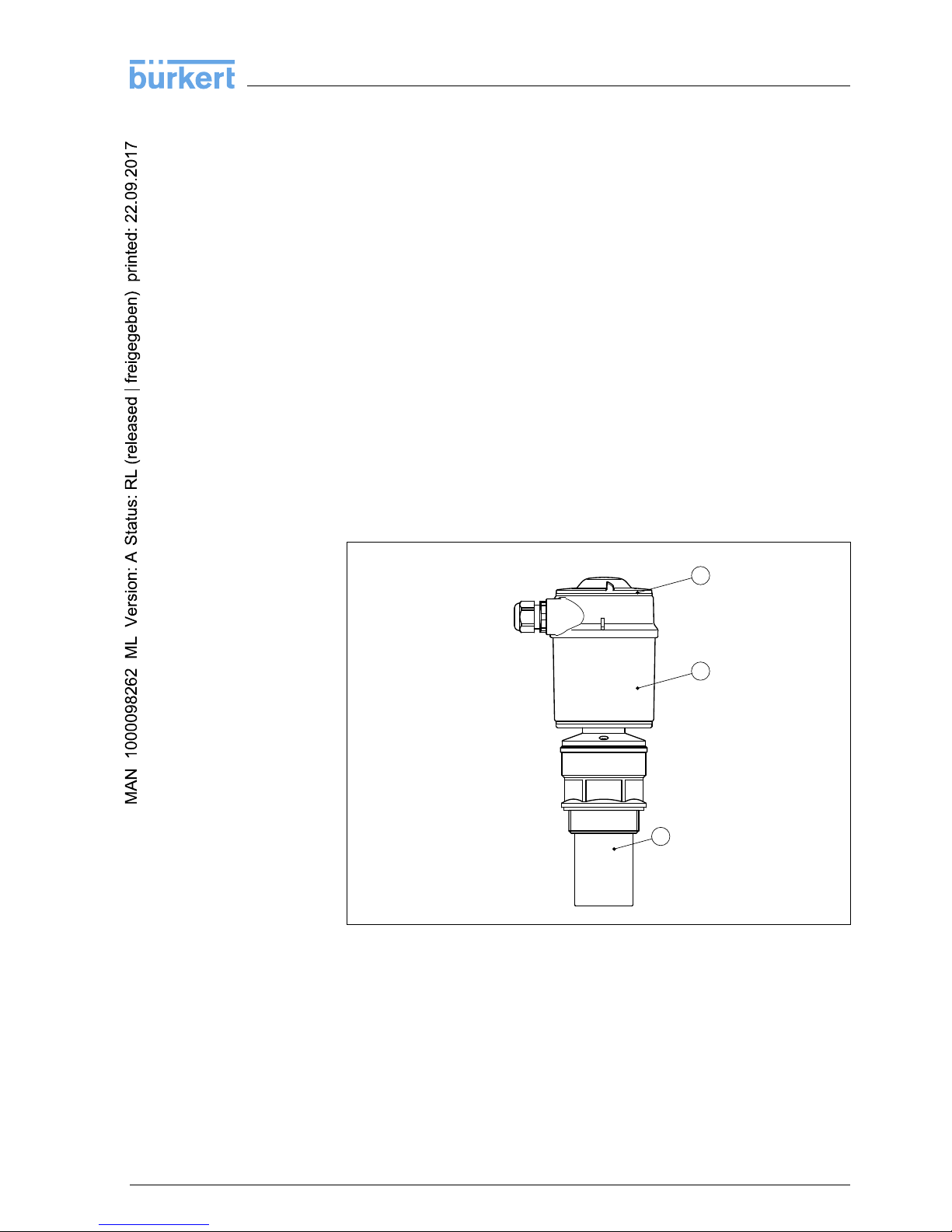
3.1Configuration . . . . . . . . . . . . . . . . . . . . . . . . . . . . . . 7
3.2Principle of operation . . . . . . . . . . . . . . . . . . . . . . . . 7
3.3Operation. . . . . . . . . . . . . . . . . . . . . . . . . . . . . . . . . 8
3.4Packaging,transport and storage . . . . . . . . . . . . . . . 8
4Mounting
4.1General instructions . . . . . . . . . . . . . . . . . . . . . . . . . 10
4.2Mounting instructions . . . . . . . . . . . . . . . . . . . . . . . . 12
5Connecting to power supply
5.1Preparing the connection . . . . . . . . . . . . . . . . . . . . . 18
5.2Connection procedure. . . . . . . . . . . . . . . . . . . . . . . . 19
5.3Wiring plan,single chamber housing . . . . . . . . . . . . . 20
5.4Switch on phase. . . . . . . . . . . . . . . . . . . . . . . . . . . . 21
6Set up with the indicating and adjustment module
6.1Short description . . . . . . . . . . . . . . . . . . . . . . . . . . . 22
6.2Insert indicating and adjustment module. . . . . . . . . . . 22
6.3Adjustment system . . . . . . . . . . . . . . . . . . . . . . . . . . 24
6.4Setup procedure. . . . . . . . . . . . . . . . . . . . . . . . . . . . 25
6.5Menu plan ultrasonic sensor . . . . . . . . . . . . . . . . . . . 31
6.6Saving the parameter adjustment data. . . . . . . . . . . . 33
7Maintenance and fault rectification
7.1Maintenance . . . . . . . . . . . . . . . . . . . . . . . . . . . . . . 34
7.2Remove interferences. . . . . . . . . . . . . . . . . . . . . . . . 34
8Dismounting
8.1Dismounting steps . . . . . . . . . . . . . . . . . . . . . . . . . . 36
8.2Disposal . . . . . . . . . . . . . . . . . . . . . . . . . . . . . . . . . 36
2LEVEL TRANSMITTER 8177 •4…20 mA/HART
Contents
32059-EN-081121

9Supplement
9.1Technical data . . . . . . . . . . . . . . . . . . . . . . . . . . . . . 37
9.2Dimensions . . . . . . . . . . . . . . . . . . . . . . . . . . . . . . . 41
Supplementary documentation
Information:
Supplementary documents appropriate to the ordered version come
with the delivery.You can find them listed in chapter "Product
description".
LEVEL TRANSMITTER 8177 •4…20 mA/HART 3
Contents
32059-EN-081121

1About this document
1.1Function
This operating instructions manual provides all the information you
need for mounting,connection and setup as well as important
instructions for maintenance and fault rectification.Please read this
information before putting the instrument into operation and keep this
manual accessible in the immediate vicinity of the device.
1.2Target group
This operating instructions manual is directed to trained qualified
personnel.The contents of this manual should be made available to
these personnel and put into practice by them.
1.3Symbolism used
Information,tip,note
This symbol indicates helpful additional information.
Caution:If this warning is ignored,faults or malfunctions can
result.
Warning:If this warning is ignored,injury to persons and/or serious
damage to the instrument can result.
Danger:If this warning is ignored,serious injury to persons and/or
destruction of the instrument can result.
Ex applications
This symbol indicates special instructions for Ex applications.
lList
The dot set in front indicates a list with no implied sequence.
àAction
This arrow indicates a single action.
1Sequence
Numbers set in front indicate successive steps in a procedure.
4LEVEL TRANSMITTER 8177 •4…20 mA/HART
1About this document
32059-EN-081121

2For your safety
2.1Authorised personnel
All operations described in this operating instructions manual must be
carried out only by trained specialist personnel authorised by the plant
operator.
During work on and with the device the required personal protective
equipment must always be worn.
2.2Appropriate use
LEVEL TRANSMITTER 8177 is a sensor for continuous level
measurement.
You can find detailed information on the application range in chapter
"Product description".
Operational reliability is ensured only if the instrument is properly used
according to the specifications in the operating instructions manual as
well as possible supplementary instructions.
For safety and warranty reasons,any invasive work on the device
beyond that described in the operating instructions manual may be
carried out only by personnel authorised by the manufacturer.Arbitrary
conversions or modifications are explicitly forbidden.
2.3Warning about misuse
Inappropriate or incorrect use of the instrument can give rise to
application-specific hazards,e.g.vessel overfill or damage to system
components through incorrect mounting or adjustment.
2.4General safety instructions
This is a high-tech instrument requiring the strict observance of
standard regulations and guidelines.The user must take note of the
safety instructions in this operating instructions manual,the country-
specific installation standards as well as all prevailing safety
regulations and accident prevention rules.
The instrument must only be operated in a technically flawless and
reliable condition.The operator is responsible for trouble-free
operation of the instrument.
During the entire duration of use,the user is obliged to determine the
compliance of the required occupational safety measures with the
current valid rules and regulations and also take note of new
regulations.
LEVEL TRANSMITTER 8177 •4…20 mA/HART 5
2For your safety
32059-EN-081121

2.5Safety approval markings and safety tips
The safety approval markings and safety tips on the device must be
observed.
2.6CE conformity
The instrument is in CE conformity with EMC (89/336/EWG), fulfils
NAMUR recommendation NE 21 and is in CE conformity with LVD (73/
23/EG).
Conformity has been judged according to the following standards:
lEMC:
-Emission EN 61326:1997 (class A)
-Susceptibility EN 61326:1997/A1:1998
lLVD:EN 61010-1:2001
2.7Compatibility according to NAMUR NE 53
With regard to compatibility,the NAMUR recommendation NE 53 is
fulfilled.This applies also to the corresponding indicating and
adjustment components.
The parameter adjustment of the basic sensor functions is independ-
ent of the software version.The range of available functions depends
on the respective software version of the individual components.
The software version of LEVEL TRANSMITTER 8177 can be
determined as follows:
lon the type label of the electronics
lvia the indicating and adjustment module
2.8Safety instructions for Ex areas
Please note the Ex-specific safety information for installation and
operation in Ex areas.These safety instructions are part of the
operating instructions manual and come with the Ex-approved
instruments.
6LEVEL TRANSMITTER 8177 •4…20 mA/HART
2For your safety
32059-EN-081121

3Product description
3.1Configuration
The scope of delivery encompasses:
lLEVEL TRANSMITTER 8177 ultrasonic sensor
lDocumentation
-this operating instructions manual
-Operating instructions manual "Indicating and adjustment
module"(optional)
-if necessary,further certificates
LEVEL TRANSMITTER 8177 consists of the following components:
lTransducer with integrated temperature sensor
lHousing with electronics
lHousing cover,optionally available with indicating and adjustment
module
The components are available in different versions.
1
2
3
Fig.1:LEVEL TRANSMITTER 8177
1Housing cover with integrated indicating and adjustment module (optional)
2Housing with electronics
3Process fitting with transducer
3.2Principle of operation
LEVEL TRANSMITTER 8177 is an ultrasonic sensor for continuous
level measurement.It is suitable for liquids and solids in virtually all
industries,particularly in the water and waste water industry.
Scope of delivery
Components
Application area
LEVEL TRANSMITTER 8177 •4…20 mA/HART 7
3Product description
32059-EN-081121

The transducer of the ultrasonic sensor transmits short ultrasonic
pulses to the measured product.These pulses are reflected by
product surface and received again by the transducer as echoes.The
running time of the ultrasonic pulses from emission to reception is
proportional to the distance and hence the level.The determined level
is converted into an appropriate output signal and outputted as
measured value.
Two-wire electronics 4…20 mA/HART for power supply and
measured value transmission over the same cable.
The supply voltage range can differ depending on the instrument
version.
The data for power supply are specified in chapter "Technical data".
The backlight of the indicating and adjustment module is powered by
the sensor.Prerequisite is a certain level of supply voltage.
The data for power supply are specified in chapter "Technical data".
3.3Operation
LEVEL TRANSMITTER 8177 can be adjusted with different adjust-
ment media:
lwith indicating and adjustment module
lWith a HART handheld
The entered parameters are generally saved in LEVEL TRANS-
MITTER 8177,optionally also in the indicating/adjustment module.
3.4Packaging,transport and storage
Your instrument was protected by packaging during transport.Its
capacity to handle normal loads during transport is assured by a test
according to DIN EN 24180.
The packaging of standard instruments consists of environment-
friendly,recyclable cardboard.For special versions,PE foam or PE foil
is also used.Dispose of the packaging material via specialised
recycling companies.
Transport must be carried out under consideration of the notes on the
transport packaging.Nonobservance of these instructions can cause
damage to the device.
The delivery must be checked for completeness and possible transit
damage immediately at receipt.Ascertained transit damage or
concealed defects must be appropriately dealt with.
Functional principle
Power supply
Packaging
Transport
Transport inspection
8LEVEL TRANSMITTER 8177 •4…20 mA/HART
3Product description
32059-EN-081121

Up to the time of installation,the packages must be left closed and
stored according to the orientation and storage markings on the
outside.
Unless otherwise indicated,the packages must be stored only under
the following conditions:
lNot in the open
lDry and dust free
lNot exposed to corrosive media
lProtected against solar radiation
lAvoiding mechanical shock and vibration
lStorage and transport temperature see chapter "Supplement -
Technical data -Ambient conditions"
lRelative humidity 20 …85 %
Storage
Storage and transport
temperature
LEVEL TRANSMITTER 8177 •4…20 mA/HART 9
3Product description
32059-EN-081121

4Mounting
4.1General instructions
Select an installation position you can easily reach for mounting and
connecting as well as later retrofitting of an indicating and adjustment
module.The housing can be rotated by 330°without the use of any
tools.You can also install the indicating and adjustment module in four
different positions (each displaced by 90°).
Use the recommended cables (see chapter "Connecting to power
supply")and tighten the cable gland.
You can give your instrument additional protection against moisture
penetration by leading the connection cable downward in front of the
cable entry.Rain and condensation water can thus drain off.This
applies mainly to outdoor mounting as well as installation in areas
where high humidity is expected (e.g.through cleaning processes)or
on cooled or heated vessels.
Fig.2:Measures against moisture penetration
The reference plane for the measuring range is the lower edge of the
transducer.
Make sure that a min.distance -the so called dead zone -below the
reference plane is maintained in which a measurement is not possible.
The exact value of the dead zone is stated in chapter "Technical data".
Mounting position
Moisture
Measuring range
10 LEVEL TRANSMITTER 8177 •4…20 mA/HART
4Mounting
32059-EN-081121

1
2
Fig.3:Minimum distance to the max.level
1Dead band
2Reference plane
Information:
If the medium reaches the transducer,buildup can form on it and
cause faulty measurements later on.
1 32
100%
0%
Fig.4:Measuring range (operating range)and max.measuring distance
1full
2empty (max.measuring distance)
3Measuring range
Gauge pressure in the vessel does not influence LEVEL TRANS-
MITTER 8177.Low pressure or vacuum does,however,damp the
ultrasonic pulses.This influences the measuring result,particularly if
the level is very low.With pressures under -0.2bar (-20 kPa)you
should use a different measuring principle,e.g.radar or guided
microwave.
Pressure/Vacuum
LEVEL TRANSMITTER 8177 •4…20 mA/HART 11
4Mounting
32059-EN-081121

4.2Mounting instructions
Screw LEVEL TRANSMITTER 8177 into the mounting socket with an
appropriate spanner applied to the hexagon of the process fitting.Max.
torque see chapter "Technical data".
Warning:
The housing must not be used to screw the instrument in!Applying
tightening force can damage internal parts of the housing.
When mounting LEVEL TRANSMITTER 8177,keep a distance of at
least 200 mm (7.874 in)to the vessel wall.If the sensor is installed in
the center of dished or round vessel tops,multiple echoes can arise.
These can,however,be suppressed by an appropriate adjustment
(see chapter "Setup").
If you cannot keep this distance you should carry out a false echo
storage before setup.This applies mainly if buildup on the vessel wall
is expected.In this case,we recommend repeating a false echo
storage later with existing buildup.
1
2
> 200 mm
Fig.5:Mounting on round vessel tops
1Reference plane
2Vessel center or symmetry axis
In vessels with conical bottom it can be advantageous to mount the
sensor in the center of the vessel,as measurement is then possible
down to the lowest point of the vessel bottom.
Screwing in
Mounting position
12 LEVEL TRANSMITTER 8177 •4…20 mA/HART
4Mounting
32059-EN-081121

Fig.6:Vessel with conical bottom
Socket pieces should be dimensioned so that the lower end of the
transducer protrudes at least 10 mm (0.394 in)out of the socket.
ca. 10 mm
Fig.7:Recommended socket mounting
If the reflective properties of the medium are good,you can mount
LEVEL TRANSMITTER 8177 on sockets higher than the transducer
length.You will find recommended values for socket heights in the
following illustration.The socket end should be smooth and burr-free,if
possible also rounded.Carry out a false echo storage.
Socket
LEVEL TRANSMITTER 8177 •4…20 mA/HART 13
4Mounting
32059-EN-081121

> 10 mm
d
h
dh
100 mm/4"
150 mm/6"
200 mm/8"
300 mm/12"
400 mm/16"
500 mm/20"
Fig.8:Deviating socket dimensions
Align the sensor in liquids as vertical as possible to the product surface
to achieve optimum measuring results.
Fig.9:Alignment in liquids
To reduce the min.distance to the medium,you can also mount
LEVEL TRANSMITTER 8177 with a beam deflector.By doing this,it is
possible to fill the vessel nearly to maximum.Such an arrangement is
suitable primarily for open vessels such as e.g.overflow basins.
~200
~400x400
45°
Fig.10:Beam deflector
Sensor orientation
14 LEVEL TRANSMITTER 8177 •4…20 mA/HART
4Mounting
32059-EN-081121

The ultrasonic sensor should be installed at a location where no
installations cross the ultrasonic beam.
Vessel installations such as for example,ladders,limit switches,
heating spirals,struts etc.can cause false echoes that interfere with
the useful echo.Make sure when planning your measuring site that the
ultrasonic signals have a "clear view"to the measured product.
In case of existing vessel installations,a false echo storage should be
carried out during setup.
If large vessel installations such as struts or supports cause false
echoes,these can be attenuated through supplementary measures.
Small,inclined sheet metal or plastic baffles above the installations
scatter the ultrasonic signals and avoid direct false echoes.
α
α
α
α
α
α
Fig.11:Cover smooth profiles with deflectors
If there are agitators in the vessel,a false echo storage should be
carried out with the agitators in motion.This ensures that the interfering
reflections from the agitators are saved with the blades in different
positions.
Fig.12:Agitators
Vessel installations
Agitators
LEVEL TRANSMITTER 8177 •4…20 mA/HART 15
4Mounting
32059-EN-081121

Do not mount the instruments in or above the filling stream.Make sure
that you detect the product surface,not the inflowing product.
Fig.13:Inflowing liquid
Through the action of filling,stirring and other processes in the vessel,
dense foams which considerably damp the emitted signals may form
on the product surface.
If foams are causing measurement errors,the sensor should be used
in a standpipe or,alternatively,the more suitable guided radar sensors
(TDR)should be used.
Guided radar is unaffected by foam generation and is particularly
suitable for such applications.
If there are strong air currents in the vessel,e.g.due to strong winds in
outdoor installations or air turbulence,e.g.by cyclone extraction you
should mount LEVEL TRANSMITTER 8177 in a standpipe or use a
different measuring principle,e.g.radar or guided radar (TDR).
By using a standpipe (surge or bypass tube), the influence of vessel
installations,foam generation and turbulence is excluded.
Standpipes must extend all the way down to the requested min.level,
as measurement is only possible within the tube.
Inflowing medium
Foam
Air turbulences
Standpipe measurement
16 LEVEL TRANSMITTER 8177 •4…20 mA/HART
4Mounting
32059-EN-081121

max.
min.
1
Fig.14:Standpipe in tank
1Vent hole ø5…10 mm
LEVEL TRANSMITTER 8177 can be used from tube diameters of
40 mm.
Avoid large gaps and thick welding joints when connecting the tubes.
Generally carry out a false echo storage.
Measurement in a standpipe is not recommended for very adhesive
products.
LEVEL TRANSMITTER 8177 •4…20 mA/HART 17
4Mounting
32059-EN-081121

5Connecting to power supply
5.1Preparing the connection
Always keep in mind the following safety instructions:
lConnect only in the complete absence of line voltage
lIf overvoltage surges are expected,overvoltage arresters should
be installed
In hazardous areas you should take note of the appropriate
regulations,conformity and type approval certificates of the sensors
and power supply units.
Power supply and current signal are carried on the same two-wire
cable.The voltage supply range can differ depending on the
instrument version.
The data for power supply are specified in chapter "Technical data".
Provide a reliable separation between the supply circuit and the mains
circuits according to DIN VDE 0106 part 101.
Bear in mind the following factors regarding supply voltage:
lOutput voltage of the power supply unit can be lower under
nominal load (with a sensor current of 20.5mAor 22 mAin case of
fault message)
lInfluence of additional instruments in the circuit (see load values in
chapter "Technical data")
The instrument is connected with standard two-wire cable without
screen.If electromagnetic interference is expected which is above the
test values of EN 61326 for industrial areas,screened cable should be
used.
Use cable with round cross-section.Acable outer diameter of 5…9mm
(0.2…0.35 in)ensures the seal effect of the cable gland.If you are
using cable with a different diameter or cross-section,exchange the
seal or use a suitable cable gland.
If screened cable is necessary,connect the cable screen on both ends
to ground potential.In the sensor,the screen must be connected
directly to the internal ground terminal.The ground terminal on the
outside of the housing must be connected to the potential equalisation
(low impedance).
If potential equalisation currents are expected,the connection on the
processing side must be made via a ceramic capacitor (e.g.1nF,
1500 V). The low frequency potential equalisation currents are thus
suppressed,but the protective effect against high frequency interfer-
ence signals remains.
Note safety instructions
Take note of
safety instruc-
tions for Ex ap-
plications
Select power supply
Selecting connection
cable
Cable screening and
grounding
18 LEVEL TRANSMITTER 8177 •4…20 mA/HART
5Connecting to power supply
32059-EN-081121

Take note of the corresponding installation regulations for Ex
applications.In particular,make sure that no potential equalisation
currents flow over the cable screen.In case of grounding on both sides
this can be achieved by the use of a capacitor or a separate potential
equalisation.
5.2Connection procedure
Proceed as follows:
1Unscrew the housing cover
2If an indicating and adjustment module is installed,remove it by
turning it slightly to the left.
3Loosen compression nut of the cable entry
4Remove approx.10 cm (4in)of the cable mantle,strip approx.
1cm (0.4in)insulation from the ends of the individual wires
5Insert the cable through the cable gland into the sensor
6Lift the opening levers of the terminals with a screwdriver (see
following illustration)
7Insert the wire ends into the open terminals according to the wiring
plan
8Press down the opening levers of the terminals,you will hear the
terminal spring closing
9Check the hold of the wires in the terminals by lightly pulling on
them
10 Connect the screen to the internal ground terminal,connect the
outer ground terminal with potential equalisation
11 Tighten the compression nut of the cable entry.The seal ring must
completely encircle the cable
12 Screw the housing cover on
Select connec-
tion cable for Ex
applications
LEVEL TRANSMITTER 8177 •4…20 mA/HART 19
5Connecting to power supply
32059-EN-081121

The electrical connection is finished.
Fig.15:Connection steps 6and 7
5.3Wiring plan,single chamber housing
I²C
Display
1 2 5 6 7 8
3
4
1
2
Fig.16:Electronics and connection compartment,single chamber housing
1Service interface
2Spring-loaded terminals for connection of an external indication
3Ground terminal for connection of the cable screen
4Spring-loaded terminals for voltage supply
Electronics and connec-
tion compartment
20 LEVEL TRANSMITTER 8177 •4…20 mA/HART
5Connecting to power supply
32059-EN-081121
Table of contents
Languages:
Other Burkert Transmitter manuals

Burkert
Burkert 8045 User manual

Burkert
Burkert 8045 User manual

Burkert
Burkert 8175 User manual

Burkert
Burkert 8325 User manual

Burkert
Burkert 8316 User manual

Burkert
Burkert 8022 Series User manual

Burkert
Burkert SE58 M User manual

Burkert
Burkert 8175 User manual

Burkert
Burkert SE58 L User manual

Burkert
Burkert 8225 User manual

Burkert
Burkert 8022 Series User manual

Burkert
Burkert 8025 Series User manual

Burkert
Burkert 8045 User manual

Burkert
Burkert 8285 User manual

Burkert
Burkert 8205 User manual

Burkert
Burkert 8026 User manual

Burkert
Burkert 8312 Series User manual

Burkert
Burkert 8619 multiCELL WM AC User manual

Burkert
Burkert 8026 User manual

Burkert
Burkert 8025 Series User manual