Amano Cleam Mac V-Sigma User manual

ELECTRONIC VACUUM CLEANER
OPERATION MANUAL
SERIES
Important
●Read this operation manual before operating the cleaner.
●Only individuals who have read this manual and fully understood its contents
may operate the cleaner.
●Follow all operation and maintenance instructions and carry out the daily and
periodic inspections as specified in this manual.
●Observe all applicable laws and regulations regarding the installation and
maintenance of the cleaner.
Important Safety Information
The safety information in this manual is given in different terms depending on the kind and degree of danger. Before
using the unit, be sure to read the safety information.
Warning : Things or processes which may cause death or heavy injury if wrongly handled.
Caution : Things or processes which may cause injury or physical damage if wrongly handled.
• Heavy injury means loss of eyesight, injury, burn (high/low temperature), electric shock, bone frac-
ture, poisoning, etc. which leave aftereffect or require to receive regular outpatient treatment to cure
completely.
• Injury means injury, burn, electric shock, etc. which do not require to receive regular outpatient treat-
ment to cure.
• Physical damage means the damage of building/household goods or domestic animals/pets.
•Picture examples
indicates warning or caution.
The action is shown within .
indicates a prohibited action.
The action is shown within .
●indicates important actions which must be done.
The action is shown within●.

Foreword
■To ensure safe and effective use of this equipment, please read this manual carefully before beginning operation. Then
store the manual in a convenient place for future reference.
■The V-∑series cleaner is designed to vacuum general types of dust that are not flammable or explosive.
■AMANO will not accept any responsibility for accidents or breakdowns caused as a result of the following misuse.
• Fire or explosion caused by dust in the cleaner.
• Improper operating conditions or usage different from that specified in this manual.
• Failure to maintain the cleaner or replace the consumable parts as specified in this manual.
• Any modification, repair, or equipment transfer performed by a third party or personnel not authorized by AMANO.
• Natural disasters or calamities, such as fires, earthquakes, or floods.
• Any event that could not be predicted scientifically or technologically at the time of manufacture.
• Other causes that are not the responsibility of AMANO.
■If you have any questions regarding this cleaner or the explanations within this manual, please consult your dealer.
■Specifications, dimensions, and other items covered in this manual may be changed without notice for purpose of product improve-
ment.
■If at any time the warning labels on this machine begin to peel or otherwise become damaged, please contact your dealer to obtain
replacements.

Contents
To Ensure Safe Use ................................................................................................................1
Structure and Part Names .......................................................................................................3
Exterior ..............................................................................................................................3
Control Panel ..................................................................................................................... 4
Setting Up ...............................................................................................................................5
Operating Environment ..................................................................................................... 5
Connection of Hose and Pipes ...........................................................................................5
Connecting the Power ............................................................................................................7
Remote Control Setup ............................................................................................................8
Differences between standard model and model with selector switch ..............................8
Note ...................................................................................................................................9
Function .............................................................................................................................9
Wiring and Setup Work ...................................................................................................10
Operating the Cleaner ...........................................................................................................12
Usage Precautions ...........................................................................................................13
Turning the Cleaner ON ..................................................................................................13
Turning the Cleaner OFF.................................................................................................13
If the Blower Fails to Start ..............................................................................................14
Usage Precautions ...........................................................................................................15
Never Run the Cleaner with the Hose Blocked ...............................................................16
Never Operate under Excessive Load .............................................................................16
Central Cleaning Setup ....................................................................................................17
Maintenance .........................................................................................................................18
Shaking Out the Filter .....................................................................................................18
Emptying the Bucket .......................................................................................................21
Discarding and Replacing Dust Packs (optional) ............................................................ 22
Replacing a Molded Filter ...............................................................................................23
Replacing a Cloth Filter (Models V-2∑and V-3∑) ........................................................24
Replacing a Cloth Filter (Models V-5∑and V-7∑) ........................................................25
Replacing the Floor Brush ...............................................................................................26
Belt Inspection and Adjustment ......................................................................................26
Precautions on Motor Packing .........................................................................................28
Troubleshooting ...................................................................................................................29
Periodic Inspection List ........................................................................................................30
List of Consumable Parts and Options ................................................................................. 31
Appendix ..............................................................................................................................32
Specifications ..................................................................................................................32
External Dimensions .......................................................................................................33
Wiring Diagrams .............................................................................................................34

1
To Ensure Safe Use
Before operating this equipment, please read and understand the following safety information.
Warnings
• Never use the vacuum to draw in any of the following materials.
· Explosive, flammable dust ..... Aluminum, magnesium, titanium, epoxy, organic solvents, etc.
· Combustible materials ........... Gasoline, paint thinner, benzene, kerosene, paint, etc.
· Dust containing sparks ........... Dust produced by high-speed cutters, grinders, welding ma-
chines, etc.
· Fire remnants .......................... Cigarette stubs, ashes, etc.
· Liquids ..................................... Water, oil, liquid chemicals, etc.
Entry of any of the above materials into the cleaner may result in fire or explosion.
• Do not store the unit in hazardous areas specified by law.
Doing so may result in fire or explosion.
• Never operate the cleaner where ignitable or corrosive mists, fumes, or gases are
present, explosive or flammable particles are dispersed, or in their vicinity.
Doing so may result in fire or explosion.
• Be sure to use the rated voltage only. Do not place other loads on the same power
outlet.
Incorrect voltage or multiple loads may result in fire or electric shock.
• Never insert or remove the power cable while your hand is wet.
Doing so may result in electric shock.
• Do not allow the power cord to become damaged.
Do not let heavy objects rest on the cord, and do not pull it or excessively bend it. A damaged power cord may
result in fire or electric shock.
• Never attempt to modify this equipment.
Modification may lead to fire or electric shock.
• Be sure to connect the ground.
If current leakage should occur due to failure to connect the ground, there is a risk of fire or electric shock.
There is also a risk that static electricity could cause damage to the equipment or faulty operation.
• If fire or explosion occurs within the machine, proceed as follows.
· Immediately cut off the power.
· Apply a suitable extinguishing agent.
· Do not open the tank lid and the bucket until the fire is extinguished and the internal tem-
perature lowers to the normal level.
Failure to carry out the above steps may result in a secondary explosion.
• To unplug the power cable, grasp the plug firmly and pull straight out.
Never tug on the cord itself, as this may result in electric shock.
2
Cautions
•Always wear gloves when inspecting or changing the filter and other parts.
Not wearing gloves may result in an injury or accident.
•Do not leave the cleaner on an incline. Always park it on a level area of the floor.
Leaving the cleaner on an incline may result in injury or accident.
•Do not use the cleaner to vacuum water.
Vacuuming of water may result in electric shock.
•Do not operate the cleaner with its intake and exhaust ports blocked.
Blockage may cause overheating, resulting in fire.
•Switch off the power immediately if the machine begins to emit smoke, produce a
strange sound or odor, overheat, or vibrate abnormally.
Continued operation may lead to electric shock or fire.
•Switch off the power immediately if the motor stops during operation.
Leaving the power on may result in electric shock.
•All wiring work must be performed by a competent electrician.
Failure to do so could cause accidents.
•Keep the intake air temperature between 0 and 40°C.
Failure to do so may result in equipment failure.
•Always unplug the power cable from the wall outlet before beginning inspection or
maintenance work.
Performing maintenance while the cable is connected may result in electric shock.
3
Structure and Part Names
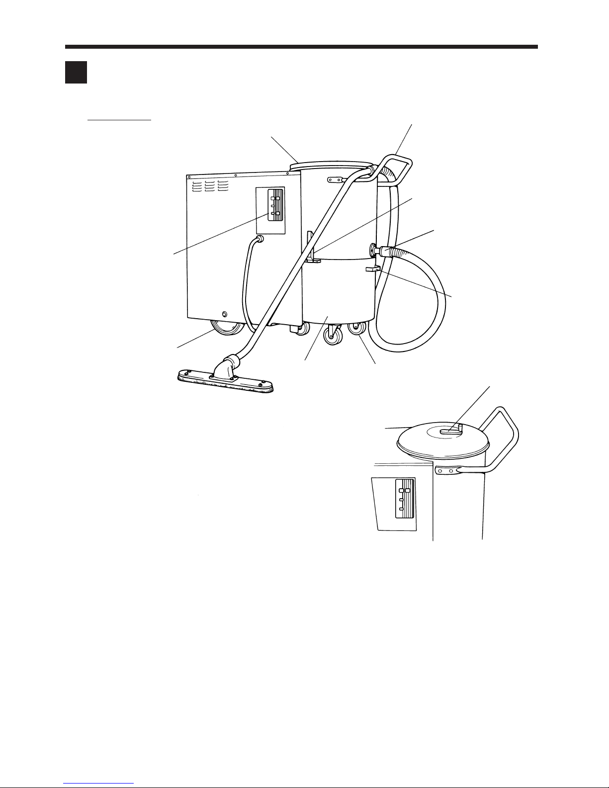
■Exterior
Bucket handle : Use this handle to mount or remove the bucket.
Tank cover : Remove the cover when you need to replace the
filter, inspect the vibrator, or clean a (cloth) filter.
Handle : Use the handle to move the cleaner.
Intake port : Connects to the dust vacuum hose.
Caster : The casters allow rolling of the bucket (when
bucket is removed), or the cleaner (while bucket is attached).
Bucket : Collects the vacuumed dust. You must periodically remove the bucket to empty out the dust.
Clamp : The 2 clamps hold the bucket in place.
Wheel : Supports movement of the cleaner.
Control panel : Provides the controls and indicator lamps that you use to operate and monitor the cleaner.
Manual handle : You rotate the handle to shake dust from the filter. (The handle is not included on models featuring
automatic shakeout.)
Tank cover
Handle
Clamp
Intake port
Bucket handle
Caster
Bucket
Wheel
Control panel
Manual handle
4
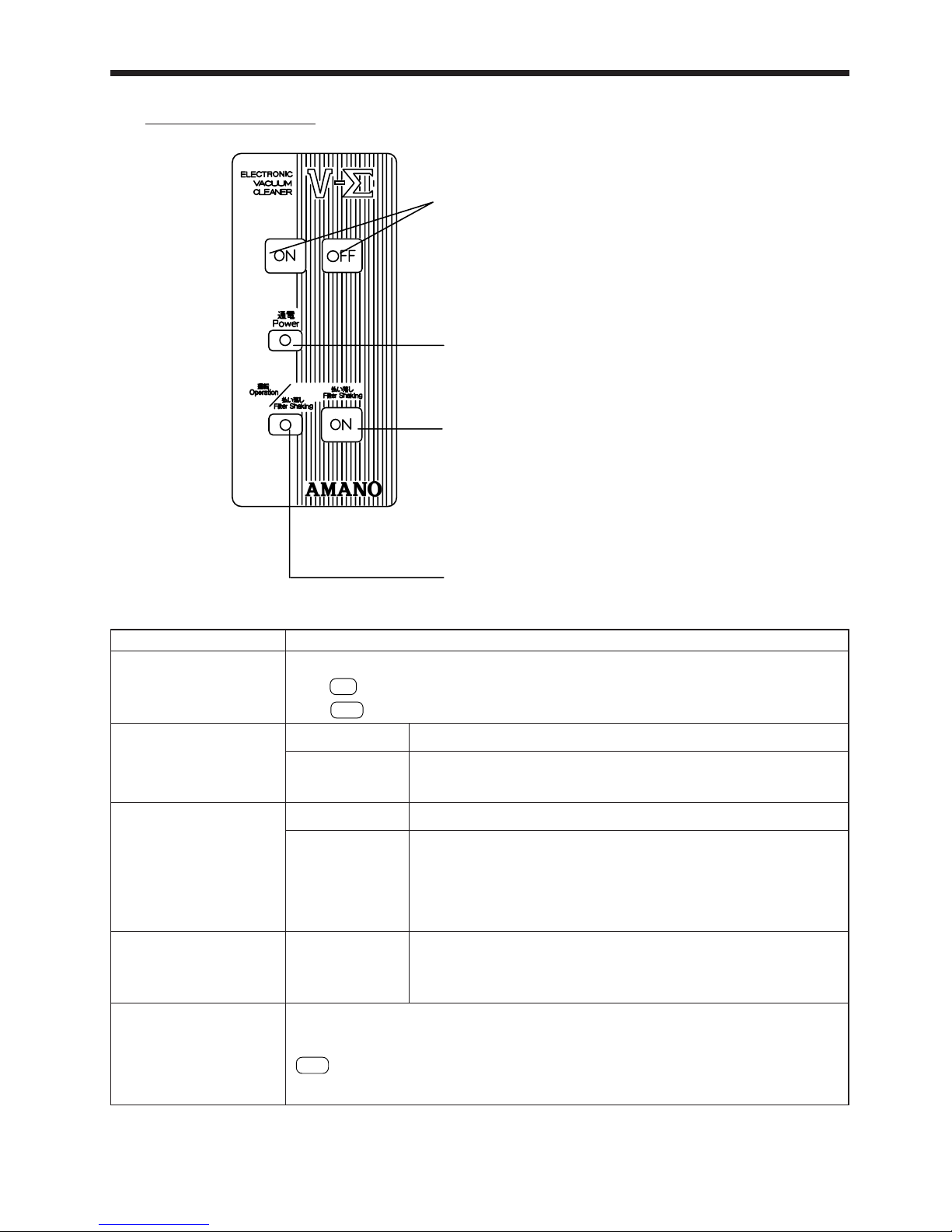
■Control Panel
Power Lamp
Turns ON (green) when power is sup-
plied and blinks (red) when there is a
power failure.
Operation Switch
Use this switch to start and stop.
Filter Shaking Switch
Enables you to shake the filter at will (only
on automatic shakeout type).
Operation / Filter Shaking Lamp
Turns ON (green) when the blower is operat-
ing and blinks (green) during filter shaking.
Function
These switches start and stop the motor.
Press
ON
to operate the fan motor.
Press
OFF
to stop the fan motor.
ON (green) Power ON
Blinking (red) Blinking at 0.5-second intervals indicates abnormal voltage.
Blinking at 1-second intervals indicates a reverse-phase operation.
ON (green) Fan operating
Blinking (green) Blinking at 1-second intervals indicates that the unit is standing by for a
filter shaking operation.
Blinking at 0.2-second intervals indicates that the unit is performing a
filter shaking operation.
ON (green) Fan operating
This is used for shaking down the dust adhering to the filter. Press the switch only for the
desired length of time. It does not function while the fan motor is rotating. Thus, press the
OFF
switch of the operation switch to stop the fan motor; then, press this switch. (However,
this switch is disabled for 1 minute after the operation is stopped.)
Functions of Lamps and Switches
Name
Operation Switch
Power Lamp
Operation / Filter Shaking
Lamp
(only on automatic
shakeout type)
Operation Lamp
(only on automatic
shakeout type)
Filter Shaking Switch
(only on automatic
shakeout type)
* The unit may stop running even if the power lamp is OFF. Refer to “Troubleshooting” on page 29 to identify the cause and
take a countermeasure in accordance with the troubleshooting chart.

5
Setting Up
■Operating Environment
Use the cleaner only in locations that meet the following conditions. Use of the cleaner in appropriate locations may result in
poor performance or machine breakage.
·Use the cleaner indoors only. It should not be directly exposed to rain, wind, or other adverse weather conditions.
·Do not use the cleaner in areas where it will be subjected to strong vibrations or impacts.
·The surface on which the product is installed should have ample strength to withstand the weight of the product.
·Keep the operating temperature between 0 and 40°C.
·When moving the product on a sloping surface, be careful not to topple it.
·Do not attempt to move the product on a steep slope, which can cause it to topple.
·Do not force the product over bumps, as this can cause the product to topple.
■Connection of Hose and Pipes
Accessories
(Accessories not included with some cleaners.)
●Unpacking the Accessories
The cleaner comes with the hose stored inside the bucket. When
you are ready to connect the hose, you must remove it from the
bucket as follows.
1Release the two clamps holding the bucket to the cleaner.
2Grasp the handle and gently lift and lean the cleaner so that it
is clear of the bucket.
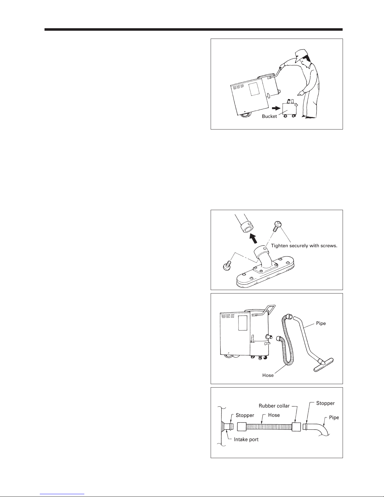
6
3Grasp the bucket handle and pull the bucket out toward you.
4Gently lower the cleaner (by its handle) until it is resting on
the floor.
5Take the hose out of the bucket.
6Once again, lift the cleaner by its handle, so that it is again
leaning forward.
7While still lifting the cleaner, grasp the bucket by the handle
and roll it back into place under the cleaner. Be sure to posi-
tion it correctly, with the bucket handle facing you.
8Gently lower the cleaner so that its tank area fits correctly
onto the bucket.
9Pull the two clamps (on the cleaner) over the clamp hooks on
the bucket. Fasten the clamps to lock the bucket in place.
The pipes and the intake port are packaged in a separate
cardboard box within the cleaner package. Remove them
from the box when you are ready to install them.
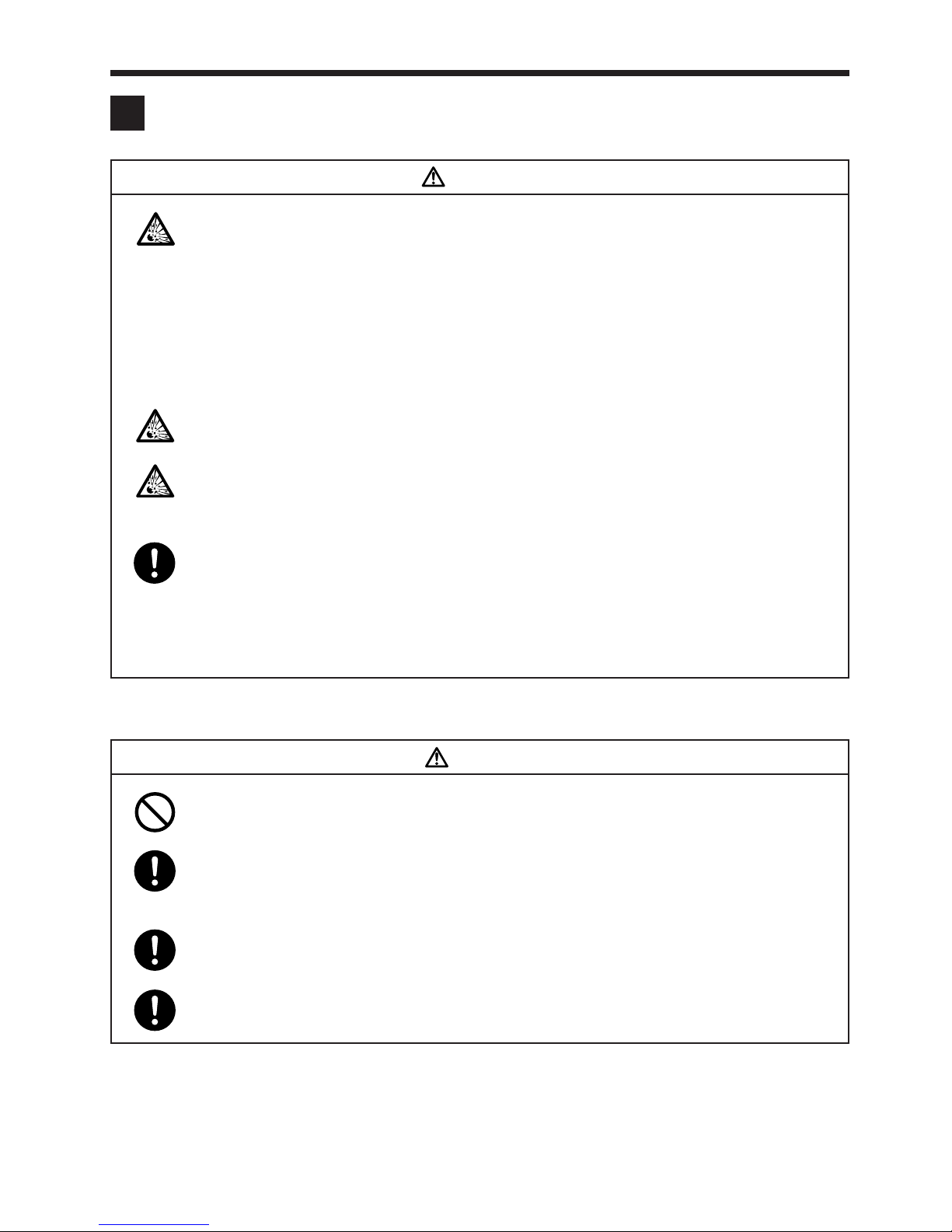
●Mounting the Accessories
1Fasten the floor-brush assembly to Pipe B using the screws.
2Connect up the hose.
Attach the hose to the intake port. Attach so that the rubber
collar on the hose fits over the stopper on the intake port.
Attach the other end of the host to the pipe. Again, make sure
that the rubber collar on the hose fits over the stopper on the
pipe.

7
Connecting the Power
This cleaner requires a 3-phase power supply. Before connecting up the power, make sure that your power supply matches the
power ratings given on the cleaner’s nameplate.
Warnings
•Be sure to use the rated voltage only. Do not place other loads on the same power
outlet.
Incorrect voltage or multiple loads may result in fire or electric shock.
•Never insert or remove the power cable while your hand is wet.
Doing so may result in electric shock.
•Do not allow the power cord to become damaged.
Do not let heavy objects rest on the cord, and do not pull it or excessively bend it. A damaged power cord may
result in fire or electric shock.
•Be sure to connect the ground.
If current leakage should occur due to failure to connect the ground, there is a risk of fire or electric shock.
There is also a risk that static electricity could cause damage to the equipment or faulty operation.
Cautions
•All wiring work must be performed by a competent electrician.
Failure to do so could cause accidents.
•Plug the cord into a 3-phase AC power outlet.
•Make sure that the ground is correctly connected.
•Perform a test run and check whether the “Power Lamp”is ON or OFF. If it blinks red at 1-second intervals, it indicates that
the three-phase power supply is reversed. If this occurs, you must rearrange the wire attachments within the power-cable
plug so that the phase is correct.
•Wait for more than 7 seconds after the primary power is supplied to the cleaner. During this time, the cleaner performs a self-
check (phase detection and power supply confirmation) and pressing the OPERATION
ON
switch will not start the cleaner.

8
Remote Control Setup
In addition to the operation of the switches on the control panel, this product can be operated with remote control. This feature
accepts operation signals from external sources such as a machine tool or a dedicated switch. If the product is ordered with the
selector switch for remote control, the selector switch and signal wire inlet are installed on the electrical control door.
To operate a standard model using remote control, because the selector switch is not included, order the switch from your dealer
or an Amano branch office.
■
Differences between standard model and model with selector switch
Standard Model With selector switch
Selector switch
(option) Signal wire
inlet

9
■Note
To operate the unit through remote control, perform the wiring and setup work described below.
■Function
The operation patterns described below can be selected by changing the settings of the levers 1 and 2 of the DIP switch
(SW1), which is mounted on the control panel. The setting procedures are described in the next page.
(Do not change the settings of levers 3 and 4 unless you have been specifically instructed to do so. Their initial settings vary
by model.)
For Your Information
•The wiring work for remote control must be performed by a licensed electrician.
External view of electrical control door
(Illustration: automatic shakeout type)
Selector switch
Internal view of electrical control door
Control panel
installation position
Control panel
Function
name
Pattern A
Pattern B
Pattern C
Pattern D
OFF
ON
OFF
ON
OFF
OFF
ON
ON
Selector switch
Lever
12
Yes
Yes
Yes
No/Yes
No
No
No
Description
Remote
Local
Remote
Local
Remote
Local
Enables the operation of the unit switch only. No remote
control.
Enables the operation of both the unit switch and the re-
mote-control switch.
Same as pattern A
Enables the operation of the remote-control switch only.
The unit switch is disabled.
Same as pattern A
The cleaner operates while the remote-control operation switch is ON. It
stops operating when the ON switch is disengaged. (The switch is the self-
holding type.) The operation switch on the unit is disabled. The shaking
switch is enabled both on the unit and on the remote-control switch.
Same as pattern A
·The default factory setting is “pattern B ”.
·A shaking switch is provided on the automatic shakeout type, and not on the standard (manual shakeout) type.
·“Pattern D ”enables the cleaner to operate in unison with another machine.

10
Checking
•For wiring, use a shielded cable with a minimum thickness of 0.3 mm2and a minimum withstand voltage of AC 250 V.
•The wiring for the remote-control switch must not be longer than 10 m.
•The terminal block outputs signals at DC10V, 10mA.
•Be sure to turn OFF the power supply before changing the DIP switch settings. Any changes made in the operation
patterns without turning OFF the power supply will be invalid.
•The minimum application load specification of switches and relays used for remote control must be below DC10V,
10mA.
1. Turn OFF the power supply at the source.
To ensure safety, turn OFF the power supply at the source.
2. Open the electrical control door.
Remove the two screws that are securing the electrical con-
trol door in place, and open the electrical control door.
3. Connect the wires.
Route the signal wires through the hole (ø16) in the electrical
control door and extend it to the terminal block. Follow the
wiring diagram on the next page to connect the signal wires
to the terminal block. To protect the signal wires, install the
supplied grommet in the hole.
Electrical
control door
Install the grommet
■
Wiring and Setup Work
Signal
wires
Terminal
block

11
4. Set up the functions.
Select the operation pattern to be used at DIP switch SW1 on
the control panel. (See page 9)
5. Perform a test run.
Supply power at the source. Push the switches to check that
they operate normally.
6. Close the electrical control door.
To ensure safety, turn OFF the power supply at the source.
Secure the electrical control door with two screws.
The operation switch to be used for function patterns B and C is a normally open type. The (ON/OFF) operation switch can be
operated at the touch of the switch. (* Once the contacts close, the circuit switches internally in the unit. Thus, it is unnecessary
to keep the contacts closed. Press the switch a minimum of 20 msec.)
For the operation switch in function pattern D, use a holding type switch (which operates when the contacts close, and stops
when the contacts open). For the filter shaking switch, use a normally open type switch for all patterns. The filter shaking
movement takes place while the filter shaking switch is being pressed (and the contacts are closed).
For patterns B, C
Selector switch (*1)
For pattern D
Selector switch (*1)
10 m max.
10 m max.
Shaking switch (*2)
Operation OFF switch
Operation ON switch
Remote-control switch
Shaking switch (*2)
Remote-control switch
Connect the wires while
pressing these buttons.
* 1: Closing the terminals No. 5 and 6 on the terminal block enables the unit to operate remotely. To operate remotely a standard
model without a selector switch, use a jumper wire to close the terminals No. 5 and 6 on the terminal block.
* 2: Mount the shaking switch only on the automatic shakeout type.
Operation switch
Connect the wires while
pressing these buttons.
* 1: Closing the terminals No. 5 and 6 on the terminal block enables the unit to operate remotely. To operate remotely a standard
model without a selector switch, use a jumper wire to close the terminals No. 5 and 6 on the terminal block.
* 2: Mount the shaking switch only on the automatic shakeout type.
12
Operating the Cleaner
Warnings
•Never use the vacuum to draw in any of the following materials.
·Explosive, flammable dust ..... Aluminum, magnesium, titanium, epoxy, organic solvents,
etc.
·Combustible materials ........... Gasoline, paint thinner, benzene, kerosene, paint, etc.
·Dust containing sparks ........... Dust produced by high-speed cutters, grinders, welding ma-
chines, etc.
·Fire remnants .......................... Cigarette stubs, ashes, etc.
·Liquids ..................................... Water, oil, liquid chemicals, etc.
Entry of any of the above materials into the cleaner may result in fire or explosion.
•Do not store the unit in hazardous areas specified by law.
Doing so may result in fire or explosion.
•Never operate the cleaner in the vicinity of flammable, corrosive, or explosive fumes
or gases.
Doing so may result in fire or explosion.
•If fire or explosion occurs within the machine, proceed as follows.
·Immediately cut off the power.
·Apply a suitable extinguishing agent.
·Do not open the tank lid and the bucket until the fire is extinguished and the internal tem-
perature lowers to the normal level.
Failure to carry out the above steps may result in a secondary explosion.
Cautions
•Do not operate the cleaner with its intake and exhaust ports blocked.
Blockage may cause overheating, resulting in fire.
•Switch off the power immediately if the machine begins to emit smoke, produce a
strange sound or odor, overheat, or vibrate abnormally.
Continued operation may lead to electric shock or fire.
•Switch off the power immediately if the motor stops during operation.
Leaving the power on may result in electric shock.
•Keep the intake air temperature between 0 and 40°C.
Failure to do so may result in equipment failure.
13
■Usage Precautions
Observe the following conditions during use. Failure to do so may cause the product to operate at reduced performance or
lead to a failure or an accident.
•This product is intended to be used as an industrial cleaner for collecting and recovering dust. Do not use it for purposes
other than those intended.
•Do not use the cleaner for collecting abrasive particles.
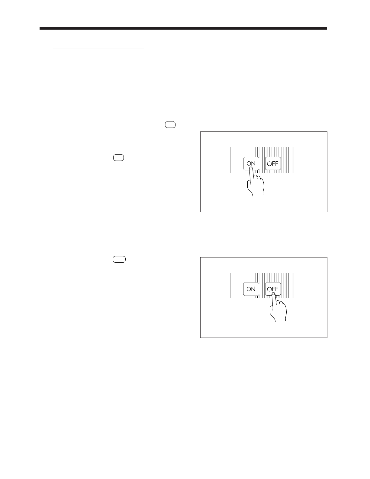
■Turning the Cleaner ON
Turn the cleaner ON by pressing the OPERATION
ON
switch.
This will cause the blower motor to start up, activating the vacuum.
Wait at least 7 seconds after the primary power is supplied to the
cleaner before pressing the
ON
switch. During this time, the
cleaner performs a self-diagnosis (power supply confirmation
and phase detection) and will not turn on even if the switch is
pressed.
The phases of the wires are reversed if the “Power Lamp”blinks
red at 1-second intervals while the blower motor remains
stopped. In this case you must disconnect the power and rewire
the power plug as described in P.14.
■Turning the Cleaner OFF
1. Press the OPERATION
OFF
switch to shut off the blower
motor.
If your model includes automatic shakeout (models V-2∑A,
V-3∑A, V-5∑A, and V-7∑A), it will remain in standby state
for 1 minute after the switch is pressed, and will then shake
out the filter for a period of 10 seconds.
2. Wait for filter shakeout to finish (if applicable), then discon-
nect the plug from the wall outlet.
3. Store the cleaner in a level area where it will be protected
from rain and wind.

14
■If the Blower Fails to Start
The phase sequence of the three phases is improper if the “Power Lamp”blinks red at 1-second intervals while the blower
motor remains stopped. In this case, you must use the following procedure to correct the problem.
1. Remove the power plug from the outlet.
The plug must be removed to ensure safety.
2. Swap the wiring connections inside the plug.
Remove the plug’s metal fitting, and expose the inside of the
plug as shown. Disconnect any two of the three leads (but not
the green lead, which is the ground) from their terminals, and
reverse the attachments. Retighten the leads securely.
3. Restart the machine.
Reassemble the plug, then insert it into the power outlet.
Press the OPERATION
ON
switch to start the blower mo-
tor. Make sure that the motor starts and the vacuum operates.
15
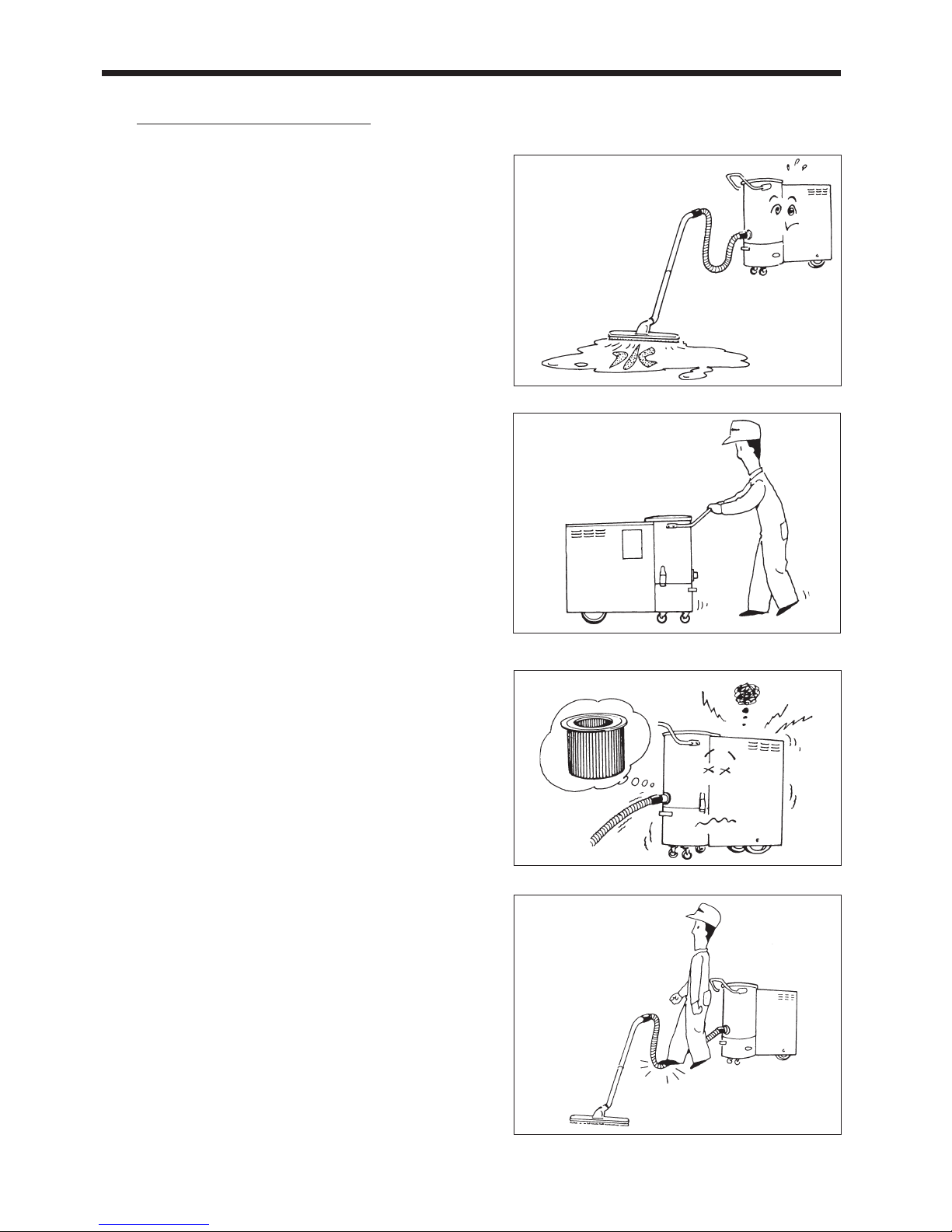
■Usage Precautions
•Do not use the cleaner to vacuum up water. Vacuuming of
water may result in breakage or electric shock.
•Always use the handle to move the cleaner. Pulling the
cleaner by the hose or by the power cord may damage the
hose or cord, or may cause the cleaner to move in an unex-
pected direction, resulting in accident.
•Never use the cleaner with a missing or broken filter —as
this will allow dust to enter the blower, leading to potentially
significant problems. Periodically check the filter’s condi-
tion, and be sure that is shaken clean as necessary.
•Do not step on the hose.
Stepping on the hose may change its shape, causing dust to
become clogged and reducing the hose’s service life.
•Do not use the cleaner with the power cord wrapped around
the handle or the cleaner itself. The area where the cord is
wrapped will heat up and may damage the cord, resulting in
an accident.
•Dispose of the dust in the bucket daily and do not allow it to
accumulate. A spark could ignite the dust, resulting in a fire.

16
■Never Run the Cleaner with the Hose Blocked
Air brought in through the hose is used to cool the blower. Oper-
ating the vacuum with the hose partially or completely blocked
will cause the blower to heat up, reducing its service life and
possibly leading to significant problems. Please make sure that
air flow is always sufficient.
In particular, guard against the following problems.
*Complete Blockage
Occurs when object is jammed in hose or other area, such that no
air can get through.
*Partial Blockage
Occurs when object stuck in hose or other area reduces the air
flow. (Air intake must not fall below approximately 1.0m3/min.)
■Never Operate under Excessive Load
Vacuuming in too much air causes the load on the motor to ex-
ceed its rated value. This type of overload will occur if you run
the cleaner with no hose attached, or if you attach a hose that is
wider than the one supplied with the cleaner.
Continued operation at overload conditions will trigger the ther-
mal relay, causing the blower to shut down. If this occurs, you
should cut off the power, then find the cause of the overload and
make the appropriate correction.
After correcting the problem and waiting at least 30 minutes
from time of shutdown, press the thermal relay’s RESET button
to reset the relay.
Table of contents
Other Amano Vacuum Cleaner manuals


Popular Vacuum Cleaner manuals by other brands


Evolution
Evolution R11 VAC Li Original instructions

Vax
Vax INFINITY V-116B instruction manual

Black & Decker
Black & Decker UV800B instruction manual

Dynabrade
Dynabrade RaptorVac 61202 Safety, operation and maintenance instructions

Sanitaire
Sanitaire SC886-E Repair parts list

Eldom
Eldom OS1500 Instructions for use