AmazonBasics B07J4VK742 Operating and safety instructions

Handleset
Juego de Manillas
Poignées

Tulip Knob
B07J4VK742, B07J51RF8M, B07J4HXTVX, B07J51DNTR
Shelby Lever
B07J4VQCLV, B07J4HY1NC, B07J4HXZJ1, B07J51RF99
English ..................................... 3
Español.................................. 15
Français ................................. 27

3
Welcome Guide •English
Contents:
Before getting started, ensure the package contains the following components:
Ax1 Gx1
Bx1 Hx2
Cx1 Ix2
Dx1 Jx1
Ex1 Kx8
Fx2 Lx1

4
Optional
You will need:
Screwdriver
Tape measure
5
Before First Use
• Check for transport damage.
Risk of suffocation! Keep any packaging materials away from children – these
materials are a potential source of danger, e.g. suffocation.
Installation
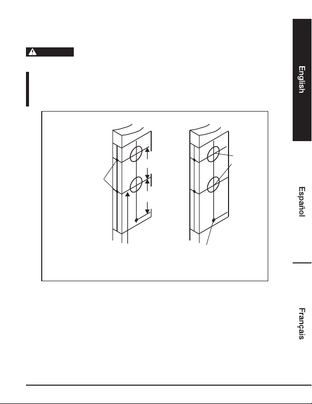
Step 1: Mark Door
Make a mark for a
1” (25.4 mm) hole
on the center of the
door edge.
Height 36” to 38"
(914 mm - 965 mm)
from the floor
Make a mark for a 3/8"
(10 mm) hole on the door
face.
5” (127 mm)
8-7/16” (214 mm)
2-1/8”
(54 mm)
hole
• Use the template enclosed to mark holes on the door face.
DANGER

6
Installation
Step 2: Drill Holes
3/8” (10 mm) hole
2-1/8” (54 mm) holes
1” (25.4 mm) holes
1. Drill 2-1/8” (54 mm) holes from both sides of the door.
2. Drill 1” (25.4 mm) holes in the door edge for the latch.
3. Drill a 3/8” (10 mm) hole for the mounting screw of the exterior handle.
4. To avoid splintering, drill holes from both sides.

7
Installation
Step 3 (optional): Adjustable Latch for Top Deadbolt
1
2Drive-in latch
To change latch faces
1. Use a flat-head screwdriver to separate the face plate from back plate.
2. Snap the selected face plate onto the back plate.
Drive-in installation
• Make sure the round face plate is properly aligned as illustrated and snap it to the latch case.
2-3/4” (70 mm)
Latch backset adjustment
• Rotate the latch case as illustrated for a backset of 2-3/4” (70 mm) or in reverse direction for
a backset of 2-3/8" (60 mm).

8
Installation
Step 4 (optional): Adjustable Latch for Bottom Handle
Latch
3
Correct Wrong
1. If a 2-3/4” (70 mm) backset is required, pull the spindle cam all the way to the right edge of the
adjustment hole.
2. Make sure the 2-3/4” (70 mm) cam hole is properly aligned.
3. Your latch is now set for a 2-3/4” (70 mm) backset. To reset the latch to a 2-3/8” (60 mm)
backset, push the spindle cam to the left end of the adjustment hole.
1
2
Latch face plate
• Determine which latch-mounting method will be used and make necessary adjustments.
• No adjustment is required for the square latch face plate.
Changing latch faces
1. Use a flat screwdriver to separate the face plate.
2. Snap the selected face plate onto the back plate.

9
Drive-in face plate installation
• Remove the original face plate.
Align the round face plate with the latch bolt and push it inside the latch bolt until you hear the
catch click.
Step 5: Install Latches
Bottom
handle latch
Top deadbolt
latch
Chisel 1/8"
(3 mm) deep
1. Insert the latches in the holes, parallel to the edge of the door. Mark the outline and remove the
latch.
2. Chisel 1/8” (3 mm) deep or until the latch face is flush to the door edge. Note: the cut-out must
be parallel to the edges of the door.
3. Insert the bottom latch and secure it with the wood screws.

10
Installation
Step 6: Install Exterior Handle
Exterior
handle
Square
spindle
Stems
• Place the exterior handle with the stems and square spindle into the latch as shown. Press
tightly against the door face.
Step 7: Install Interior Handle
Interior lever
Bottom screw and washer
Interior knob
For single handle
• Secure and fasten the interior mechanism firmly using screws as shown in the figure.
This manual suits for next models
7
Table of contents
Languages:
Popular Door Lock manuals by other brands


Dorma
Dorma MUNDUS PREMIUM GK 50 Mounting instruction

SCOOP
SCOOP Pullbloc 4.1 FS Panik Assembly instruction

Yale
Yale MORTISE 8800 SERIES installation instructions

Siegenia
Siegenia KFV AS3500 Assembly instructions

Saflok
Saflok Quantum ädesē RFID installation instructions

ArrowVision
ArrowVision Shepherd 210 installation manual