AmazonBasics B089R7J1CQ User manual

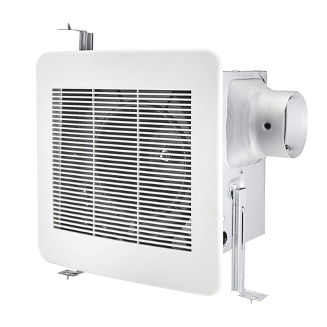
3-Inch Bathroom Exhaust Fan, 70 CFM, 2 Sone, White
3-Ventilateur d’Évacuation d’Air de 11 Pouces pour Salle de Bains,
70 CFM, 2 Sones, Blanc
3-Extractor de Baño de 11 Pulgadas, 70 CFM, 2 Sones, Blanco
B089R7J1CQ

English ..................................... 3
Español .................................... 16
Français ................................... 29

Welcome Guide •English
Part List
Parts Description Qty
AFan Housing x1
Bx1
C
D
E
x1
Grille
Quick Connect Wire Connector x3
Wood Screw (M4x30 mm) x4
Duct Connector
B
A
C
D
E
Contents:
Before getting started, ensure the package contains the following components:
When using in existing construction, for proper installation it is
recommended that you have attic access or access above the installation
location.
Recommended Tools and Supplies: Recommended Fittings:
• 3/8 in. Trade Size with 1/2 in. Knockout
Wire Clamp
• Phillips Screwdriver
• Safety Glasses
• Utility Knife/Drywall Saw
• Duct Tape or Clamps
• Hammer (Optional)
• Drill (Optional)
• Drill Bits (Optional)
NOTICE
3

IMPORTANT SAFEGUARDS
Read these instructions carefully and retain them for future use. If this
product is passed to a third party, then these instructions must be included.
PLEASE READ AND UNDERSTAND THIS ENTIRE MANUAL
BEFORE ATTEMPTING TO ASSEMBLE, OPERATE, OR INSTALL
THE PRODUCT.
SAFETY INFORMATION
Always disconnect the power supply prior to servicing the fan, motor, or junction box.
Follow all local building, safety, and electrical codes as well as NEC (National Electrical
Code) and OSHA (Occupational Safety and Health Act).
•
•
Electric Service supply must be 120 volts, 60 hertz.
•This product must properly connect to the grounding conductor of the supply circuit.
•Do not bend or kink the power wires.
•Do not use this fan with any solid state control device, such as a remote control,
dimmer switch, or certain timers. Mechanical timers are not solid state devices.
•
Do not install in a ceiling with insulation greater than R40.
•
TO REDUCE THE RISK OF FIRE, ELECTRIC SHOCK, OR INJURY
TO PERSONS, OBSERVE THE FOLLOWING:
Duct work should be installed in a straight line with minimal bends.
Use this unit in the manner intended by the manufacturer. If you have
any questions. Please call customer service.
•Duct work size must be the same size as the exhaust flange and should not be reduced.
Reducing the duct size may increase fan noise.
•
If this unit is to be installed over a tub or shower, it must be marked as a appropriate
for the application. When the fan is going to install in the bathroom, the fan and the
tub need to be more than 1.0 meter between each other, the fan required to install
at the other side of the tub in ceiling. Acceptable for use over a bathtub or shower
when installed in a GFCI protected branch circuit.
•
WARNING
Before servicing or cleaning unit, switch power off at service panel
and lock the service disconnecting means to prevent power from
being switched on accidentally. When the service disconnecting
means cannot be locked, securely fasten a prominent warning device,
such as a tag, to the service panel.
WARNING
Installation work and electrical wiring must be done by a qualified
person(s) in accordance with all applicable codes and standards,
including fire-rated construction.
WARNING
When cutting the ceiling, do not damage electrical wiring and other
hidden utilities.
WARNING
Ducted fans must always be vented to the outdoors.
WARNING
Sufficient air is needed for proper combustion and exhausting of
gases through the flue (chimney) of fuel burning equipment to prevent
backdrafting. Follow the heating equipment manufacturer’s guideline
and safety standards such as those published by the National Fire
Protection Association (NFPA), and the American Society for Heating,
Refrigeration and Air Conditioning Engineers (ASHRAE) and local code
authorities.
WARNING
4

Before First Use
•Check for transport damage.
Risk of suffocation! Keep any packaging materials away from children
– these materials are a potential source of danger, e.g. suffocation.
DANGER
Airflow: 70 CFM Power Consumption: 25W
Gross Weight: 6.42 lbs.
Ceiling Opening: 7.3 in. (L) x 7.5 in. (W)
Duct Output: 3" Required
Electric Service: 120V, 60Hz
Duct Diameter: 3 in.
Sound Output: 2.0 Sone
Specifications
•
Ensure ducting from fan to the outside of structure uses the shortest and straightest
route for best performance. Not doing so can restrict air flow and increase noise and
energy usage. Never reduce the recommended ductwork size. Fans using existing
ducting may not achieve full air flow ratings.
•
Ensure to follow the “Not Recommended” examples above when installing duct work to
ensure proper ventilation.
•Ensure duct joints and exterior penetrations are sealed with caulk or other similar
material to create an air-tight path and to minimize structure heat loss and gain and
reduce the potential for condensation.
•
Wrapping duct with insulation can minimize possible condensation buildup, heat loss,
heat gain and inhibit mold growth.
Typical Installation
Fan housing
Duct
Roof cap
Eave vent
Wall cap
Eave
Roof
Wall
Fan housing
Duct
Too sharp of bend
Fan
body
Minimum 18"
Avoid duct shrink
Too many bends
Elbow near the body
RECOMMENDED
Not Recommended
Typical Installation
Duct
Fan housing
Fan
Housing
Minimum 18"
Not Recommended
5

• Strip all wires so 3/8 in. – 1/2 in. of the copper wire is exposed.
• Firmly grip wire and insert stripped end of wire into open port of quick connect wire
connector. Only insert one wire per port. Wires should only be inserted into quick
connect wire connectors that have same color wire covering.
• Ensure stripped end of wires are tight and fully inserted to back of connector.
Pre-Installation
WIRING DIAGRAMS
Quick Connect Wire Connectors INSTRUCTIONS
To be sold only with installation instructions.
HOUSE WIRES
PRODUCT WIRES
QUICK CONNECT
WIRE CONNECTOR
Wiring must comply with all applicable electrical codes. Turn OFF
power at the service panel before removing or installing connectors.
WARNING
COPPER TO COPPER ONLY. Do not use Aluminum wire.
Quick Connect Wire Connectors installation should follow the
instructions below.
Quick Connect Wire Connectors are reusable on solid wires of the
same wire gage or smaller. Do not reuse the connector on stranded
wires.
WARNING
CAUTION
NOTICE
The acceptable solid wire range is 12-18 AWG.
NOTICE
QUICK CONNECT
WIRE CONNECTOR
PRODUCT
WIRES
HOUSE
WIRES
TO SWITCH
TO NEUTRAL
TO GROUND
Junction box
FAN HOUSING
Green wire
MOTOR
CAPACITOR FOR
LONG LIFE OF
MOTOR
Automatic terminal switch
Black wire
White wire
6

• Place the fan housing (A) next to a celling
joist.The fan housing should be level and
perpendicular to the joist.
Installation - New Construction
Step 1: Fan housing placement
Make sure power is switched off at service panel before starting installation.
CAUTION
Unit is designed for ceiling installation only.
NOTICE
A
1
2 4 6 8 10 12 14
16 18 20
35791113
151719
O
N
O
N
O
F
F
O
F
F
O
N
O
F
F
O
N
O
N
O
F
F
O
N
O
F
F
O
N
O
F
F
O
N
O
F
F
O
N
O
F
F
O
N
O
F
F
O
N
O
F
F
O
N
O
F
F
O
F
F
O
N
O
F
F
O
N
O
F
F
O
N
O
F
F
O
N
O
F
F
O
N
O
F
F
O
N
O
F
F
O
N
O
F
F
CEILING JOIST
• Carefully remove the unit from the carton.
• Inspect duct work and wiring before proceeding with installation.
• You may need the help of a second person to install this fan. One person on the attic
side and one on the room side.
• Ensure area above installation location is clear for proper wiring and duct work for
fan installation and future maintenance.
Pre-Installation
Before installing product, make sure all parts are included. Compare parts with parts list
contents on page 3. If any parts were not included or damaged, do not attempt to install
the product.
Turn off electricity at the service panel before beginning installation.
WARNING
Replacement fan installations may vary due to how previous fans were
installed. Tools and supplies needed for proper installation are not
included but can be found at home improvement and hardware stores.
NOTICE
7

• Mount the fan housing (A) to the joist
using wood screws (E) where indicated.
•
Installation - New Construction
Step 2: Mount the fan housing
Step 3: Connect house and fan wires
White
White
D
Black
Black
D
Green/Copper
Green/Copper
D
FIG 1
FIG 2
E
E
A
CEILING JOIST
Remove screw from junction box cover and
remove cover from junction box on
the fan housing. Note how flange on bottom
of cover is positioned (FIG 1).
It is recommended to use a
3/8 in. trade size with 1/2 in. knockout wire
clamp to secure wiring to junction box cover.
Black/red wires are typically
“hot”. White wires are typically “common”.
Green or bare copper wires are typically
“ground”. Do proper electrical testing if
uncertain and/or consult an electrical
contractor.
If electrical wires from service
switch do not match wiring from fan housing,
you must determine what each wire represents
before making wire connections. Consult an
electrical contractor if uncertain.
• Pull wires through hole of junction box cover.
Using quick connect wire connectors, connect
all electrical wiring from service switch to
wiring from fan housing. If needed, refer to
page 6 on using quick connect wire connectors.
NOTICE
CAUTION
NOTICE
8

Step 3: Connect house and fan wires
Step 4: Duct Installation
Installation - New Construction
Step 5: Grille Installation
FIG 3
B
CEILING
3 IN. DUCT
DUCT TAPE
OR CLAMP • Attach 3 in. circular flexible duct to fan
housing duct flange and secure with duct
tape or clamps (not included).
• When all wires are connected properly,
carefully place all wiring with quick connect
wire connectors into junction box.
Install junction box cover back onto junction
box and install screw. Ensure bottom of
cover flange is inserted correctly. (FIG 3)
Before moving on to the
grille installation, complete all ceiling work.
Ceiling cutout should align with edge of
fan housing.
• Pinch the spring clips and insert the
grille (B) into narrow rectangular slots
inside of the fan housing next to the
fan motor.
• Turn on power source. Check fan for
abnormal sounds or vibration.
NOTICE
9

Installation - Existing Construction
Step 2: Measure the ceiling opening
Step 1: Remove the existing fan
1
2 4 6 8 10 12 14
16 18 20
35791113
151719
O
N
O
N
O
F
F
O
F
F
O
N
O
F
F
O
N
O
N
O
F
F
O
N
O
F
F
O
N
O
F
F
O
N
O
F
F
O
N
O
F
F
O
N
O
F
F
O
N
O
F
F
O
N
O
F
F
O
F
F
O
N
O
F
F
O
N
O
F
F
O
N
O
F
F
O
N
O
F
F
O
N
O
F
F
O
N
O
F
F
O
N
O
F
F
CAUTION
• Measure the opening to ensure it is
large enough to accommodate the
new fan body (A) (7.3 in. x 7.5 in.).
•
•
Remove existing fan cover and fan housing.
Disconnect all venting and electrical.
7.5 in. side of opening
should be flush with joist. If opening is
not large enough see step 3.
NOTICE
It may be easier to remove
existing fan from above or attic access.
NOTICE
If existing wiring colors from the service switch
are not black, white and green/bare copper,
note how electrical connections were made.
Make sure power is switched off at service panel before starting
installation. Determine if you have above or attic access.
10

Step 5: Mount the fan housing
Installation - Existing Construction
Step 3: Enlarging the opening (optional)
7.5"
7.3"
Step 4: Fan housing placement
A
E
E
A
•
• Place the fan housing (A) next to a ceiling
joist or wall stud. The fan housing should
be level and perpendicular to the joist
or stud.
• Mount the fan housing (A) to the joist
using wood screws (E) where
indicated.
Make sure 7.5 in. side
of opening is flush with joist.
All work from this point on
should be completed from attic or space
above installation area. You may need a
second person below to hold fan housing
in place until secured.
Using a drywall saw or utility knife, cut
drywall or ceiling material out to make
the new size opening.
NOTICE
NOTICE
CEILING JOIST
CEILING JOIST
• All existing and new hole cut outs need to
be 7.3 in. x 7.5 in. For existing holes that
are smaller, enlarge hole to new size.
11

Step 6: Connect house and fan wires
Installation - Existing Construction
D
D
D
FIG 1
FIG 2
FIG 3
WHITE
WHITE
BLACK
BLACK
GREEN/
COPPER GREEN/
COPPER
•Remove screw from junction box cover and
remove cover from junction box on
the fan housing. Note how flange on bottom
of cover is positioned (FIG 1).
It is recommended to use a
3/8 in. trade size with 1/2 in. knockout wire
clamp to secure wiring to junction box cover.
Black/red wires are typically
“hot”. White wires are typically “common”.
Green or bare copper wires are typically
“ground”. Do proper electrical testing if
uncertain and/or consult an electrical
contractor.
If electrical wires from service
switch do not match wiring from fan housing,
you must determine what each wire represents
before making wire connections. Consult an
electrical contractor if uncertain.
• Pull wires through hole of junction box cover.
Using quick connect wire connectors, connect
all electrical wiring from service switch to
wiring from fan housing. If needed, refer to
page 6 on using quick connect wire connectors.
NOTICE
CAUTION
NOTICE
• When all wires are connected properly,
carefully place all wiring with quick connect
wire connectors into junction box.
Install junction box cover back onto junction
box and install screw. Ensure bottom of
cover flange is inserted correctly. (FIG 3)
12

Step 7: Duct Installation
Installation - Existing Construction
Step 8: Install the grille
B
CEILING
3 IN. DUCT
DUCT TAPE
OR CLAMP • Attach 3 in. circular flexible duct to fan
housing duct flange and secure with duct
tape or clamps (not included).
• Pinch the spring clips and insert the
grille (B) into narrow rectangular slots
inside of the fan housing next to the
fan motor.
• Turn on power source. Check fan for
sounds or vibration.
13

WARNING
TROUBLESHOOTING
Possible Cause
Problem Solution
The fan
seems
louder than it
should.
The fan is not
clearing the
room.
The CFM is too great.
The fan exhaust flow is reduced to fit a
smaller duct.
The fan body is not attached securely.
Use the recommended size ducting to
reduce fan noise.
Be sure the fan is securely attached to
the ceiling joists.
The damper is damaged or not working
properly.
The bend in the duct is too close to the
fan exhaust flange.
Be sure the CFM rating on the fan
matches the square footage of your room.
Be sure you do not have any sharp
bends in the duct closer than 18 in. to
the fan .
Check the damper to ensure it is opening
and closing properly. If the damper has
become damaged, please call Customer
Service.
Be sure a door or window is slightly ajar
or opened to allow airflow. The fan is not
able to draw air out of the room without
enough airflow to draw from.
Be sure the CFM rating on the fan
matches the requirements for your room
size.
There is insufficient airflow intake in the
room.
There is insufficient CFM.
Using a tissue is not the
correct method for determining if the fan
is operating properly. If the fan clears
steam from the room within approximately
15 minutes of completing your shower,
then the fan is operating properly.
Cleaning and Maintenance
•
•
•
•
•
Routine maintenance should be done at least once a year.
Never use solvents, thinner or harsh chemicals to clean fan.
Do not allow water to enter the motor.
Do not immerse metal parts in water.
Use a mixture of mild soap and water to gently remove dust or dirt from fan
and cover.
• See “Important Safety Information” on page 4 before proceeding.
NOTICE
Shut power off at service panel before servicing.
14

Warranty Information
To obtain a copy of the warranty for this product:
US: Visit amazon.com/AmazonBasics/Warranty
US: +1-866-216-1072
Feedback and Help
Love it? Hate it? Let us know with a customer review.
AmazonBasics is committed to delivering customer-driven products that live up to
your high standards. We encourage you to write a review sharing your experiences
with the product.
US: amazon.com/review/review-your-purchases#
US: amazon.com/gp/help/customer/contact-us
15

Guía de Bienvenida •Español
Lista de
Partes Descripción Cant.
ACarcasa del ventilador x1
Bx1
C
D
E
x1
Rejilla
Conectores para cables de conexión rápida x3
Tornillos de madera (M4 x 30 mm) x4
Conector de ducto
B
A
C
D
E
Contenido:
Antes de empezar, asegúrese de que la caja contenga los siguientes componentes:
Al usar en una construcción ya existente, recomendamos tener acceso
al ático o a un área por sobre el lugar de instalación.
Herramientas y suministros recomendados:
Uniones recomendadas:
• Abrazadera para cables de 3/8
pulgadas nominal, con conector
de 1/2 pulgadas
• Destornillador Phillips
• Antiparras de seguridad
•
Cuchillo utilitario/sierra para yeso-cartón
• Cinta adhesiva o abrazaderas
• Martillo (opcional)
• Taladro (opcional)
• Brocas (opcionales)
AVISO
16

PRECAUCIONES IMPORTANTES
Lea atentamente estas instrucciones y guárdelas para usarlas más adelante.
En caso de entregar este producto a un tercero, también se deben incluir
estas instrucciones.
LEA Y COMPRENDA ESTE MANUAL COMPLETO ANTES DE
INTENTAR ENSAMBLAR, USAR O INSTALAR EL PRODUCTO.
INFORMACIÓN DE SEGURIDAD
Desconecte siempre el suministro de alimentación antes de reparar el motor,
ventilador o caja de conexión.
Siga todos los códigos locales de construcción seguridad y electricidad, además del
NEC (código eléctrico Nacional) y la OSHA (Ley de seguridad y salud ocupacional).
•
•
El suministro del servicio eléctrico debe ser de al menos 120 volts, 60 Hz.
•Este producto debe conectarse de forma adecuada al conductor a tierra del circuito
de alimentación.
•
No pliegue ni doble los cables de alimentación.
•No use este ventilador junto a algún dispositivo de control de estado sólido, como
un control remoto, interruptor atenuador o ciertos temporizadores. Los temporizadores
mecánicos no son dispositivos de estado sólido.
•
No instale en un techo con una aislación superior a R40.
•
PARA REDUCIR EL RIESGO DE INCENDIO, DESCARGA ELÉCTRICA
O LESIONES A PERSONAS, TENGA EN CUENTA LO SIGUIENTE:
Use esta unidad de la manera indicada por el fabricante. Si tiene
alguna pregunta. Llame al servicio de atención al cliente.
Los ductos se deben instalar en línea recta, con desviaciones mínimas.
•Los ductos deben ser del mismo tamaño que la brida del extractor y no reducirse.
Reducir el tamaño del ducto puede aumentar el nivel de ruido del ventilador.
•
Si esta unidad se instalará sobre una ducha o tina, debe tener marca de adecuada
para la aplicación. Cuando el ventilador se vaya a instalar en el baño, éste y la tina
deben estar a más de 1.0 metros de distancia entre sí, donde el ventilador debe
instalarse al otro lado de la tina, en el techo. Se puede usar sobre una tina o ducha al
instalarse en un circuito derivado con protección GFCI.
•
Antes de reparar o limpiar la unidad, apáguela desde el panel de
servicio y desconéctela de la energía para evitar que se encienda por
accidente. Cuando no sea posible bloquear el corte de la energía, fije
un dispositivo de advertencia fácil de notar, como una etiqueta, al
panel de servicio.
La instalación y el cableado se deben llevar a cabo mediante una
persona calificada, siguiendo todos los códigos y normas aplicables,
incluidas aquellas relacionadas con construcciones antiincendios.
Al cortar el techo, no dañe los cableados eléctricos ni otras líneas de
servicio.
Los ventiladores conectados a ductos siempre deben desembocar
hacia el exterior.
Para evitar una contracorriente, se requiere un flujo de aire suficiente
para la correcta combustión y escape de gases a través del
cañón (chimenea) del equipo que queme combustible. Siga las pautas
del fabricante del equipo calefactor y las normas de seguridad, como
las publicadas por la Asociación Nacional de Protección Contra
Incendios (NFPA, por sus siglas en inglés), por la Sociedad Americana
de Calefacción, por los Ingenieros de Refrigeración y Aire
Acondicionado (ASHRAE, por sus siglas en inglés) y aquellas publicadas
en los códigos locales por las autoridades pertinentes.
ADVERTENCIA
ADVERTENCIA
ADVERTENCIA
ADVERTENCIA
ADVERTENCIA
ADVERTENCIA
17

Antes de usar por primera vez
•Compruebe que no haya daños causados por transporte.
¡Riesgo de asfixia! Mantenga los materiales de empaque lejos de los niños.
– estos materiales son una posible fuente de peligro; por ejemplo, de asfixia.
PELIGRO
Flujo de aire: 70 CFM Consumo energético: 25 W
Peso bruto: 6.42 lb.
Abertura del techo: 7.3 pulgadas (L) x 7.5 pulgadas (An)
Salida del ducto: 3 pulgadas
Red eléctrica: 120 V, 60 Hz
Diámetro del ducto: 3 pulgadas
Generación de ruido: 2.0 sones
Especificaciones
•
Para lograr un máximo desempeño, asegúrese de que los ductos que conectan al
ventilador con la parte exterior de la estructura usen la ruta más corta y recta posible.
No hacer esto puede restringir el flujo de aire y aumentar tanto el ruido como el uso
energético. Jamás reduzca el tamaño recomendado para los ductos. Los ventiladores
que usen los ductos actuales podrían no cumplir con el máximo de flujo de aire que
son capaces de proporcionar.
•
Asegúrese de seguir los ejemplos de la sección “No recomendado” que aparece
anteriormente al instalar ductos, para así garantizar una ventilación adecuada.
•Asegúrese de que las penetraciones exteriores y las uniones de los ductos estén sellados
con sellante u otro material similar para crear una vía hermética y así minimizar la variación
de la temperatura estructural y reducir el potencial de condensación.
•
Enrollar al ducto con aislante puede minimizar la acumulación de posible condensación,
pérdida de calor, calentamiento e inhibir el crecimiento de moho.
Instalación típica
Carcasa del
ventilador
Ducto
Carcasa del
ventilador
Ducto
Carcasa del
ventilador
Ducto
Tapa del techo
Ventila del alero
Tapa de la pared
Alero
Techo
Pared
Evite reducir el
diámetro del ducto
Demasiados dobleces
Fan
body
Mínimo
18 pulgadas
Dobles demasiado
agudos
Codo cerca de la unidad
RECOMENDADO
No recomendado
Carcasa
del
ventilador
18

• Pele todos los cables de manera tal que 3/8 - 1/2 pulgadas del cobre quede expuesto.
• Sujete el cable con firmeza e inserte el extremo pelado del cable hacia el puerto abierto
del conector para cables de conexión rápida. Inserte solo un cable por puerto. Los
cables solo se deben insertar hacia los conectores de conexión rápida que tengan la
cobertura del mismo color.
• Asegúrese de que los extremos pelados de los cables estén firmes e insertados por
completo hacia la parte posterior del conector.
Preinstalación
DIAGRAMAS DE CABLEADO
Conectores para cables de conexión rápida INSTRUCCIONES
Se ende solo con instrucciones de instalación.
CABLES DE LA CASA
CABLES DEL
PRODUCTO
DE CONEXIÓN RÁPIDA
CONECTOR PARA CABLES
Caja de conexión
El cableado debe cumplir con todos los códigos eléctricos aplicables.
Corte la electricidad desde el panel de energía antes de sacar o instalar
conectores.
ADVERTENCIA
ADVERTENCIA
SOLO COBRE A COBRE. No use cable de aluminio.
La instalación de los conectores para cables de conexión rápida se
debe realizar según las siguientes instrucciones.
Los conectores para cables de conexión rápida se pueden reutilizar
sobre cables sólidos del mismo calibre o inferior. No reutilice el
conector sobre cables trenzados.
PRECAUCIÓN
AVISO
El calibre aceptable para un cable sólido es 12-18 AWG.
AVISO
CONECTOR PARA CABLES
DE CONEXIÓN RÁPIDA
PRODUCTO
CABLES CARCASA
CABLES
A INTERRUPTOR
A NEUTRO
A TIERRA
CARCASA DEL VENTILADOR
MOTEUR
CONDENSADOR
PARA
EXTENDER LA
VIDA ÚTIL DEL
MOTOR
Interruptor de
terminal automático
Caja de conexión
Cable negro
CAJA DEL INTERRUPTOR
19

• Coloque la carcasa del ventilador (A) junto
a una viga del techo. La carcasa del
ventilador debe quedar nivelada y
perpendicular a la viga.
Instalación en una construcción nueva
Paso 1: instalación de la carcasa del ventilador
Asegúrese de que la energía esté desconectada en el panel de servicio
antes de la instalación.
La unidad está diseñada solo para instalarse en techos.
A
1
2 4 6 8 10 12 14
16 18 20
35791113
151719
O
N
O
N
O
F
F
O
F
F
O
N
O
F
F
O
N
O
N
O
F
F
O
N
O
F
F
O
N
O
F
F
O
N
O
F
F
O
N
O
F
F
O
N
O
F
F
O
N
O
F
F
O
N
O
F
F
O
F
F
O
N
O
F
F
O
N
O
F
F
O
N
O
F
F
O
N
O
F
F
O
N
O
F
F
O
N
O
F
F
O
N
O
F
F
VIGA DEL TECHO
• Saque cuidadosamente la unidad del cartón.
• Inspeccione los ductos y cables antes de seguir con la instalación.
• Podría necesitar la ayuda de una segunda persona para instalar este ventilador. Una
persona del lado del ático y otra del lado de la habitación.
• Asegúrese de que el área sobre el lugar de instalación esté despejada para así realizar
un cableado e instalación de ductos correcto para el ventilador, además de permitir la
realización de mantenimiento a futuro.
Preinstalación
Antes de instalar el producto, asegúrese de que todas las piezas estén incluidas.
Compare las piezas con la lista de partes de la página 3. Si hay alguna parte faltante o
dañada, no intente instalar el producto.
Corte la electricidad desde el panel eléctrico antes de comenzar la instalación.
La instalación de ventiladores de repuesto puede variar según cómo se
instalaron los ventiladores anteriores. Las herramientas y suministros
necesarios para una instalación adecuada no se incluyen, pero se
pueden adquirir en ferreterías y tiendas de herramientas.
ADVERTENCIA
AVISO
PRECAUCIÓN
AVISO
20
Table of contents
Languages:
Other AmazonBasics Fan manuals