AmazonBasics AT-7034MSK User manual

Pneumatic Air Angle Die Grinder Kit - 28-Pieces
Kit De Meule À Rectifier Les Matrices D’angle Pneumatique À
Air Comprimé - 28 Pièces
Kit de Amoladora Neumática en Ángulo - 28Piezas
空気圧エアアングルダイグラインダーキット-28ピース
B087RJK3GQ
EN ............................................................Page 2
Original instructions
FR ............................................................Page 22
Notice originale
ES .......................................................... Página 44
Manual original
日本語 ..........................................................ページ67
正規の説明書

EN
2
Table of Contents
1. Important Safeguards ���������������������������������������������������������������������������������������������������� 3
1�1 General safety ����������������������������������������������������������������������������������������������������������� 3
1�2 Projectile hazard ������������������������������������������������������������������������������������������������������� 4
1�3 Entanglement hazards ���������������������������������������������������������������������������������������������� 4
1�4 Operating hazard ������������������������������������������������������������������������������������������������������ 4
1�5 Repetitive motion hazards ����������������������������������������������������������������������������������������� 4
1�6 Accessory hazards ���������������������������������������������������������������������������������������������������� 5
1�7 Workplace hazards ��������������������������������������������������������������������������������������������������� 5
1�8 Dust and fume hazards ��������������������������������������������������������������������������������������������� 5
1�9 Noise hazards ����������������������������������������������������������������������������������������������������������� 6
1�10 Vibration and noise reduction ��������������������������������������������������������������������������������� 6
1�11 Residual risks ��������������������������������������������������������������������������������������������������������� 6
1�12 Additional safety for pneumatic power tools ������������������������������������������������������������ 7
1�13 Kickback and related warnings ������������������������������������������������������������������������������� 7
1�14 Safety of grinding tools ������������������������������������������������������������������������������������������� 7
1�15 Safety of sanding tools �������������������������������������������������������������������������������������������� 8
1�16 Emergency ������������������������������������������������������������������������������������������������������������� 8
2. Symbols Explanation ������������������������������������������������������������������������������������������������������ 9
3. Intended Use ������������������������������������������������������������������������������������������������������������������ 9
3�1 Performance ������������������������������������������������������������������������������������������������������������� 9
4. Air System Requirements ���������������������������������������������������������������������������������������������� 9
4�1 Air line layout diagram ��������������������������������������������������������������������������������������������� 10
5. Product Description ����������������������������������������������������������������������������������������������������� 11
6. Before First Use ������������������������������������������������������������������������������������������������������������ 12
7. Preparing For Use �������������������������������������������������������������������������������������������������������� 12
7�1 Connecting an air hose ������������������������������������������������������������������������������������������� 12
7�2 Installing and removing the collet ����������������������������������������������������������������������������� 13
7�3 Installing the grinding stone ������������������������������������������������������������������������������������� 13
7�4 Installing the sanding disc ��������������������������������������������������������������������������������������� 14
7�5 Operating the tool ��������������������������������������������������������������������������������������������������� 14
7�6 Disconnecting the air hose �������������������������������������������������������������������������������������� 15
8. Sanding and Grinding Tips ������������������������������������������������������������������������������������������ 15
9. Troubleshooting ������������������������������������������������������������������������������������������������������������ 16
10. Cleaning and Maintenance ���������������������������������������������������������������������������������������� 17
10�1 Cleaning ��������������������������������������������������������������������������������������������������������������� 17
10�2 Maintenance ��������������������������������������������������������������������������������������������������������� 17
10�3 Greasing ��������������������������������������������������������������������������������������������������������������� 18
10�4 Storage ����������������������������������������������������������������������������������������������������������������� 18
10�5 Service ������������������������������������������������������������������������������������������������������������������ 18
10�6 Disposal ���������������������������������������������������������������������������������������������������������������� 18
11. Feedback and Help ��������������������������������������������������������������������������������������������������� 18
12. Specifications ������������������������������������������������������������������������������������������������������������� 19
13. Parts List ��������������������������������������������������������������������������������������������������������������������� 20
14. Exploded View ������������������������������������������������������������������������������������������������������������ 21

EN
3
1. Important Safeguards
WARNING
For multiple hazards,
read and understand
the safety instructions
before installing,
operating, repairing,
maintaining, changing
accessories on, or working near the die
grinder� Failure to do so can result in serious
bodily injury�
WARNING
»The warnings, precautions, and
instructions discussed in this user
manual cannot cover all possible
conditions and situations that may
occur� The operator must understand
that common sense and caution are
factors which cannot be built into
this tool, but must be supplied by the
operator�
Read the Material Safety Data Sheets
(MSDS) before working on any materials�
MSDSMSDSMSDS
Contact the suppliers of the workpiece
materials and abrasive materials for copies
of the MSDS if one is not readily available�
WARNING Risk of serious personal
injury!
»Exposure to dust generated from
workpiece and/or abrasive materials
can result in lung damage and/or skin
irritation (dermatitis)�
»Use dust capture or local exhaust�
Wear appropriate personal protective
equipment (PPE)�
WARNING Risk of injury!
»The rated speed of the accessories
must be at least equal to the maximum
speed marked on the die grinder�
Accessories running faster than their
rated speed can break and fly apart�
»The arbour size of any accessory must
properly fit the spindle or collet of the
die grinder� Accessories that do not
match the mounting hardware of the
die grinder will run out of balance,
vibrate excessively and may cause loss
of control�
1.1 General safety
»Only qualified and trained operators
should install, adjust or use the die
grinder�
»Do not modify this die grinder�
Modifications can reduce the
effectiveness of safety measures and
increase the risk to the operator�
»Do not discard the safety instructions;
give them to the operator�
»Do not use the die grinder if it has been
damaged�
»Always ensure that shaft diameters match
internal diameters of the collet inserts�
»Do not operate tool in water or in an
excessively wet application�
»Do not use abrasive accessories with a
lower RPM rating than this marked on the
tool�
»Do not leave an unattended tool
connected to air source�

EN
4
1.2 Projectile hazard
»Be aware that failure of the workpiece
or accessories, or even of the inserted
tool itself can generate high-velocity
projectiles�
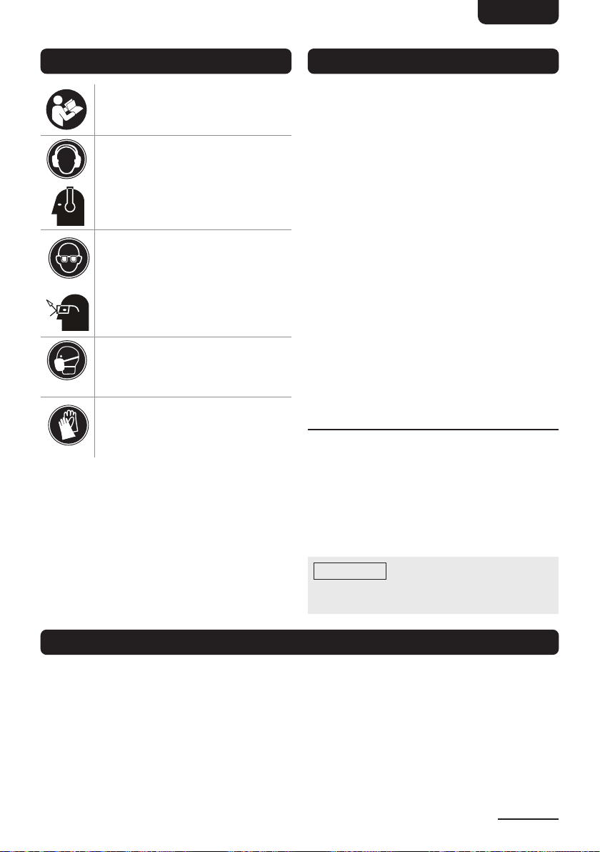
»Always wear impact-resistant eye
protection during operation of the die
grinder or when changing accessories on
the tool� The grade of protection required
should be assessed for each use�
»Ensure that the workpiece is securely
fixed�
»Check regularly that the speed of the die
grinder is not higher than that marked on
it� The speed checks shall be carried out
without the abrasive product mounted
and in accordance with the instructions
given�
»Ensure that sparks and debris resulting
from use do not create a hazard�
»Disconnect the grinder from the energy
supply before changing abrasive product
and servicing�
»The risk to others should also be
assessed while doing this�
1.3 Entanglement hazards
»Chocking, scalping and/or lacerations
can occur if loose clothing, personal
jewelery, neck wear, hair or gloves are not
kept away from the tool and accessories�
1.4 Operating hazard
»Avoid contact with the rotating spindle
and inserted tool to prevent cutting of
hands and other body parts�
»Use of the tool can expose the operators
hands to hazards, including cuts and
abrasions and heat� Wear suitable gloves
to protect hands�
»Operators and maintenance personnel
shall be physically able to handle the
bulk, weight and power of the tool�
»Hold the tool correctly; be ready to
counteract normal or sudden movements
and have both hands available�
»Maintain a balance body position and
secure footing�
»Release the start and stop device in case
of an interruption of the energy supply�
»Use only lubricants recommended in this
user manual�
»Personal protective safety glasses shall
be used; suitable gloves and protective
clothing are recommended�
»A rotary file shall not be operated at a
speed exceeding the rated speed�
»For overhead work, wear a safety helmet�
»Be aware that there is a running-on for
several seconds of the rotary inserted tool
after the start-and-stop device has been
released�
»Do not operate the tool in explosive
atmospheres, such as in the presence
of flammable liquids, gases, or dust� The
abrasives are able to create sparks when
working material, resulting in the ignition
of the flammable dust or fumes�
1.5 Repetitive motion hazards
»When using a die grinder to perform
work-related activities, the operator can
experience discomfort in the hands,
arms, shoulders, neck or other parts of
the body�
»While using a die grinder, the operator
should adopt a comfortable posture
whilst maintaining a secure footing
and avoiding awkward or off balance
postures� The operator should change
posture during extended tasks; this can
help avoid discomfort and fatigue�
»If the operator experiences symptoms
such as persistent or recurring
discomfort, pain, throbbing, aching,
tingling, numbness, burning sensations
or stiffness, these warning signs should
not be ignored� The operator consult a
qualified health professional�

EN
5
1.6 Accessory hazards
»Disconnect the die grinder from the
energy supply before fitting on changing
the inserted tool or accessory�
»Use only sizes and types of accessories
and consumables that are recommended
in this user manual; do not use other
types or sizes of accessories or
consumables�
»Avoid direct contact with the inserted tool
during and after use as it can be hot or
sharp�
»Never mount a grinding wheel, cut-off
wheel or router cutter on a die grinder� A
grinding wheel that bursts can cause very
serious injury or death�
»Do not use mounted wheels which are
chipped or cracked or which could have
been dropped�
»Use only permitted inserted tools of the
correct shaft diameter�
»Pay special attention to the fact that the
permitted speed of the mounted point
has to be lowered due to the increase
of the length of the shaft between the
end of the collet and the mounted point
(overhang)� Make sure that the minimum
gripping length of 0�39" (10 mm) is
observed�
»Be aware of the risk of mismatching the
diameter of the shaft of the mounted
point and that of the collet�
1.7 Workplace hazards
»Slips, trips and falls are major causes
injury when using this tool� Be aware of
slippery surfaces caused by use of the
tool and also of trip hazards caused by
the air line or hydraulic hose�
»Proceed with care in unfamiliar
surroundings� There can be hidden
hazards, such as electricity or other utility
lines�
»The die grinder is not intended for use in
potentially explosive atmospheres and is
not insulated against contact with electric
power�
»Ensure that there are no electrical cables,
gas pipes, etc�, which can cause a
hazard if damaged by use of the tool�
1.8 Dust and fume hazards
»Dust and fumes generated when using
die grinders can cause ill health (for
example cancer, birth defects, asthma
and/or dermatitis); risk assessment and
implementation of appropriate controls
for these hazards are essential�
»Risk assessment should include dust
created by the use of the tool and the
potential for disturbing existing dust�
»Operate and maintain the die grinder as
recommended in this user manual, to
minimize dust or fume emissions�
»Direct the exhaust so as to minimize
disturbance of dust in a dust-filled
environment�
»Where dust or fumes are created, the
priority shall be to control them at the
point of emission�
»All integral features or accessories for
the collection, extraction or suppression
of airborne dust or fumes should
be correctly used and maintained in
accordance with this user manual�
»Select, maintain and replace the
consumable/inserted tool as
recommended in this user manual, to
prevent an unnecessary increase in dust
or fumes�
»Use respiratory protection in accordance
with the employer’s instructions and
as required by occupational health and
safety regulations�
»Working in certain materials creates
emission of dust and fumes, causing a
potentially explosive environment�

EN
6
1.9 Noise hazards
»Exposure to high noise levels can cause
permanent, disabling hearing loss and
other problems, such as tinnitus (ringing,
buzzing, whistling or humming in the
ears)� Therefore, risk assessment and
implementation of appropriate controls
for these hazards are essential�
»Appropriate controls to reduce the risk
may include actions such as damping
materials to prevent work pieces from
“ringing”�
»Use hearing protection in accordance
with the employer’s instructions and
as required by occupational health and
safety regulations�
»Operate and maintain the die grinder as
recommended in this user manual, to
prevent an unnecessary increase in the
noise level�
»Select, maintain and replace the
consumable/inserted tool as
recommended in this user manual, to
prevent an unnecessary increase in noise�
»If the die grinder has a silencer, always
ensure that it is in place and in good
working order when the die grinder is
being operated�
1.10 Vibration and noise reduction
To reduce the impact of noise and vibration
emission, limit the time of operation, use
low-vibration and low-noise operating
modes as well as wear personal protective
equipment(PPE)�
Take the following points into account to
minimize the vibration and noise exposure
risks:
»Select, maintain and replace the
consumable/inserted tool as
recommended in this user manual, to
prevent an unnecessary increase in
vibration and noise levels�
»Use correct attachments for the die
grinder and ensure they are in good
condition�
»Hold the tool with a light but safe grip,
taking account of the required hand
reaction forces, because the risk from
vibration is generally greater when the
grip force is higher�
»Plan work schedule to spread any high
vibration tool use across a longer period
of time�
»Exposure to vibration can cause disabling
damage to the nerves and blood supply
of the hands and arms�
»Wear warm clothing when working in cold
conditions and keep your hands warm
and dry�
»If you experience numbness, tingling,
pain or whitening of the skin in your
fingers or hands, stop using the die
grinder, and consult a physician�
»Support the weight of the tool in a stand,
tensioner or balancer if possible�
»An improperly mounted or damaged
inserted tool can cause excessive
vibration levels�
1.11 Residual risks
Even if you are operating this die grinder in
accordance with all the safety requirements,
potential risks of injury and damage
remain� The following dangers can arise in
connection with the structure and design of
this die grinder:
»Health defects resulting from vibration
emission if the die grinder is used over
long periods of time or not adequately
managed and properly maintained�
»Injuries and damage to property due to
broken application tools or the sudden
impact of hidden objects during use�
»Danger of injury and property damage
caused by flying objects�
»Burns, if touching hot surfaces�

EN
7
1.12 Additional safety for pneumatic
power tools
»Air under pressure can cause severe
injury:
- always shut off air supply, drain hose of
air pressure and disconnect tool from air
supply when not in use, before changing
accessories or when making repairs;
- never direct air at yourself or anyone else�
»Whipping hoses can cause severe injury�
Always check for damaged or loose
hoses and fittings�
»Do not exceed the maximum air pressure
stated on the tool�
»Whenever universal twist couplings (claw
couplings) are used, lock pins shall be
installed and whip check safety cables
shall be used to safeguard against
possible hose-to-tool connection failure�
»Never carry an air tool by the hose�
1.13 Kickback and related warnings
»Kickback is a sudden reaction to a
pinched or snagged rotating wheel,
sanding disc, grinding stone or any other
accessory�
»Pinching or snagging causes rapid
stalling of the rotating accessory which
in turn causes the uncontrolled tool to
be forced in the direction opposite of the
accessory’s rotation�
»Kickback is the result of tool misuse and/
or incorrect operating procedures or
conditions and can be avoided by taking
proper precautions�
»Maintain a firm grip on the tool and
position your body and arm to allow you
to resist kickback forces� The operator
can control kickback forces, if proper
precautions are taken�
»Use special care when working corners,
sharp edges etc� Avoid bouncing and
snagging the accessory� Corners, sharp
edges or bouncing have a tendency to
snag the rotating accessory and cause
loss of control or kickback�
»Do not attach a toothed saw blade� Such
blades create frequent kickback and loss
of control�
»Always feed the bit into the material in
the same direction as the cutting edge
is exiting from the material (which is the
same direction as the chips are thrown)�
Feeding the tool in the wrong direction
causes the cutting edge of the bit to
climb out of the work and pull the tool in
the direction of this feed�
1.14 Safety of grinding tools
»Always try to hold the tool with both
hands during operation�
»Ensure that the workpiece is kept at waist
height where possible� Never use the
tool between the legs whilst sitting on the
floor�
»Ensure that sparks and particles resulting
from use do not create a hazard� Use
screens where appropriate�
»Never bump the grinding stones onto the
workpiece, or let it hit any other objects
while grinding�
»Always allow the tool to run up to full
operating speed before applying it to the
material being worked on�
»Use clamps, or vices to hold the
workpiece� Failure to secure the
workpiece could result in serious personal
injury�
»Do not position your hand in line with and
behind the rotating disc� When the disc,
at the point of operation, is moving away
from your hand, the possible kickback
may propel the spinning wheel and the
tool directly at you�
»Do not restart grinding in the workpiece
until the disc reaches full speed then
carefully re-enter� The disc may bind,
walk up or kickback if the tool is restarted
in the workpiece�

EN
8
1.15 Safety of sanding tools
»Inspect the sanding disc before use� Do
not use if split or broken�
»Avoid any contact with a moving sanding
disc and always wear gloves when
possible to protect the hands�
»Beware of potentially explosive
atmospheres being caused by dust /
fumes resulting from sanding and used
dust extraction systems where possible�
»Always wear a face mask when using
the sander as protection from airborne
particles of sanded material�
»Avoid disturbing existing dust and
minimize the scattering of dust in the
workplace environment�
»Take steps to control the dust at the point
of emission�
1.16 Emergency
Familiarize yourself with the use of this
die grinder by means of this user manual�
Memorize the safety directions and follow
them to the letter� This will help to prevent
risks and hazards�
»Always be alert when using this die
grinder, so that you can recognize and
handle risks early� Fast intervention can
prevent serious injury and damage to
property�
»Immediately release the air tool handle
and disconnect the air supply if there are
malfunctions� Have the tool checked by
a qualified professional and repaired, if
necessary, before you operate it again�
WARNING
»Some dust created by power sanding,
sawing, grinding, drilling, and other
construction activities, contain
chemicals known (to the State of
California) to cause cancer, birth
defects or other reproductive harm�
Some examples of these chemicals
are: lead from lead-based paints,
crystalline silica from bricks and
cement or other masonry products,
arsenic and chromium from chemically
treated lumber� Your risk from these
exposures varies, depending on
how often you do this type of work�
To reduce your exposure to these
chemicals: work in a well ventilated
area, and work with approved safety
equipment, such as those dust masks
that are specially designed to filter out
microscopic particles�
SAVE THESE
INSTRUCTIONS

EN
9
2. Symbols Explanation
Read this user manual carefully
before use�
Wear ear protection,
compliantto:
ANSI/ASA S12�6
Wear eye protection,
compliantto:
ANSI Z87�1
Wear dust protection,
compliantto:
NIOSH (42 CFR 84)
Wear protective gloves,
compliant to:
ANSI/ISEA 105
3. Intended Use
»This pneumatic tool is intended for use in
household and light industrial locations�
It can only be used by skilled, trained
professionals in accordance with the
instructions in this user manual�
»This pneumatic tool is designed to be
used with a sanding disc or other shaft
mounted abrasive tool for sanding
metals, wood, stone, plastics and other
materials� It should only be used for
such sanding applications and within
its marked capacity and ratings� Only
accessories specifically recommended
in this user manual should be used with
this tool� Use in any other manner or with
other accessories could lead to unsafe
operating conditions�
»No liability will be accepted for damages
resulting from improper use or non-
compliance with these instructions�
3.1 Performance
»Factors outside the tool may effect
its operation and efficiency such as
reduced compressor output, excessive
air demand from the air line, moisture
or restrictions in the air line, or the use
of connectors of improper size or poor
condition which will reduce air supply�
NOTICE
Light industrial applications
must follow Occupational Safety and
Health Administration requirements�
4. Air System Requirements
»Use only clean, dry, regulated
compressed air as a power source�
»Air compressors used to drive this tool
must comply with the applicable laws and
regulations�
»A build-up of moisture or oil in the
air compressor will accelerate wear
and corrosion in the tool� Ensure any
moisture is drained from the compressor
daily and the inlet filter is kept clean�
Thoroughly read the user manual of the
air compressor or other power source�

EN
10
»If an unusually long air hose is required,
(26�2 ft / over 8 meters), the air pressure
or the hose inside diameter may need to
be increased�
»The air hose must be rated at least 150%
of the maximum operating pressure of
the tool�
»A typical air line layout is shown in
chapter 4�1� If an automatic lubricator
is used, it will keep the tool in good
condition, but should be regularly
checked and topped up with oil�
»SAE 10 oil should be used and the
lubricator adjusted to approximately
2drops per minute�
»Do not exceed the maximum pressure
for the tool of 90 PSI (6�2 bar)� Higher
pressures and contaminated air will
shorten the life of the tool due to faster
wear and is a possible safety hazard�
»Change filters on the air system on a
regular basis�
4.1 Air line layout diagram
Air Tool Hose Lubricator
Regulator
Filter Shut-off Valve
Drain
Compressor
Drain
Air Dryer
Auto drain

EN
11
5. Product Description
DA B C E F
J
OP
Q
R
S
T
U
V
W
G
NM
L
I
H
K
ARed sanding disc (medium) MAir inlet
BGreen sanding disc (fine) NTrigger lever with safety latch
CBrown sanding disc (coarse) O5x Grinding stones Ø 1/4" (6 mm)
DFine sanding disc (120 grit) P5x Grinding stones Ø 1/8" (3 mm)
EFine sanding disc (60 grit) Q2x Collets (1x pre-assembled)
F3" (7�6 cm) disc holder RMale quick-connector
GCollet nut S2x Wrenches 7/16" / 21/32"
(11 mm / 17 mm)
HSpindle TOil bottle
ILubricating nipple U2" (50 mm) disc holder
JAir tool V2x 1/4" (6 mm) shank
KExhaust W5x 2" (50 mm) sanding discs
LAir regulator wheel (speeds 1 - 4)

EN
12
6. Before First Use
DANGER Risk of suffocation!
»Keep any packaging materials away
from children – these materials
are a potential source of danger,
e�g� suffocation�
»Check the tool for transport damages�
»Remove all the packing materials�
7. Preparing For Use
WARNING Risk of injury!
»Compressed air can be dangerous�
Ensure that you are familiar with all
precautions relating to the use of air
compressors and compressed air
supplies before using the tool�
7.1 Connecting an air hose
WARNING Risk of injury!
»Before performing any assembly and/or
adjustment procedures, make sure the
air hose (not included) is disconnected
from the air inlet (M)�
1� Remove the protective cap covering the
air inlet (M)� Store the protective cap in a
safe place�
M
2� If an automatic lubricator is not being
used, add 2-3 drops of air tool oil (not
included) every two to three hours of use
into the air inlet (M)�
M
T
3� Blow out air line to remove any dirt or
moisture, then connect a flexible air hose
(not provided) to the air inlet (M)� For
hoses equipped with a quick-connector,
use male quick-connector (R)�
R
Flexible air hose

EN
13
NOTICE
Use thread sealant tape (not
included) on the male quick-connector(R)
and/or the air hose and tighten it with
a wrench (not included) for airtight
connection� Do not over tighten�
4� Connect the other end of the air hose to
the air compressor� Set air pressure to
90PSI (6�2 bar)�
7.2 Installing and removing the collet
1� Unscrew and remove the collet nut (G)�
Use the two wrenches (S) to loosen the
collet nut (G) if necessary�
Small wrench
Large wrench
G
2� Pull out the collet (Q) from the spindle (H)�
The collet (Q) can be difficult to remove
once inserted� Use a set of pliers to
loosen the collet (Q) for removal�
Q
Spindle
3� Insert the new collet and screw the collet
nut (G) loosely back on by hand�
Q
G
NOTICE
Two collets of different sizes
are provided� Install the collet that fits the
shank of the grinding stone (O or P) to be
used�
7.3 Installing the grinding stone
WARNING Risk of serious injury!
»Do not use chipped or cracked
grinding stones as they can break off
during operation and cause serious
injury�
1� Once the correct collet size has been
installed, insert the shank of the chosen
grinding stone (O/P) into the collet and
tighten the collet nut (G) by hand�

EN
14
A minimum length of 0�39" (10 mm) of the
shaft must be inside the collet nut for safe
operation�
G
0�39" (10 mm)
O/P
2� Place the small wrench on the spindle(H)
to stop it from rotating and hold it in
place�
3� Use the large wrench to fully tighten the
collet and grip the stone in position by
turning it clockwise until secure�
Large wrench
Small wrench
7.4 Installing the sanding disc
1� Refer to chapter ‘Installing and removing
the collet to install the larger collet and
then insert the shank (V) into the collet�
2� Place the smaller wrench on the spindle
(H) to stop it from rotating�
3� Use the larger wrench to fully tighten the
collet and grip the shank (V) in position�
4� Screw the disc holder (F/U) onto the
shank (V)�
5� Tighten the nut on the shank (V) against
the disc holder (F/U) using the small
wrench�
F/U
V
6� Screw the chosen sanding disc onto the
disc holder (F/U)�
Sanding disc
F/U
7.5 Operating the tool
CAUTION Risk of injury!
»The air tool will continue to rotate for
a short time after the trigger has been
released�
»Do not put the tool down until the
accessory have stopped rotating�

EN
15
NOTICE
»Tool speed can be adjusted by
increasing or decreasing the pressure
on the trigger or by adjusting the air
regulator wheel (L) until the you reach
the desired speed�
»Do not use excess pressure while using
the grinding stone as this will shorten
its life�
1� Use your index finger to slide the safety
latch forward while squeezing the
trigger(N)�
Locking lever
Trigger
2� Release the trigger to stop the air tool�
7.6 Disconnecting the air hose
NOTICE
Do not disconnect the air
supply hose until the compressor has
been shut down and the compressed air
released�
1� Refer to the compressor instruction
manual for the procedure to shut down
and release the compressed air�
2� Once the pressure has been released,
disconnect the air supply hose from the
air inlet (M)�
8. Sanding and Grinding Tips
»Do not force the sanding disc or stone
against the material being worked on�
»The key to efficient grinding is to control
the pressure and surface contact
between the grinding tool and the
workpiece�
»Allow the tool to reach full speed before
working on a workpiece�
»Avoid overloading the grinder� If it
becomes hot during use, rest for a few
minutes while it cools down�

EN
16
9. Troubleshooting
Problem Possible cause Solution
Tool does not start� »Shut-off valve
closed or
obstructed�
»Dirt or gum deposits
on components�
»Throttle lever
malfunction�
»Bearing(s) worn�
»Open the valve� Clean any
obstructions�
»Flush tool with gum solvent� If
problem persists, disassemble,
clean and lubricate internal parts�
»Clean throttle lever mechanism to
ensure free movement� Replace
mechanism if needed�
»Disassemble and inspect bearing�
Grease or replace as needed�
Excessive or abnormal
vibration�
»
Improper lubrication�
»Bearing(s) worn�
»Drip a few drops of air tool oil into
the air inlet to lubricate the moving
parts�
»Disassemble and inspect bearing�
Grease or replace as needed�
Excessive heat
develops in tool�
»
Improper lubrication�
»Drip a few drops of air tool oil into
the air inlet to lubricate the moving
parts�
»After extensive use, apply a shot
of general purpose grease using
a suitable grease gun in the
lubricating nipple (I)�
Tool runs at normal
speed but slows down
under any load�
»Excessive pressure
on tool�
»Worn components�
»
Improper lubrication�
»Reduce the force applied to the
tool�
»Contact a professional repair center�
»Drip a few drops of air tool oil into
the air inlet to lubricate the moving
parts�
Tool does not run�
Air flows freely from
exhaust�
»Motor vanes stuck
due to buildup of
dirt or gum�
»Disconnect air supply and rotate
tool assembly manually�
»Try operating tool in short bursts�
»Drip a few drops of air tool oil into
the air inlet to lubricate the moving
parts�
Tool starts immediately
as soon air supply is
connected without
lever being pressed�
»Throttle valve
cap and O-rings
damaged�
»Shut of air supply and stop using
the tool� Inspect/repair the throttle
valve cap� If in doubt, contact a
professional repair center�

EN
17
Problem Possible cause Solution
Tool runs slowly� Low
air pressure�
»Motor parts jammed
with dirt or gum
deposits
»General airflow
blocked by dirt�
»Moisture or
obstruction in air
hose�
»Regulator set to low
pressure�
»Improper size of air
transmission lines,
hoses, fittings, or
quick-connectors�
»Examine air filter on the compressor
and air inlet strainer for cleanliness�
»Operate the tool in short bursts�
»Air supply must be clean and dry�
Clean out air hose(s) and remove
any kinks or bends�
»Adjust the pressure at the regulator
to max� 90 PSI (6�2 bar)� Check
for loose connections at air inlet,
o-rings, etc�
»Use appropriate-sized air lines/
hoses� Verify proper fittings/quick-
connectors�
10. Cleaning and Maintenance
WARNING Risk of injury!
»Make sure that the air tool is
disconnected from the air supply
before starting any cleaning or
maintenance procedures�
10.1 Cleaning
»Keep the body of the tool clean and free
from excessive oil and debris by wiping
with a cotton rag�
»Grit or gum deposits inside the tool may
also reduce its efficiency� This condition
can be corrected by cleaning out the air
strainer and flushing out the tool with
gum solvent or oil�
Strainer
»Never use corrosive detergents, wire
brushes, abrasive scourers, metal or
sharp utensils to clean the tool�
»Check the air inlet strainer frequently for
blockage and clean if necessary�
10.2 Maintenance
WARNING
»This air tool should be inspected
periodically to make sure it is in a safe
working condition�
Regular maintenance ensures the air tool
operates in a safe and working condition�
10.2.1. Daily maintenance
»Drain water from the air tank, air line and
compressor before each use of the air
tool�
»Pour a few drops of air line oil into the
air inlet� This should be carried out
regardless of whether or not an in-line
lubricator is used�
»If an in-line lubricator is not used, this
procedure should be repeated after every
two to three hours of use�

EN
18
10.2.2. Weekly maintenance
»Check the air inlet (M) strainer for
blockage and clean if necessary�
»Check the oil level at in-line lubricator (if
used)�
»Check the speed and vibration levels
regularly and after each service�
10.3 Greasing
The air tool is fitted with a lubricating nipple(I)
to provide a facility for lubrication of the drive
gears� After extensive use, apply a shot of
general purpose grease using a suitable
grease gun�
I
10.4 Storage
»When not in use, disconnect from air
supply, clean the air tool and store in a
cool and dry place away from children
and pets�
»Always store the product in the carry
case provided�
»For long term storage or if the air tool is
idle for longer than 24 hours, run a few
drops of air line oil into the air inlet (M),
and run the tool for 5 seconds in order to
lubricate the internal parts�
»Once the air hose is disconnected, cover
the air inlet (M) with the protective cap�
»Do not store the tool in environments
where temperature is below 32 °F (0 °C)�
10.5 Service
»Have the air tool serviced by a qualified
repair person using only identical
replacement parts� This will ensure that
the safety of the die grinder is maintained�
»When servicing the air tool, use only
identical replacement parts� Use of
unauthorized parts or failure to follow
maintenance instructions may create a
risk of injury�
10.6 Disposal
Protect yourself and the environment�
This tool contains materials which can be
recovered or recycled� When its useful life
has expired, return the tool to a specialized
recycling facility�
11. Feedback and Help
Love it? Hate it? Let us know with a
customer review�
AmazonBasics is committed to delivering
customer-driven products that live up to your
high standards� We encourage you to write
a review sharing your experiences with the
product�
amazon.com/review/
review‑your‑purchases#
amazon.com/gp/help/customer/
contact‑us
— or —
Contact Customer Service at
+1 877‑485‑0385

EN
19
12. Specifications
Model number AT-7034MSK
Air inlet 1/4" (female)
Minimum hose size (I�D) 3/8"
Rated (maximum) air pressure 90 PSI (6�2 bar)
Average air consumption 4 CFM (28�3 LPM)
Rated speed (at no load) 20,000 (±10%) RPM @ 90 PSI (6�2 bar)
Net weight (tool only) approx� 1�33 lbs (0�6 kg)
Dimensions (W x H x D) approx� 6�1 x 1�4 x 2�9" (15�5 x 3�8 x 7�4cm)
Noise emission level
Sound pressure level (LpA): 76�9 dB(A)
Sound power level (LwA): 87�9 dB(A)
Uncertainty KwA: 3 dB(A)
NOTICE
The noise emission values have been
determined according to noise test code given in
ISO15744� Wear hearing protection, especially when
sound pressure is over 80 dB(A)�
Vibration emission levels
Hand-arm vibration ahw: <2�9 m/s²
Uncertainty K= ±1,5 m/s
NOTICE
The declared vibration value has been
measured in accordance with a standard test method
(according to ISO 28927-12) and may be used for
comparing one tool with another� The declared vibration
value may also be used to evaluate the exposure for the
user caused by vibration in advance�
CAUTION Risk of injury!
»Depending on the actual use of the tool the vibration values can differ from the
declared total values� Adopt proper measures to protect yourself against vibration
exposures� Take the whole work process including times the tool is running under no
load or switched off into consideration! Proper measures include among others regular
maintenance and care of the tool and accessories, keeping hands warm, periodical
breaks and proper planning of work processes�

EN
20
13. Parts List
No. Description No. Description
1 Housing 25 Bearing
2 Trigger 26 Rear plate
3 Lever 27 Pin
4 Spring 28 Rotor
5 Pin 29 Rotor blade
6 Trigger pin 30 Cylinder
7 O-ring 31 Rotor collar
8 O-ring 32 Front plate
9 Valve stem 33 Pin
10 Spring 34 Bearing
11 O-ring 35 Angle gear
12 Valve plug 36 Clamp nut
13 Soft grip 37 Cap
14 Rear cover 38 Angle head
15 O-ring 39 Grease cap
16 Set plate 40 Bearing
17 O-ring 41 Gear
18 Air regulator 42 Lock nut
19 O-ring 43 Work spindle
20 Air inlet 44 Semi-round key
21 Lock pin 45 Collet
22 Spring 46 Collet jacket
23 Front cover 47 Wrench (small)
24 Gasket 48 Wrench (large)
Table of contents
Languages: