2
Document Index.
1 Installation Requirements
1.1 Health & Safety
1.2 Model definitions
1.3 Technical Details
2 Commissioning Instructions
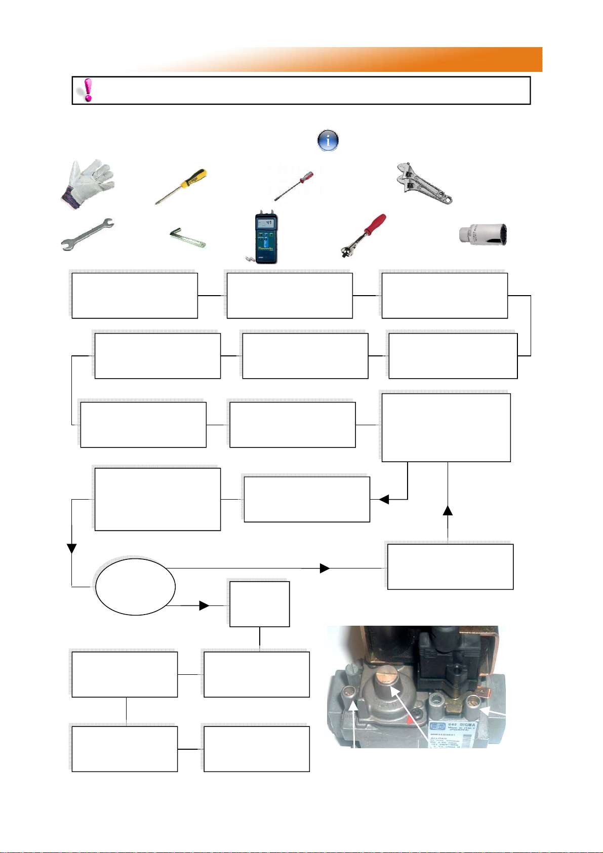
3.1 Tools Required
3.2 Commissioning Chart
3 Servicing Instructions
3.1 Tools required
3.2 Burner Description
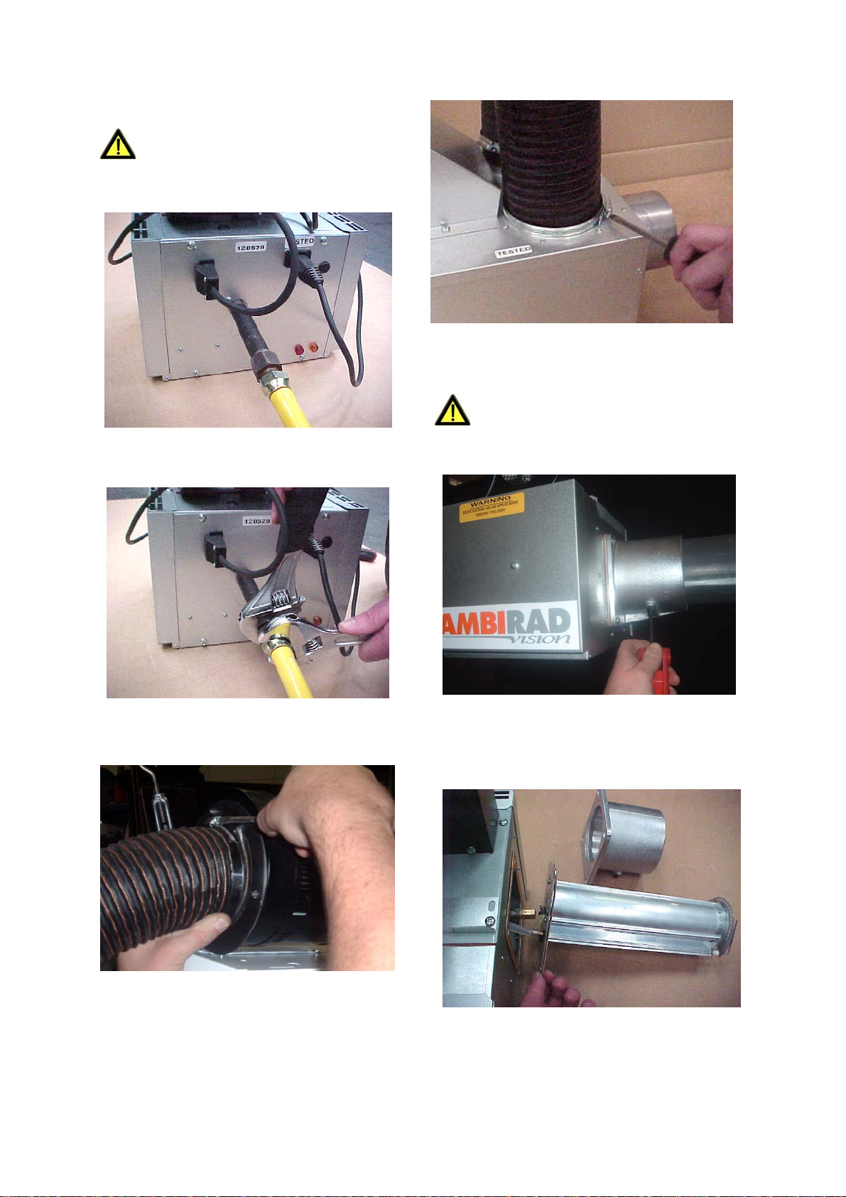
3.3 Burner Removal
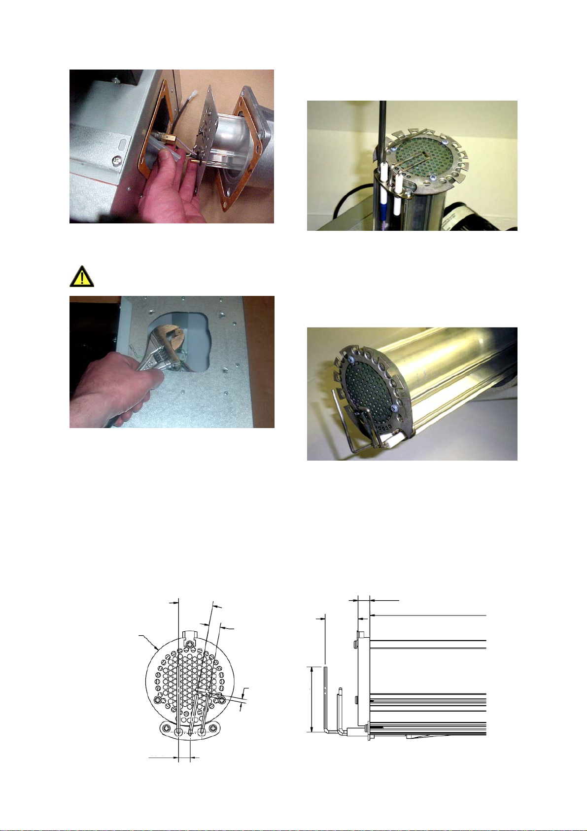
3.4 Burner Gas Injector Servicing
3.5 Burner Head and Electrode Servicing
3.6 Combustion Fan Assembly
3.7 Radiant Tube Servicing
3.8 Heat Exchanger Servicing
Introduction. and attention is required to ensure that working
at height regulations are adhered to at the
mounting heights specified.
PLEASE READ this document prior to
installation to familiarise yourself with the
components and tools you require at the various
stages of assembly.
All Dimensions shown are in mm unless
otherwise stated.
The manufacturer reserves the right to alter
specifications without prior notice.
Welcome to the new range of high efficiency
AmbiRad Vision radiant tube heaters. Local
regulations may vary in the country of use and
it is the installers responsibility to ensure that
such regulations are satisfied.
All installation, assembly, commissioning and
service procedures must be carried out by
suitable qualified competent persons
appropriate to the statutory regulations in the
country of use.
When assembling, installing, commissioning
and servicing is undertaken on radiant tube
heaters specified in these instructions, due care
3.9 Reflector Servicing
3.10 Inspection of Flue
3.11 Re-commissioning after Service
4 Spare Parts
5 Fault Finding Guide
6 Replacing Parts
6.1 Burner Controller Replacement
6.2 Air Pressure Switch Replacement
6.3 Gas Valve Replacement
7 User and Operating Instructions
7.1 To Start Heater
7.2 To Switch off Heater
7.3 Routine Maintenance Between Service Intervals
7.4 Frequency of Servicing
1. Installation Requirements.
Isolate any electrical supply to the
heater and controller before proceeding.
relevant British Standards and Codes of
Practice by a qualified installer. Isolate all
electrical supplies to the heater & controller
before proceeding.
For your own safety we recommend the use of
safety boots and leather faced gloves when
handling sharp or heavy items. The use of pro-
tective eye wear is also recommended.
1.2 Model Definitions
VSXUT = Ambirad Vision High efficiency U
Tube heater with painted powered burner, deep
profile stainless steel reflector and end caps,
reflector canopy and end caps in Aluzink
1.1 Health and Safety
AmbiRad heaters must be installed in
accordance with the relevant provisions of the
Gas Safety (Installations and Use) Regulations
1998. Due account should also be taken of any
obligations arising from the Health and Safety
at Works Act 1974 or relevant codes of prac-
tice. In addition the installation must be carried
out in accordance with the current IEE wiring
regulations (BS 7671:2001), BS 6896:2005
(Industrial & Commercial) and any other