2. Troubleshooting
Fault
Head correctly hyperextended, but
insufflation not possible.
Head correctly hyperextended, but
after a few insufflations, air can no
longer be insufflated.
Indication of stomach inflation
despite correct volume and pressure
insufflation.
No indication of stomach inflation
despite high volume and pressure
inflation.
No insufflation, but constant indica-
tion of stomach inflation.
Hand position correct, but fault
signalled.
Hand position incorrect, but fault not
signalled.
Wrong indication for insufflation
volume.
Wrong indication for depth of com-
pression.
Head loose.
Possible cause
Head chain or nylon tie broken.
Defective elastic net.
Substantial leakage in system.
Defective stomach valve.
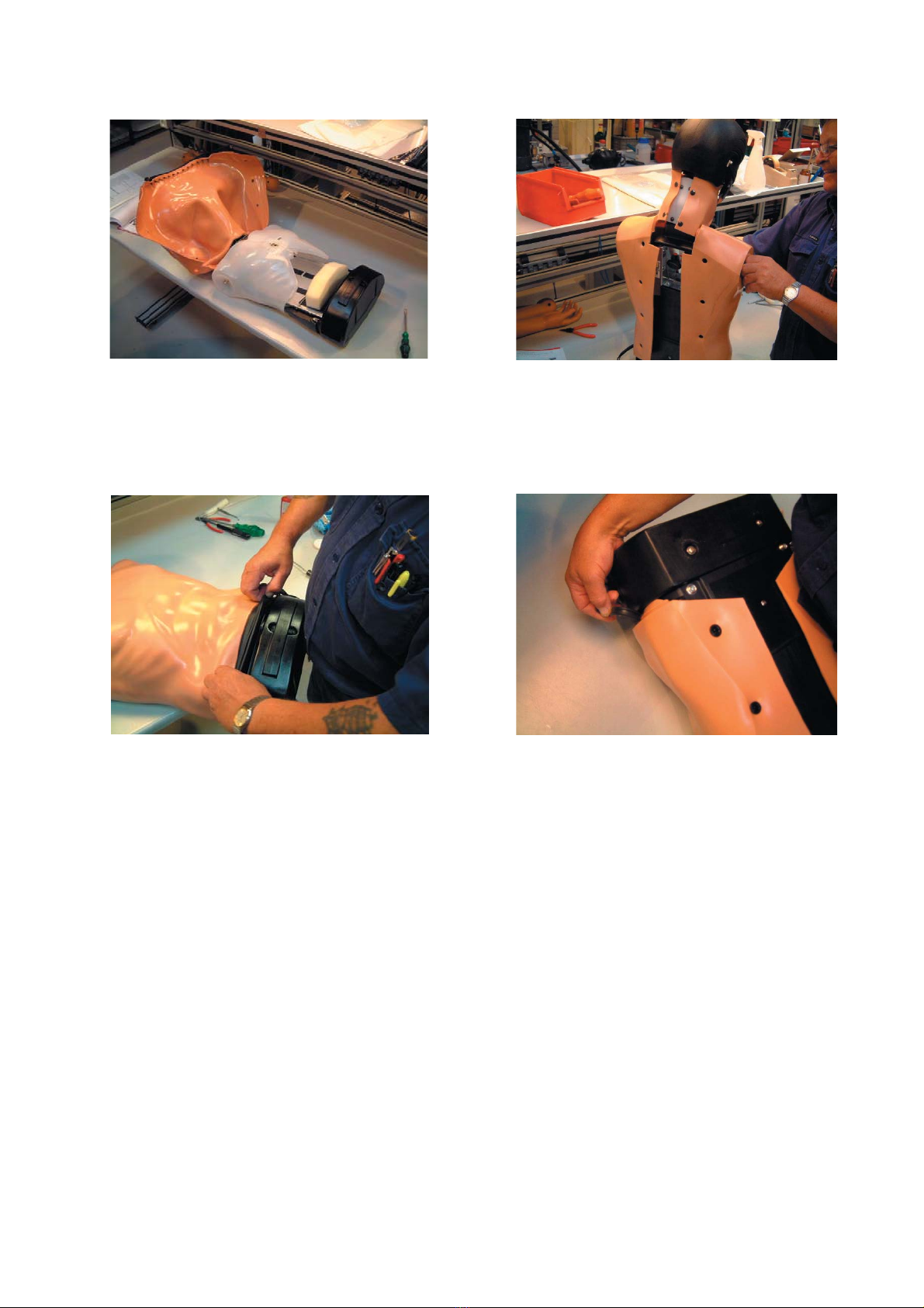
Black plate over stomach bag not
coupled to instrument.
Black plate over stomach bag not
coupled to instrument.
Thrust roller or thrust roller holder
at pressure point defective or miss-
ing.
Missing or defective spring at thrust
roller
Instrument wrongly adjusted.
Instrument wrongly adjusted.
Loose screws and nuts at head
mounting.
Parts have separated.
Remedy
Replace with nylon tie.
Replace elastic net.
Check out system between head
and lung/stomach bags, including
stomach valve. Replace the defec-
tive parts.
Replace stomach valve.
Couple black plate correctly to
instrument.
Couple black plate correctly to
instrument
Replace thrust roller and thrust
roller holder
Replace spring.
Adjust instrument (see section 8)
Adjust instrument (see section 8)
Insert screw and nut and then
secure using a lock nut.
Page 4