SPW-10
until the plate is finished heating the profiles and is returned to the rest position. If one
of the two keys, or both, are released before the end of welding, the cycle will be
interrupted and the welding machine will return to the rest position. This allows the
operator to interrupt the cycle in case of error or emergency.
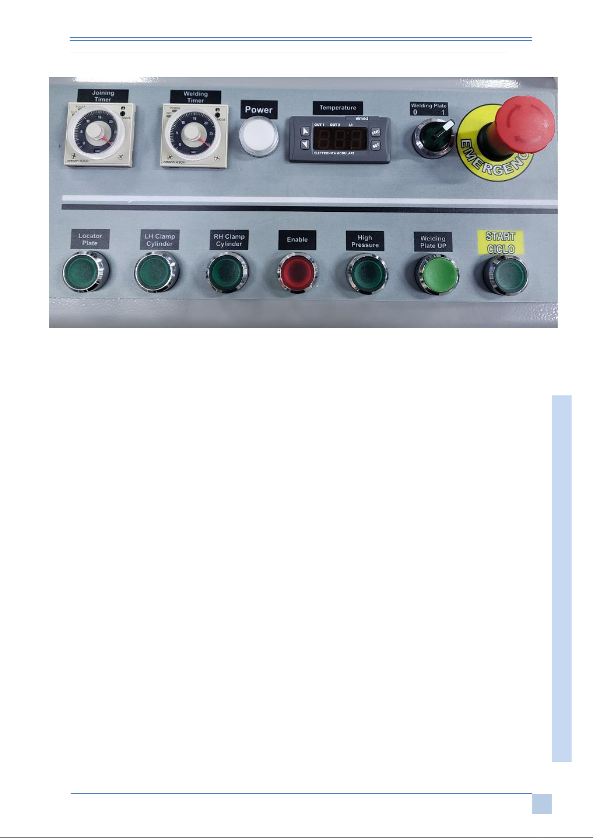
Press the button Welding Plate
to change the temperature. Before this operation, make
sure you have switched off the heating elements and that the plate has cooled completely.
- Adjusting temperature setting on controller; press SET and change it to ON.
doing this you will be able to freely change the temperature pressing the up and down arrows.
4WARNINGS
Welding reduces the length of profiles from 3 to 5 mm. Make of test samples and determine
whether you need to cut longer profiles.
Pay close attention to the installation of counterblocks; their correct placement is one of the
factors that most affects the welding result. The manufacturer does not provide
counterblocks but can provide a set of counterblocks connections.
Do not weld profiles when the ambient temperature is below 18-20°C.
Make sure the cloth that covers the heating plate is intact and clean; replace it if damaged.
The heating plate temperature must be constant over the entire surface; check it periodically
with a precision thermometer, making sure that the measured temperature matches the one
set.
The accuracy of cutting angles of the profiles to be welded is extremely important; imprecise
cuts will affect the welding result.
For all non-coated profiles, the weld seam is 2 mm; this value ensures the best welding
sealing;
For coated profiles, the weld seam is 0.2 mm; this reduces the curb line of the subsequent
cleaning.
Carry out tests to determine the different welding parameters; set the temperature controller
of the heating plate at 240°C and perform a welding cycle. After reviewing the result, raise
the temperature if the profile shows little resistance during the burst test. Lower the
temperature if the weld curb begins to turn yellowed.
5NORMAL SHUT-DOWN
Is activated by the Stop button on the general panel; stops the machine.