American Landmaster 18931-R User manual

19148 Winch Installation Guide Rev A
Page 1of 10
18931-R 2500 Lb. Winch with Nylon Rope
19148 –Winch Installation Guide
SPECIAL REQUIREMENTS: Used on both Standard Cab & Crew Cab
TOOLS REQUIRED
ESTIMATED INSTALL
TIME
RECOMMENDED SKILL
LEVEL
Philips Screw Driver
General Purpose Pliers
2 Hours
Intermediate
½” Socket & Ratchet
Wire Cutters
½” Wrench
9/16” Wrench
4 mm Allen Wrench
9/16” Socket & Ratchet
7/16” Wrench
7/16” Socket & Ratchet
3/8” Socket & Ratchet
Before you begin, check the contents of the kit against the parts list below. Immediately contact American Landmaster with any questions or
discrepancies. American Landmaster cannot assume responsibility for any damage or injury resulting from incorrect installation of parts. American
Landmaster suggests that accessory kits be installed by an authorized American Landmaster dealer or service center.
!! WARNING !!
Serious Injury or death could occur!
• Use proper personal protective equipment during installation of this kit. Use safety glasses.
(1) Winch with Nylon Rope (1) Winch Harness (1) Contactor with cables (1) Winch Bumper Bracket & Bolts
(1) Winch Switch (2) Winch Mounting bolts (12) Tie Wraps (3) Christmas Tree Tie Wraps
(1) Remote Winch Connector Cap (4) Remote Connector Mounting Screws #6 (4) Remote Connector Lock Nuts #6
(1) Remote Winch Switch (4) 1.5” by ¼” Contactor Mounting Bolts (4) 1/4” Contactor Lock Nuts
Fig 1 –Kit contents –2500 Pound Winch
PARTS LIST FOR AMERICAN LANDMASTER ACCESSORY KIT

19148 Winch Installation Guide Rev A
Page 2of 10
ASSEMBLY INSTRUCTIONS:
Instructional video: In Process
Preliminary Dis-assembly instructions:
1- Remove windshield, if equipped.
2- Remove the hood. Remove three screws from each front fender and two screws from the front hood. Lift the hood off
and set aside. If the vehicle has turn signals, disconnect the amber lights by depressing the release tab on each turn
signal lamp connector and pull apart. Do not separate by pulling on the wires. Set the hood aside where it will not be
damaged.
Figure 2: Removing Three Fender Fasteners Figure 3: Removing Two Hood Fasteners
3- Remove the Black Instrument panel cover. Unscrew each stainless steel fasteners that holds down the black instrument
panel cover using a 4 millimeter Allen wrench. Place the fasteners in a small container so they do not get lost. Lift the
cover straight up and off the panel. Set the cover aside where it will not get damaged.
Figure 4: Removing Black Instrument Panel Cover
Black Instrument
Panel cover

19148 Winch Installation Guide Rev A
Page 3of 10
Figure 5: Remove Battery from Vehicle
4- Ensure that the ignition key is OFF.
5- Remove the negative battery cable first using a ½” socket and wrench. Fold cables back out of the way.
6- Remove the positive battery cables. Fold cables back out of the way.
7- Remove the battery hold down bracket by removing the two hold down bolts using a using a ½” socket and wrench. Save
all bolts and nuts in a small container so that they do not get lost.
8- Remove the battery and store in a safe place.

19148 Winch Installation Guide Rev A
Page 4of 10
Winch System Layout:
The following diagram provides a high level view of the major components of the winch system. Get familiar with the system
layout and connections.
1. The gray 4 pin Winch harness connector connects to the gray 4 pin connector on the main instrument panel harness.
2. The white contactor connector mates with the white winch harness connector.
3. The circular 3 pin connector is mounted to the silver dash panel.
4. The red and black winch power cables are connected to the jump start stud.
5. The yellow and green winch motor cables attach to the winch motor.
Follow the instructions carefully as shown below. A step by step installation process is listed in detail.

19148 Winch Installation Guide Rev A
Page 5of 10
Winch Motor Installation:
1- Remove the existing frame bracket from the front of the vehicle by removing the two existing 5/16” bolts using a 9/16”
wrench and socket.
2- Install the winch with mounting plate onto the front frame as shown below.
Figure 6: Remove Existing Bracket. Figure 7: Mount Winch on Frame with 4 Bolts
3- Fasten the winch to the frame by re-using the two bolts that were removed plus the two additional 5/16” bolts provided
in the kit. Re-use the original bracket attachment points plus the two points on the front frame.
Winch Contactor Installation:
1- Locate the power contactor from the kit.
2- The power and winch cables will already be attached to the winch contactor.
3- Mount the contactor and cables up to the rear ledge on the back side of the instrument panel frame on the passenger
side. The red cable should be located closest to the dash panel. Make sure the red cable is not rubbing on any metal
surfaces.
Remove
Driver Side
Rear of Vehicle

19148 Winch Installation Guide Rev A
Page 6of 10
Figure 8: Winch Contactor Mounting Location
4- Use the four 1.5” by ¼” bolts and lock nuts provided in the kit to secure the contactor to the instrument panel.
5- Route the black and red cables to the jump start stud to the left of the contactor. Remove the stud bolts with a ½” socket
and attach the red cable to the other red cables as the positive feed. Attach the black cable to the other black cables as
the negative feed.
6- Re-tighten the jump start stud bolts using a 1/2” socket wrench. Ensure that all of the red positive battery cables are
oriented in such a manner that they are NOT rubbing or in contact with the frame of the instrument panel structure.
7- Secure the red and black cables to the instrument panel frame with two regular tie wraps on the pipe structure.
8- Position the yellow and black cables on the passenger side frame tube to the winch motor. Use Christmas tree tie wraps
and insert 3 of these tie wraps into the holes provided on the frame.
9- Secure the green and yellow cables with these tie wraps.
10-Attach the yellow cable to the winch motor bolt that is to the front of the vehicle using a 3/8” socket.
11-Attach the green cable to the winch motor bolt that is to the rear of the vehicle using a 3/8” socket.
12-DO NOT OVERTIGHTEN.
13-Cut off the excess length of the tie wraps with a wire cutter. See picture below.

19148 Winch Installation Guide Rev A
Page 7of 10
Figure 9: Cables Routed to the Winch Motor Figure 10: Proper Cable attachment to the Winch Motor
Winch Switch Installation:
1- Choose and open spot on the seven switch panel to mount the winch switch.
2- Push the switch blank out from the rear.
3- Insert the winch switch from the front until it snaps into positon.
Figure 11: Winch switch Installation
Winch Harness Installation:
1- Locate the wire harness from the kit.
2- Lay the winch harness in the rear of the instrument panel.
3- Locate the left most gray 4 pin connector as shown below.
4- Remove the connector cap by depressing and holding it depressed to remove it from the instrument panel harness. DO
NOT REMOVE THE CAP BY PULLING ON THE WIRES. Only pull apart by holding onto the connector.
Front of Vehicle

19148 Winch Installation Guide Rev A
Page 8of 10
Figure 12: Winch Connector on Instrument Panel Harness
5- Connect the four pin connector of the winch harness to the open connector on the instrument panel harness.
6. Remove the rubber plug from the right most hole on the instrument panel.
Figure 13: Remote Winch Plug Figure 14: Remote Winch Switch Connector Orientation
7. Place the gray three pin connector through this hole with the connector oriented as shown in the picture.
8. Use the four #6 screws and nuts to attach this connector to the instrument panel face.
9. Use a Philips screwdriver to start threading the screws into the connector. This will hold the connector in place on the
dash panel. Push the connector toward the dash panel from behind with one hand during this step.
10. Start the nuts on the back side to fully secure the connector.
11. Use a Philips screw driver on the front and a pliers on the back to complete the fastening of the connector.
12. Install the gray cap with a quarter turn when you are not using the remote winch switch.
Winch Connector
Remove
Receptacle with No Notch on Top
Notch
h
Remove
Notch
h
Remove

19148 Winch Installation Guide Rev A
Page 9of 10
Figure 15: Remote Winch Capped Off Figure 16: Remote Winch Switch hooked up
13. Connect the white two pin connector of the winch harness to the winch contactor two pin white connector.
Figure 17: Connecting the Contactor to the Winch Harness
14. Attach the winch harness switch connector to the winch switch in the dash.
15. Locate the black ten pin connector on the winch harness and route it up to the rear of the seven switch panel.
16. Be sure to install the switch harness connector in the correct orientation. Line up the hook on the switch with the latch
on the harness connector. The hook is on the bottom side of the switch. Place one hand on the front of the switch while
installing the harness connector on the rear. A rocking motion will make installing the harness connector easier. Ensure
that the connector is lined up with the switch and do not bend the switch pins. Do not force the connection. Push the
harness connector onto the switch until the two meet with no gap between them.

19148 Winch Installation Guide Rev A
Page 10 of 10
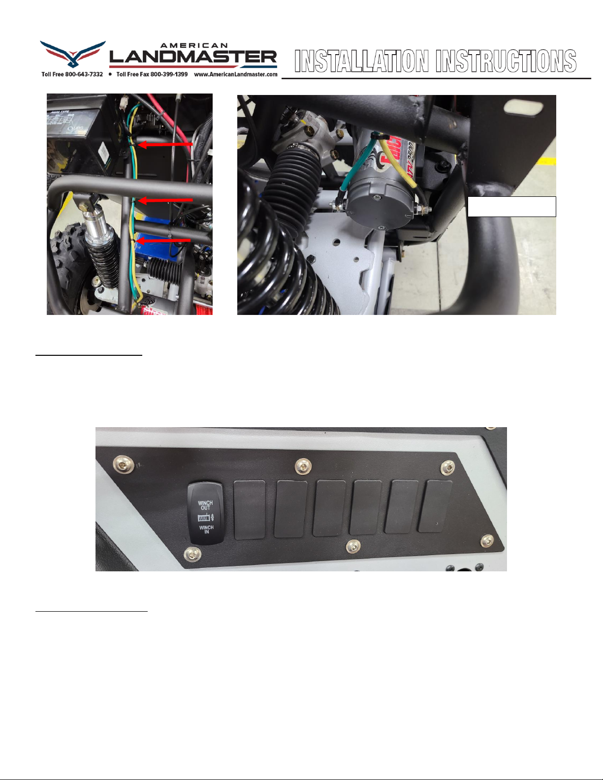
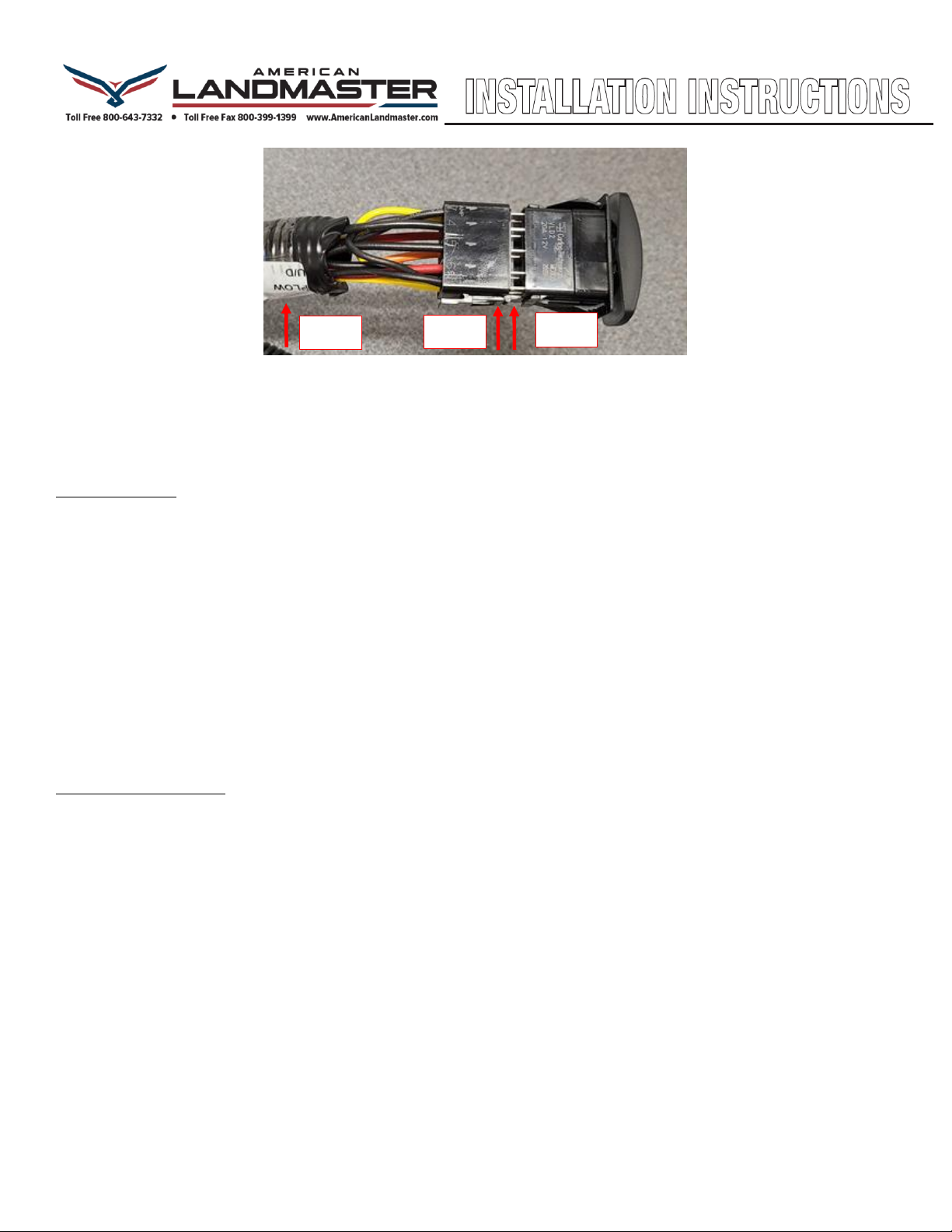
Figure 14: Ensuring Switch Orientation with the Harness Connector
17. Trim off the tie wrap tails at all locations with wire cutters.
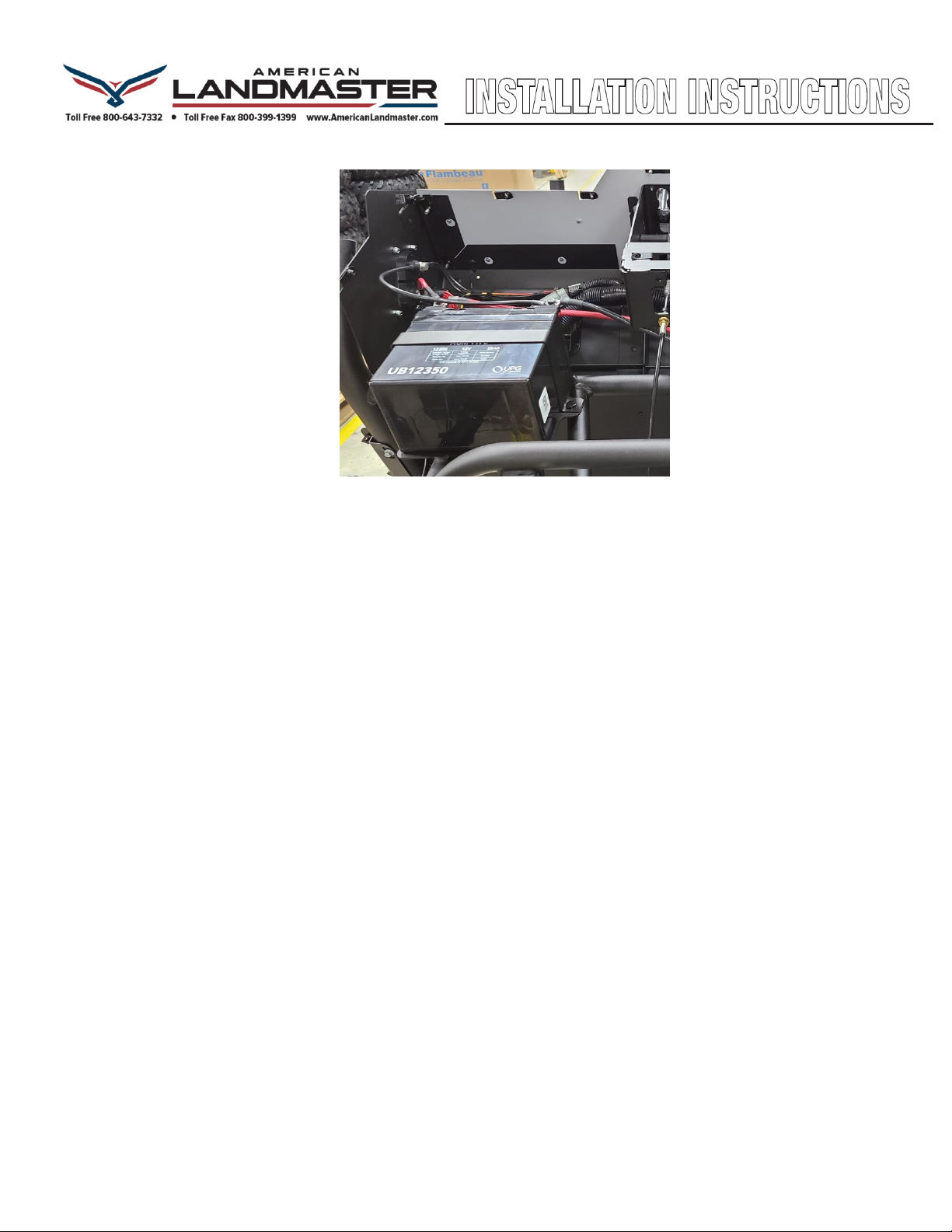
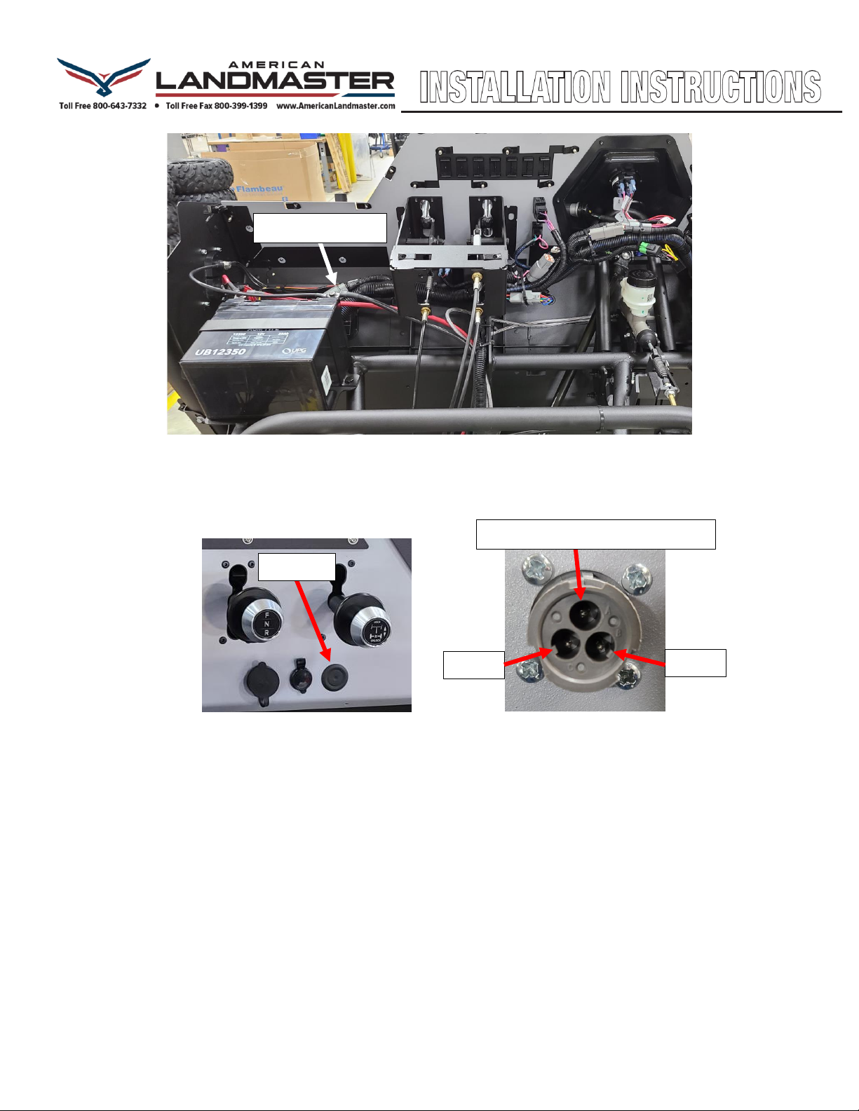
18. Reinstall the Battery and Battery Cables.
Testing the Winch:
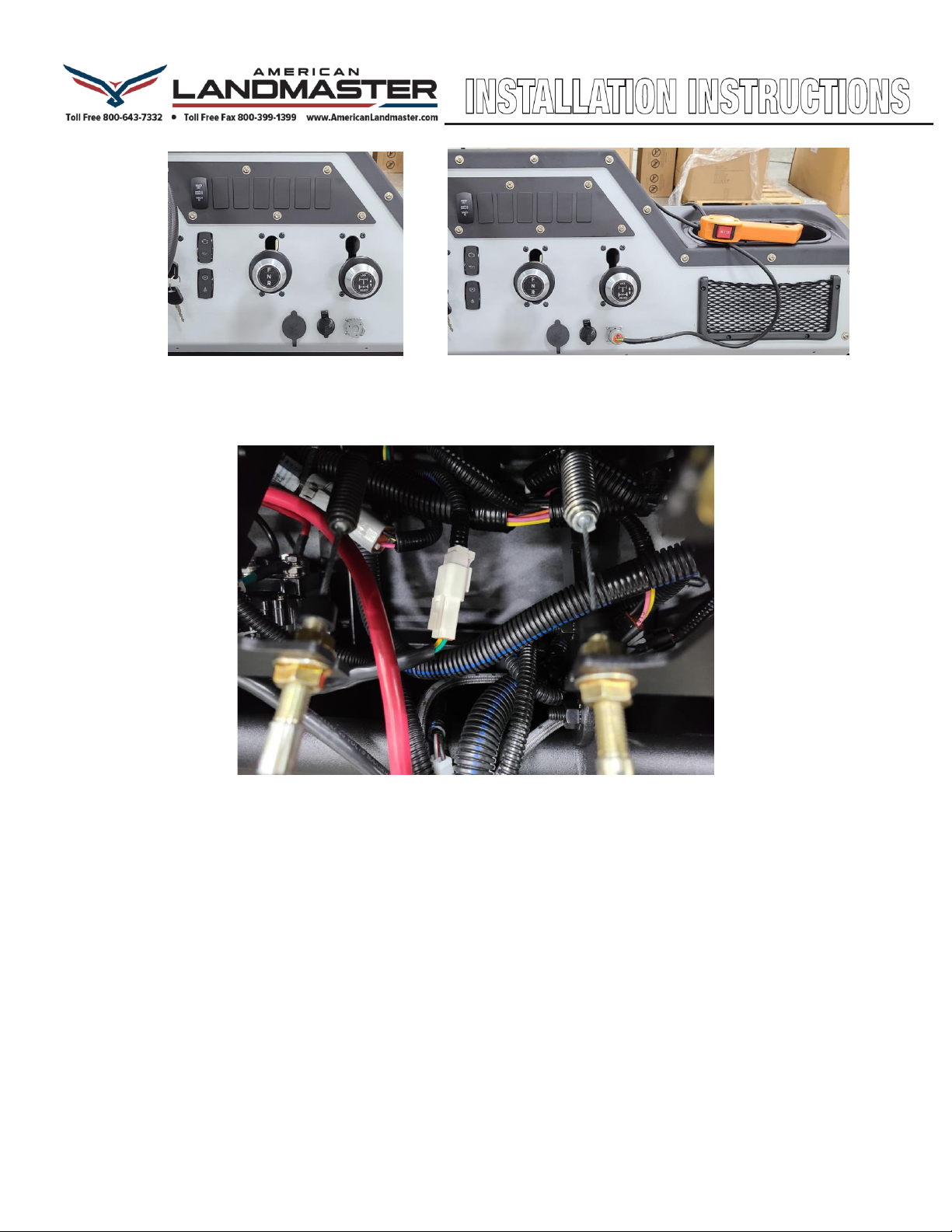
1- Turn on the Ignition key to the RUN position.
2- Depress the Winch OUT portion of the dash mounted rocker switch.
3- Verify that the winch releases the winch rope.
4- Depress the Winch IN portion of the dash mounted rocker switch.
5- Verify that the winch reels in the winch rope.
6- Attach the orange remote winch switch to the dash panel mounted three pin connector.
7- Depress the Winch OUT portion of the hand held winch switch.
8- Verify that the winch releases the winch rope.
9- Depress the Winch IN portion of the hand held winch switch.
10-Verify that the winch reels in the winch rope.
Finalizing the Installation:
1- Reinstall the black Instrument Panel Cover.
2- Reinstall the hood. Hook up front turn signal lamps, if equipped.
3- Reinstall windshield, if equipped.
Latch
Hook
Label
Other American Landmaster Winch manuals
Popular Winch manuals by other brands

Farmi Forest Corporation
Farmi Forest Corporation JL 351P OPERATION, MAINTENANCE AND SPARE PARTS MANUAL

Mile Marker
Mile Marker SEC8 ES Installation and operator's manual

Warn Industries
Warn Industries 9-C-48 Series manual

HADEF
HADEF 42/87P Installation, operating, & maintenance instructions

Warn
Warn 70924 installation instructions

POWERWINCH
POWERWINCH RC23 owner's manual