American Legend AL18 Super Legend 2019 User manual

American Legend AL18 Super
Legend
Maintenance Manual
Rev 2.0
Date of Revision: 9/27/2013
American Legend Document #: 500-MS1014

Legend Aircraft Maintenance Manual –AL18 2
© American Legend Aircraft Company Rev 2.0
Date of Revision: 9/27/2013
Table of Contents
Table of Contents.......................................................................................................................................... 2
Table of Figures............................................................................................................................................. 7
1. General................................................................................................................................................. 9
1.1. Manufacturer................................................................................................................................ 9
1.2. Physical Dimensions...................................................................................................................... 9
1.3. Three-View Drawing ...................................................................................................................10
1.4. Materials .....................................................................................................................................10
1.5. Equipment List ............................................................................................................................10
1.6. Source to Purchase Parts ............................................................................................................ 10
1.7. List of Disposable Replacement parts......................................................................................... 10
1.8. Engine Specifications .................................................................................................................. 11
1.9. Weight and Balance Information................................................................................................ 12
1.10. Tire Inflation............................................................................................................................12
1.11. Approved Oils and Capacities .................................................................................................13
1.11.1. Lycoming YO-233 ................................................................................................................13
1.12. Recommended Fastener Torque Values................................................................................. 13
1.13. General Safety Information..................................................................................................... 13
1.14. Instructions for Reporting Possible Safety of Flight Concerns during
Inspections/Maintenance.......................................................................................................................13
2. Inspections ......................................................................................................................................... 14
3. Structures ...........................................................................................................................................15
3.1. Wing ............................................................................................................................................ 15
3.1.1. Wing Removal ..................................................................................................................... 15
3.1.2. Wing Installation ................................................................................................................. 16
3.2. Empennage .................................................................................................................................18
3.2.1. Trim Jackscrew Mechanism Removal/Installation.............................................................. 18
3.2.2. Required Tools: ................................................................................................................... 18
3.2.3. Torque Tube Removal/Installation ..................................................................................... 18
3.3. Landing Gear ............................................................................................................................... 20
3.3.1. Landing Gear Removal/Installation..................................................................................... 20
3.4. Tailwheel Removal/Installation .................................................................................................. 22
3.5. Structural Control Surfaces......................................................................................................... 24

Legend Aircraft Maintenance Manual –AL18 3
© American Legend Aircraft Company Rev 2.0
Date of Revision: 9/27/2013
3.5.1. Aileron Removal..................................................................................................................24
3.5.2. Aileron Installation and Rigging ..........................................................................................26
3.5.3. Elevator Removal ................................................................................................................ 27
3.5.4. Elevator Installation and Rigging.........................................................................................28
3.5.5. Rudder Removal.................................................................................................................. 29
3.5.6. Rudder Installation..............................................................................................................31
3.5.7. Stabilizer Removal...............................................................................................................32
3.5.8. Stabilizer Installation and Rigging ....................................................................................... 32
3.5.9. Flap Removal/Installation ................................................................................................... 33
3.5.10. Flap Control Mechanism Removal/Installation................................................................... 36
4. Engine................................................................................................................................................. 37
4.1. Engine (Lycoming YO-233) .......................................................................................................... 37
4.1.1. Engine Removal/Installation ...............................................................................................40
4.1.2. Exhaust Removal................................................................................................................. 40
4.1.3. Exhaust Installation.............................................................................................................43
4.1.4. Alternator Removal/Installation .........................................................................................43
4.1.5. Spark Plug Removal/Installation .........................................................................................45
4.1.6. Oil Change ........................................................................................................................... 45
4.1.7. Other Engine Maintenance and Repair............................................................................... 46
5. Fuel System ........................................................................................................................................ 47
5.1. Fuel Tank Removal/Installation .................................................................................................. 49
5.1.1. Required Tools: ................................................................................................................... 49
5.1.2. Parts Required:.................................................................................................................... 49
5.1.3. Level of Maintenance: Line .................................................................................................49
5.1.4. Certification Required: A&P or LSA Repairman Maintenance ............................................49
5.1.5. Verification..........................................................................................................................49
5.2. Gascolator Removal/Installation ................................................................................................49
5.2.1. Required Tools: ................................................................................................................... 51
5.2.2. Parts Required:.................................................................................................................... 51
5.2.3. Level of Maintenance: Preventive ......................................................................................51
5.2.4. Certification Required: Sport Pilot Certificate or higher..................................................... 51
5.3. Fuel Gauge Removal ...................................................................................................................51
5.4. Fuel Gauge Installation ............................................................................................................... 52
5.4.1. Required Tools: ................................................................................................................... 52
5.4.2. Parts Required:.................................................................................................................... 52

Legend Aircraft Maintenance Manual –AL18 4
© American Legend Aircraft Company Rev 2.0
Date of Revision: 9/27/2013
5.4.3. Level of Maintenance: Line .................................................................................................52
5.4.4. Certification Required: A&P or LSA Repairman Maintenance ............................................52
5.4.5. Verification..........................................................................................................................52
6. Propeller............................................................................................................................................. 53
6.1. Propeller Removal, Installation, and Repair ...............................................................................53
6.1.1. Required Tools .................................................................................................................... 53
6.1.2. Required Parts..................................................................................................................... 53
6.1.3. Level of Maintenance: Line .................................................................................................53
6.1.4. Certification Required: A&P or LSA Repairman Maintenance ............................................53
6.1.5. Other Propeller Maintenance and Repair........................................................................... 55
7. Utility Systems (Heater/Vent) ............................................................................................................ 56
7.1. Description.................................................................................................................................. 56
7.2. Heater System.............................................................................................................................57
7.2.1. Removal of Heat Shroud ..................................................................................................... 57
7.2.2. Installation of Heat Shroud .................................................................................................57
7.3. Removal of cabin heat box.......................................................................................................... 57
7.3.1. Required Tools: ................................................................................................................... 57
7.3.2. Parts Required:.................................................................................................................... 57
7.3.3. Level of Maintenance: Line .................................................................................................58
7.3.4. Certification Required: A&P or LSA Repairman Maintenance ............................................58
7.4. Installation of cabin heat box......................................................................................................58
7.4.1. Required Tools: ................................................................................................................... 58
7.4.2. Parts Required:.................................................................................................................... 58
7.4.3. Level of Maintenance: Line ................................................................................................ 58
7.4.4. Certification Required: A&P or LSA Repairman Maintenance ............................................58
7.4.5. Verification..........................................................................................................................58
7.5. Ventilation System ......................................................................................................................59
7.6. Removal of Vents ........................................................................................................................59
7.6.1. Required Tools: ................................................................................................................... 59
7.6.2. Parts Required:.................................................................................................................... 59
7.6.3. Level of Maintenance: Line ................................................................................................ 59
7.6.4. Certification Required: Sport Pilot Certificate or higher..................................................... 59
7.7. Installation of Vents ....................................................................................................................59
7.7.1. Required Tools: ................................................................................................................... 59
7.7.2. Parts Required:.................................................................................................................... 59

Legend Aircraft Maintenance Manual –AL18 5
© American Legend Aircraft Company Rev 2.0
Date of Revision: 9/27/2013
7.7.3. Certification Required: Sport Pilot Certificate or higher..................................................... 59
7.7.4. Verification..........................................................................................................................59
8. Instruments and Avionics...................................................................................................................60
8.1. Description.................................................................................................................................. 61
8.2. Removal ...................................................................................................................................... 61
8.2.1. Required Tools: ................................................................................................................... 61
8.2.2. Parts Required:.................................................................................................................... 61
8.2.3. Level of Maintenance: Line .................................................................................................61
8.2.4. Certification Required: A&P or LSA Repairman Maintenance ............................................61
8.3. See owner’s manual....................................................................................................................61
8.4. Installation .................................................................................................................................. 61
8.4.1. Required Tools: ................................................................................................................... 61
8.4.2. Parts Required:.................................................................................................................... 61
8.4.3. Level of Maintenance: Line .................................................................................................61
8.4.4. Certification Required: A&P or LSA Repairman Maintenance ............................................61
8.5. Verification..................................................................................................................................61
9. Electrical System ................................................................................................................................ 62
9.1. Description.................................................................................................................................. 62
9.2. Schematic.................................................................................................................................... 62
10. Structural Repair ............................................................................................................................. 64
11. Painting and Coating .......................................................................................................................65
12. Revisions .........................................................................................................................................66
13. Feedback Form................................................................................................................................ 67
14. Misc.................................................................................................................................................68
14.1. Overhaul.................................................................................................................................. 68
14.2. Major Repairs and Alterations ................................................................................................68
14.3. Task-Specific Training.............................................................................................................. 69
14.4. Safety Directives......................................................................................................................69
14.5. Safety Alert.............................................................................................................................. 69
14.6. Service Bulletin........................................................................................................................ 69
14.7. Notification .............................................................................................................................69
14.8. Reporting Forms and 100 Hour/Annual Checklist ..................................................................70
Appendix A. Equipment List........................................................................................................................71
Appendix B. Reporting Forms ....................................................................................................................73
Appendix C. 100 Hour / Annual Checklist ...............................................................................................74

Legend Aircraft Maintenance Manual –AL18 6
© American Legend Aircraft Company Rev 2.0
Date of Revision: 9/27/2013

Legend Aircraft Maintenance Manual –AL18 7
© American Legend Aircraft Company Rev 2.0
Date of Revision: 9/27/2013
Table of Figures
Figure 1-1 Aircraft Specification............................................................................................................. 9
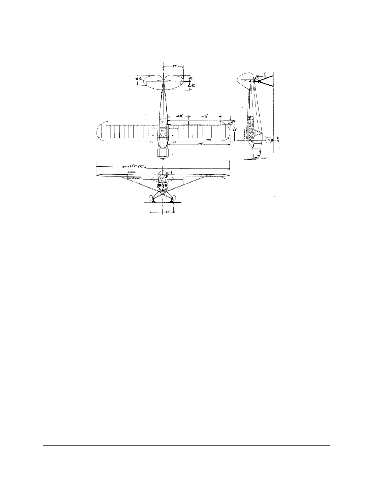
Figure 1-2 Aircraft Three View Drawing..................................................................................................... 10
Figure 1-3 Engine Specifications .......................................................................................................... 11
Figure 1-4 Sample Loading Problem ....................................................................................................12
Figure 1-5 Center of Gravity Limits ......................................................................................................12
Figure 1-6 Main Tire Inflation............................................................................................................... 12
Figure 1-7 Tailwheel Tire Inflation ....................................................................................................... 12
Figure 1-8 Lycoming YO-233 Approved Oils / Capacities..................................................................... 13
Figure 3-1 Wing View.................................................................................................................................. 15
Figure 3-2 Jackscrew ..................................................................................................................................18
Figure 3-3 Jackscrew Access .......................................................................................................................18
Figure 3-4 Torque Tube Rear ...................................................................................................................... 19
Figure 3-5 Torque Tube Front ..................................................................................................................... 19
Figure 3-6 Landing Gear.............................................................................................................................. 20
Figure 3-7 –Landing Gear Cabane / Struts ................................................................................................. 21
Figure 3-8 Landing Gear Leg ....................................................................................................................... 21
Figure 3-9 Tailwheel Rear View.................................................................................................................. 23
Figure 3-10 Tailwheel Side View ................................................................................................................. 23
Figure 3-11 Aileron Balance Cable .............................................................................................................. 24
Figure 3-12 Aileron Lower View................................................................................................................. 25
Figure 3-13 Aileron Upper View..................................................................................................................25
Figure 3-14 Elevator....................................................................................................................................27
Figure 3-15 Rudder ..................................................................................................................................... 30
Figure 3-16 Control Surface Travels ....................................................................................................... 31
Figure 3-17 Flap, Lower View...................................................................................................................... 34
Figure 3-18 Flap, Upper View...................................................................................................................... 35
Figure 4-1 Lycoming YO-233 Installation Top View .................................................................................... 37
Figure 4-2 YO-233 Gascolator .....................................................................................................................38
Figure 4-3 YO-233 Side View....................................................................................................................... 38
Figure 4-4 YO-233 Front View.....................................................................................................................39
Figure 4-5 Exhaust, Right Side.....................................................................................................................41
Figure 4-6 Exhaust, Left Side.......................................................................................................................41
Figure 4-7 Exhaust, Rear ............................................................................................................................. 42
Figure 4-8 YO-233 Alternator...................................................................................................................... 44
Figure 5-1 Fuel Tank Caps / Covers............................................................................................................. 47
Figure 5-2 Fuel Sight Gauges....................................................................................................................... 47
Figure 5-3 Fuel System Diagram ................................................................................................................. 48
Figure 5-4 Gascolator.................................................................................................................................. 50
Figure 5-5 Fuel Sight Gauges....................................................................................................................... 51
Figure 6-1 ....................................................................................................................................................54
Figure 6-2 ....................................................................................................................................................55
Figure 6-3 ....................................................................................................................................................55
Figure 7-1 Cabin Heat Inlet .........................................................................................................................56
Figure 7-2 Cabin Heat Outlet ......................................................................................................................56
Figure 8-1 Instrument Panel .......................................................................................................................60
Figure 9-1 Battery Installation ....................................................................................................................62
Figure 9-2 Electrical System Block Diagram................................................................................................ 63

Legend Aircraft Maintenance Manual –AL18 9
© American Legend Aircraft Company Rev 2.0
Date of Revision: 9/27/2013
1. General
1.1. Manufacturer
Legend Cub aircraft are manufactured by the American Legend Aircraft
Company in Sulphur Springs, Texas. USA.
1.2. Physical Dimensions
AL18
Continental YO-233
Wing Span
35’ 6”
Length
22’ 8”
Height
(standard
wheels and
prop)
7’ 6”
Empty Weight
(standard
airplane)
845 lbs
Design Gross
Weight (land)
1320
Design Gross
Weight (sea)
1430
Useable Fuel
Capacity
30 U.S. Gallons
Seating
2 Persons, Tandem
Figure 1-1 Aircraft Specification

Legend Aircraft Maintenance Manual –AL18 10
© American Legend Aircraft Company Rev 2.0
Date of Revision: 9/27/2013
1.3. Three-View Drawing
Figure 1-2 Aircraft Three View Drawing
1.4. Materials
Legend Cub aircraft uses standard aircraft quality parts and materials.
Fuselages are made from Chromalloy 4130 tubing. Wings are built with spars
and ribs made from 6061 aluminum extrusion. Fuselage, wings and control
surfaces are covered according to the Star Gloss covering system.
1.5. Equipment List
See Appendix A for the equipment list for this aircraft.
1.6. Source to Purchase Parts
Parts can be procured directly from the component manufacturer or
American Legend Aircraft Company. For example, for avionics replacement
with the same model, aircraft owner can purchase from off the shelf
suppliers.
Our part suppliers include Garmin, TruTrak, AeroLED, and JDI. For contact
information on alternate suppliers for individual components or for more
information on the supplier of a specific component, please contact American
Legend.
1.7. List of Disposable Replacement parts
See YO-233 Lycoming Illustrated Parts Catalog for list of engine related
disposable parts.

Legend Aircraft Maintenance Manual –AL18 11
© American Legend Aircraft Company Rev 2.0
Date of Revision: 9/27/2013
1.8. Engine Specifications
AL18
Lycoming YO-233
Rating
115 hp
Disposition
Normally aspirated, direct drive, air
cooled, horizontally opposed,
carbureted, four cylinder engine with
233 cu. in. displacement
Time
Between
Overhaul
2200 hours
Oil
Specification
SAEJ189 or MIL-L-2285
Oil Quantity
6 quarts maximum, 4 quarts minimum
Fuel Grade
(minimum)
100LL Aviation Fuel
Figure 1-3 Engine Specifications

Legend Aircraft Maintenance Manual –AL18 12
© American Legend Aircraft Company Rev 2.0
Date of Revision: 9/27/2013
1.9. Weight and Balance Information
Sample Airplane
Actual Airplane
Weight
Station
Moment
Weight
Station
Moment
Empty
weight
845
11.6
9800
Front
Seat
190
11
2090
11
Back
Seat
140
37
5180
37
Fuel (6.0
x 20 gal)
120
24
2880
24
Baggage
(75 lbs
max)
20
57
1140
57
Total
Aircraft
1320
16.0
21,090
Figure 1-4 Sample Loading Problem
Gross Weight
Forward Limit
Aft Limit
1320 lbs
10.5”
21.0”
Figure 1-5 Center of Gravity Limits
1.10. Tire Inflation
Main Tire
Pressure
6.00 x 6
25 psi
8.00 x 6
15 psi
26” Tundra
8 psi min
Figure 1-6 Main Tire Inflation
Tailwheel Tire
Pressure
Alaska Bushwheel TBD
TBD
Figure 1-7 Tailwheel Tire Inflation

Legend Aircraft Maintenance Manual –AL18 13
© American Legend Aircraft Company Rev 2.0
Date of Revision: 9/27/2013
1.11. Approved Oils and Capacities
1.11.1. Lycoming YO-233
Temperature
SAEJ189 OR MIL-L-2285
Capacity
Above 80°F
SAE 15W-50, SAE 20W-50 or SAE
60
4 –6 quarts
Above 60°F
SAE 40 or SAE 50
4 –6 quarts
Between 30°F and 90°F
SAE 40
4 –6 quarts
Between 0°F and 70°F
SAE 30, SAE 40, or SAE 20W-40
4 –6 quarts
Below 10°F
SAE 30 or SAE 20W-30
4 –6 quarts
Figure 1-8 Lycoming YO-233 Approved Oils / Capacities
1.12. Recommended Fastener Torque Values
American Legend uses the standard torque values as referenced in FAA
document AC 43.13 and the Lycoming, Sensenich and Service Manuals.
1.13. General Safety Information
CAUTION
WHEN PULLING THE PROPELLER THROUGH BY HAND, TREAT THE PROPELLER AS IF THE
MAGNETO/START SWITCH WERE ON. DO NOT STAND OR ALLOW ANYONE ELSE TO
STAND WITHIN THE ARC OF THE PROPELLER SINCE A LOOSE OR BROKEN WIRE OR A
COMPONENT MALFUNCTION COULD CAUSE THE ENGINE TO START.
Do not tow or push aircraft by the tail surfaces, Lift handle on the right rear side of
fuselage should be used for this purpose.
Always check oil cap, fuel caps, cowling, doors and windows for security before flight.
Always use and follow the aircraft checklist
1.14. Instructions for Reporting Possible Safety of Flight Concerns during
Inspections/Maintenance
The Service Difficulty Report is included in Appendix B of this manual. The form may also be found at
www.legend.aero.

Legend Aircraft Maintenance Manual –AL18 14
© American Legend Aircraft Company Rev 2.0
Date of Revision: 9/27/2013
2. Inspections
The 12-Month Condition / 100 Hour Inspection Checklist is included in Appendix C of the Maintenance
Manual. The latest revision of the checklist can be found on the American Legend Website at
www.legend.aero.

Legend Aircraft Maintenance Manual –AL18 15
© American Legend Aircraft Company Rev 2.0
Date of Revision: 9/27/2013
3. Structures
3.1. Wing
3.1.1. Wing Removal
3.1.1.1. Required tools:
½ inch socket/wrench
3/8 inch socket/wrench
#1 and #2 Phillips screwdriver
diagonal cutters
pliers
3.1.1.2. Parts Required:
None
3.1.1.3. Level of Maintenance: Line
3.1.1.4. Certification Required: A&P or LSA Repairman Maintenance
3.1.1.5. Removal
Drain all fuel from the airplane through the belly sump drain. Both tanks will
drain from this location.
Remove remaining fuel from each tank through the tank sump drains.
Remove all wing root fairings.
Remove aileron (See item 3.5.1, Aileron Removal)
Remove flaps and flap mechanism (See items 3.5.9, Flap
Removal/Installation, and 3.5.10, Flap Control Mechanism
Removal/Installation)
Remove nuts from the wing root attach bolts, lift strut upper attach bolts,
and lift strut lower attach bolts.
Pull the aileron direct cable out of the wing, forward strut pulley, and forward
strut fairleads.
Disconnect aileron balance cable
at the link in the cabin and pull
cable out of fuselage fairlead.
If equipped with strobe/position
lights or landing light, disconnect
wires as necessary.
Disconnect front and rear fuel
pickup lines and both fuel gage
connections.
While supporting the wing at the
tip, remove the rear strut starting
with bottom attach point first then
the front strut starting with the
bottom attach point first.
NOTE
Before removing wing, support opposite wing to prevent the aircraft from
tipping over when wing is removed.
Support the wing at the root and remove the rear wing attach bolt first then
the forward attach bolt.
Remove wing from airplane.
Figure 3-1 Wing View

Legend Aircraft Maintenance Manual –AL18 16
© American Legend Aircraft Company Rev 2.0
Date of Revision: 9/27/2013
3.1.2. Wing Installation
3.1.2.1. Required tools:
½ inch socket/wrench
3/8 inch socket/wrench
#1 and #2 Phillips screwdriver
diagonal cutters
pliers
Large Hammer
Phillips Screwdriver
3.1.2.2. Parts Required:
None
3.1.2.3. Level of Maintenance: Line
3.1.2.4. Certification Required: A&P or LSA Repairman Maintenance
3.1.2.5. Installation
To facilitate the rigging process, pre-set the forks in the front struts to eight
threads past jam nut and five threads past the jam nut on the rear struts.
Raise wing to bring spar fittings into position in the wing fittings on the
fuselage.
Install the forward bolt first then the rear bolt.
Install the forward strut beginning with the upper attach point first. Make
sure to install the tie-down ring before the strut.
With the forward strut attached to the wing, raise the wing tip and slide the
fork down on the fuselage fitting and install the bolt.
Repeat the above steps for the opposite wing.
To check dihedral angle, first insure that the fuselage is level laterally, then
stretch a string from wing tip to wing tip along the front spar.
Measure down from the string to the top of the fuselage front wing hinge
fitting. The measurement should be three inches plus or minus 1/8-inch.If
the measurement is too low, adjust the forks on the front struts an equal
amount on each side.
One half turn adjustment on both forks results in a 1/8 inch change in the
height of the string.
Once the proper measurement is obtained the wings must be checked to
insure that they are set square with the fuselage.
Assemble a tool to check the rigging by using a piece of straight aluminum
angle of sufficient thickness to not be flexible. On one end attach a metal or
wood block that is 13/22 inches thick. Place this bar with the block facing
outboard along the front spar in the area between the jury strut attach fitting
and the strut attach fitting. Place the level along this bar. The reading
should be the same on each wing. If not, it indicates that one wing is
adjusted higher than the other. To correct, shorten the strut on the high
wing side and lengthen the strut on the low wing side and equal amount.
When the level reading is the same on both sides recheck total dihedral
again with the string.
Once dihedral is set, the rear struts can be installed and the washout of each
wing set. Start by installing the rear strut on one wing. To check washout,
attach another block 3/8 inch thick to the rigging tool. Check the angle the
fuselage is sitting at by placing the digital level along the tube at the lower
door sill. This is the baseline number. Hold the tool with the 3/8 inch block

Legend Aircraft Maintenance Manual –AL18 17
© American Legend Aircraft Company Rev 2.0
Date of Revision: 9/27/2013
toward the rear along the last full rib at the outboard end of the aileron bay.
Place the level on the bar. This measurement should match the fuselage
number. If not, adjust the fork in or out until the numbers match. Repeat
the process for the opposite wing.
NOTE
It is very important that the washout of the wings be equal. If washout is
unequal it will cause the airplane to constantly bank and not fly straight.
Repeat the process for the other wing.
Attach the jury struts to the wing and the jury strut clamps to the struts.
Anti-chafe tape should be put on the jury strut clamp where it will make
contact with the strut.
The jury strut lugs and the spreader bar should be attached to the bottom of
both jury struts before attaching the lugs to the clamps on the struts.
Check the jury struts to make sure they are vertical before tightening the
clamp bolts.
Run the aileron direct cable through the fairleads on the front strut, around
the pulley and up into the wing.
Put the aileron balance cable back through the fuselage fairlead and attach
to the opposite wing cable.
Install and rig aileron (See section 3.5.2, Aileron Installation and Rigging).
Install and rig flap (See items 3.5.9, Flap Removal/Installation, and 3.5.10,
Flap Control Mechanism Removal/Installation)
3.1.2.6. Verification
Wing to fuselage bolts secure
Lift struts to wing and fuselage secure and torque sealed

Legend Aircraft Maintenance Manual –AL18 18
© American Legend Aircraft Company Rev 2.0
Date of Revision: 9/27/2013
3.2. Empennage
3.2.1. Trim Jackscrew Mechanism Removal/Installation
3.2.2. Required Tools:
½ inch wrench/socket
diagonal cutters
pliers
9/16 inch wrench/socket
#1 and #2 Phillips screwdriver
5/16 inch wrench/socket
3.2.2.1. Parts Required:
None
3.2.2.2. Level of Maintenance: Line
3.2.2.3. Certification Required: A&P or
LSA Repairman Maintenance
3.2.2.4. Trim Jackscrew Removal
First remove trim cable from the
jackscrew pulley by pulling the idler
pulley aft to relieve the cable tension.
Remove stabilizer link from the stabilizer
yolk by removing the cotter pin, nut, and
bolt on each side. The trim indicator
cable will have to be disconnected from
the link first.
Pull the cotter pin from the nut securing
the trim pulley to the jackscrew and
remove the nut and pulley.
Take out the key in the bottom of the
jackscrew.
Cut the fabric from the hole in the fairing
directly above the jackscrew.
Lift the jackscrew up through the hole
while threading the trim yolk down off
the jackscrew.
3.2.2.5. Trim Jackscrew Installation
Install in the reverse order.
A cover for the hole cut to remove the
jackscrew will have to be fabricated.
3.2.2.6.
Verify all fasteners are tight and cotter
keys are installed where required
3.2.3. Torque Tube Removal/Installation
Figure 3-2 Jackscrew
Figure 3-3 Jackscrew Access

Legend Aircraft Maintenance Manual –AL18 19
© American Legend Aircraft Company Rev 2.0
Date of Revision: 9/27/2013
Figure 3-4 Torque Tube Rear
Figure 3-5 Torque Tube Front

Legend Aircraft Maintenance Manual –AL18 20
© American Legend Aircraft Company Rev 2.0
Date of Revision: 9/27/2013
3.2.3.1. Required Tools
Pliers
3/8 socket/wrench
7/16 socket/wrench
3.2.3.2. Parts Required:
Cotter Keys
3.2.3.3. Level of Maintenance: Line
3.2.3.4. Certification Required: A&P or LSA Repairman Maintenance
3.2.3.5. Torque Tube Removal
Loosen tension on aileron and elevator cables.
Disconnect elevator cables from the torque tube.
Remove upper part of the front and back sticks.
Remove the front and rear torque tube caps. Pay attention to washer
placement to make installation easier.
Pull the aft end of the torque tube up to bring the aileron cables above the
floorboard and remove the aileron cables.
Remove the torque tube from the airplane.
Install in the reverse order.
3.2.3.6. Verification
All fasteners tight
All cotter keys installed
3.3. Landing Gear
3.3.1. Landing Gear Removal/Installation
Figure 3-6 Landing Gear
Table of contents