American Standard BAYECON101A Assembly instructions

Model:
BAYECON101A
BAYECON102A
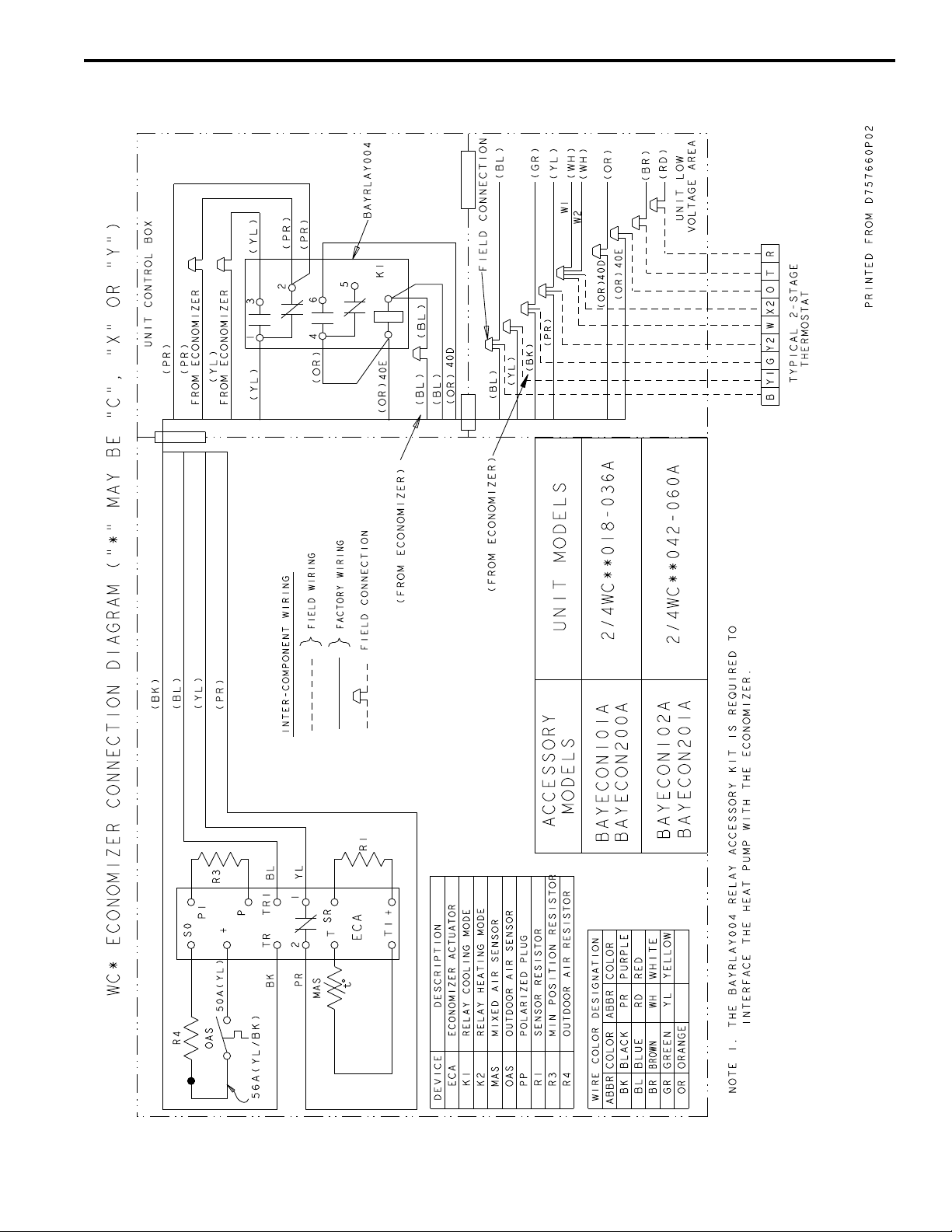
BAYRLAY004A (Relay required in WC* Units)
Down Discharge Economizer and Rain Hood
Used with:
2/4TC*,WC*,YC*,DC* *018-036A
2/4TC*,WC*,YC*, DC* *042-060A
Inspect Contents
You must report damage and make claims to the transporta-
tion company immediately. Report missing parts to your sup-
plier immediately and replace with authorized parts only.
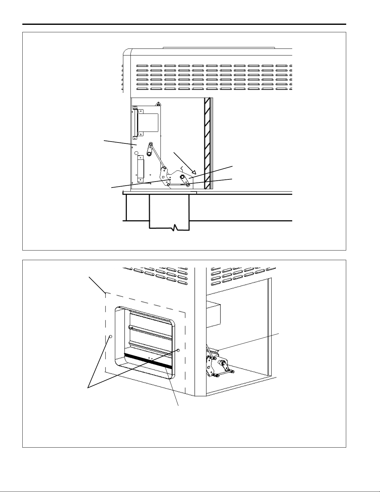
3. Install Economizer Assembly
Note: You must first install the filter rack per the instruc-
tions provided and then install the economizer.
2. Swing the return air damper section down so that it rests
on the bottom of the unit. The economizer will sit
completely over the return air opening in the bottom of
the unit. See Figures 5 on page 4. Screw the economizer
assembly together with one assembly screw in the side of
the economizer. Tighten the linkage rod between the
return air dampers.
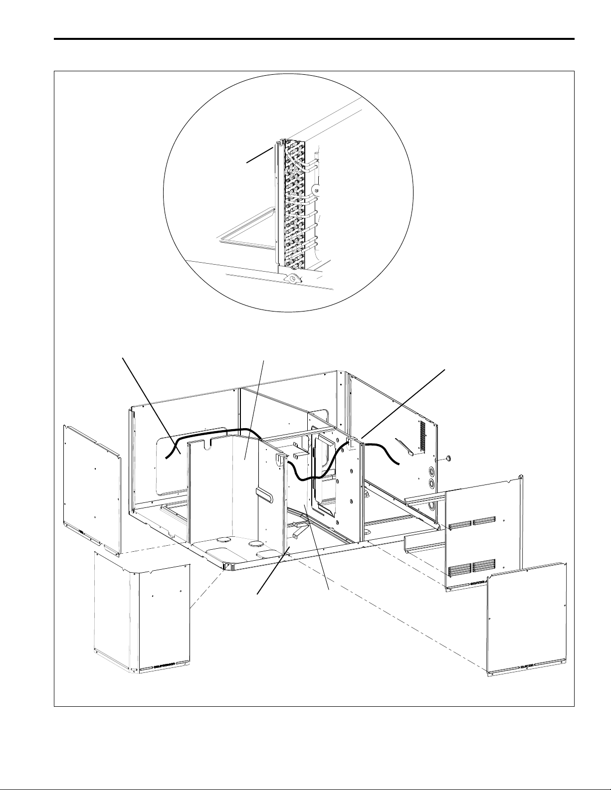
3. Insert 2 screws through the holes in the front face of the
unit and into the matching attachment holes in the econo
mizer assembly. See Figure 6 on page 4.
4. Insert a screw through the pre-punched hole in the side
flange of the return air damper and into the mating hole
in the economizer assembly and tighten. See Figure 5 on
page 4.
18-HE39D8-7
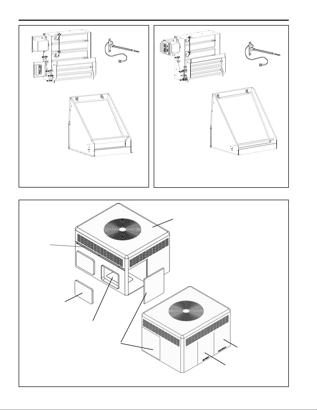
Identify Economizer Kit Contents
Refer to Figures 1 and 2 on page 2 to identify the kit
contents.
Install Economizer Kit
General
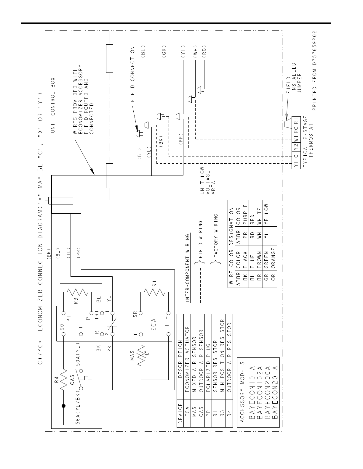
The economizer is a multi-damper design. It is installed in the
return air stream and is connected to the unit low voltage sup-
ply through wire leads. The economizer is fully accessible
through the Coil access panel.
Important: The Economizer installation requires that you first
install an air filter rack ordered separately. Use:
BAYFLTR101A for 2/4YC*, WC*, TC*, DC* *018-3036A
BAYFLTR201A for 2/4YC*, WC*, TC*, DC* *042-3060A.
1. Remove Power
Disconnect and verify that power is off.
2. Remove Access Panels
Remove these four (4) access panels (see Figure 3, page 2):
• Control/Heat access panel
• Blower access panel
• Coil access panel
• Horizontal Return Air panel (discard or store)
When the economizer is installed in WC* models, relay
accessory kit BAYRLAY004A is required. Refer to the drawing
on page 9 to make your relay wiring connections in the Control
Box.
Installer’s Guide
ALL phases of this installation must comply with NATIONAL, STATE AND LOCAL CODES
IMPORTANT — This Document is customer property and is to remain with this unit. Please return to service
information pack upon completion of work.
HAZARDOUS VOLTAGE - DISCONNECT POWER BEFORE SERVICING
WARNING:
ELECTRIC SHOCK HAZARD
OPEN AND LOCK OUT ALL UNIT DISCONNECTS PRIOR TO
ACCESSORY INSTALLATION OR UNIT MAINTENANCE, TO
PREVENT INJURY OR DEATH FROM ELECTRICAL SHOCK OR
CONTACT WITH MOVING PARTS.
SAFETY HAZARD
DO NOT REMOVE END COVERS FROM ECONOMIZER AC-
TUATOR; THE SPRING-RETURN ASSEMBLY MAY RELEASE
AND CAUSE PERSONAL INJURY.
WARNING
!
!
WARNING
Use care when inserting the economizer in the return air com-
partment, to prevent damaging the foil faced insulation.
CAUTION
!
1. The economizer ships with the return air damper folded
up to allow the assembly to fit through the Coil opening
in the side of the unit, see Figures 1 and 2 on page 2.
Insert the economizer assembly into the unit through the
Coil access panel opening. See Figure 4 on page 3.

PAGE 2
INSTALLER’S GUIDE
Mixed Air Sensor
Economizer Assembly
Rainhood Assembly
Figure 1. Economizer Kit Components
YC*, TC*, WC*, DC* *018A to *036A
Figure 2. Economizer Kit Components
YC*, TC*, WC*, DC* *042A to *060A
Figure 3. Remove Panels
DC, TC, WC,
or YC Unit
Horizontal
Return Air
Panel
Down Flow
Return Air
Panel
Blower Access Panel
Control Box Access
Panel
Coil Access
Panel
Mixed Air Sensor
Economizer Assembly
Rainhood Assembly
Mist
Eliminator
(Filter)
Mist
Eliminator
(Filter)
Return Air Damper
Flange Screw and
two (2) Mixed Air
Sensor
Sheetmetal Screws
(not shown)
Top Sealing
Flange
Return Air Damper
Flange Screw and
two (2) Mixed Air
Sensor
Sheetmetal Screws
(not shown)

PAGE 3
INSTALLER’S GUIDE
4. Install Rain Hood Assembly
1. Locate the rainhood assembly, which includes the relief damper
and the mist eliminator. The back of the hood side mating flanges
need to be gasketed (gaskets included in kit). Loosen the right
two (2) screws on the unit’s top sealing flange above the
economizer. See Figure 3 on page 2.
2. Slide the top flange of the hood up underneath the unit’s top
sealing flange. Drive two self tapping screws into the keyhole
openings on the side flanges of the hood.Tighten the two (2)
screws on the top sealing flange and the screws on the hood side
flanges. See Figures 8 and 9.
5. Mount Mixed Air Sensor
1. Mount the Mixed Air sensor (with wiring) to the left Blower
partition using two sheetmetal screws. See Figure 10. The male
tabs on the two (2) yellow wires will connect to the Economizer
wiring harness in a later step.
2. Enthalpy and/or CO2 Sensor--If used, install these options at
this time per instructions provided.
6. Route Main Wiring
1. From the Economizer assembly, pass the wire harness through
the coil grommet. See Figure 10 (view A) on page 7. Continue
routing the harness behind the Compressor compartment and into
Figure 4. Insert Economizer in Shipping Position
DC, TC, YC, or WC
Unit
Dry bulb outside air
temperature sensor
Insert economizer
in folded shipping
position
Economizer
actuator and
controller
the Blower compartment.
2. Continue routing the remaining harness through the grommet in
the Control Box partition and into the Control Box.
7. Complete Installation
1. In the Control Box, complete the wiring connections per the
appropriate wiring diagram on pages 8 and 9. Secure all wires so
that there is no interference with any moving parts in the unit.
2. Power the economizer and run the checkout procedure on page
10. Make desired adjustments to the controller setting the
minimum occupied damper position, the outside air setting (if
enthalpy used), and the IAQ sensor (if used).
3. Replace the unit Coil access panel, the Blower access panel, and
the Control/Heat access panel.

PAGE 4
INSTALLER’S GUIDE
Figure 5. Swing Down and Set Economizer Return Air Damper
Economizer
2.) Insert Assembly
screw
1.) Swing
Down
Return Air
Damper
Return Air Damper
3.) Tighten Linkage rod
Figure 6. Start Economizer’s Front Mounting Screws
Economizer outline
Install two (2)
screws into holes.
Leave extended
from unit 1/2”.
Economizer and
Return Air Damper
Apply gasket between damper assembly and hood.

PAGE 5
INSTALLER’S GUIDE
1. Loosen the two
(2) screws to allow
hood to slide under
top sealing flange
of the unit.
Detail
Economizer rain
hood
Figure 7. Mounting Rain Hood
Top flange of hood
slides under HVAC
unit’s top sealing
flange HVAC unit’s top
sealing flange
Hood HVAC unit
2. Drive six (6) self
tapping screws into
the keyhole openings
on each side of hood
flanges.
Unit’s top sealing
flange
3. Tighten the two
(2) top screws and
the two (2) side
screws.

PAGE 6
INSTALLER’S GUIDE
Figure 8. Rain Hood, Economizer, and Filter
Figure 9. Mount Mixed Air Sensor in Blower Compartment
1.80"
2.82"
View ‘A’ Approximate
Mounting Dimension
See View ‘A’
Return Duct Roofcurb
Relief damper
Mist eliminator
(filter)
Economizer rain
hood
Outside air
dampers
Return air
dampers Required filter
kit, order
separately
Mount the Mixed Air
Sensor to the partition
using two (2) sheetmetal
screws. See View A for
approximate positioning.

PAGE 7
INSTALLER’S GUIDE
Figure 10. Main Wire Harness Routing
1.) From EconomizerAssembly, Pass Wire
Harness Through Coil Grommet. See View
A.
View ‘A’
2.) Continue Routing Behind Compressor
Compartment and into Blower Compart-
ment.
3.) Pull the two (2) Mixed Air
Sensor Wires (with female quick
connects) from the Harness and
Route Down Near the Mixed Air
Sensor. Connect to sensor
pigtail wire leads.
Location of
Mixed Air Sensor
4.) Continue Routing the Remain-
ing Harness Through the Grommet
and into the Control Box.
Coil Grommet

PAGE 8
INSTALLER’S GUIDE
Figure 11. TC*/YC* Economizer Connection Diagram

PAGE 9
INSTALLER’S GUIDE
Figure 12. WC* Economizer Connection Diagram

PAGE 10
INSTALLER’S GUIDE
5. Checkout
SINGLE ENTHALPY CHANGEOVER SET POINT
Single enthalpy: The enthalpy
changeover set point is set to return the
outdoor air damper to minimum posi-
tion when the enthalpy rises above its
set point. The enthalpy set point scale
markings, located on W7459, are
A,B,C,D; see table for the correspond-
ing control point. The factory-installed
R4 WHITE 620-ohm jumper must be in
place across terminals + and SR.
Operate the motor through its complete open-close stroke. If
necessary, release one of the previously tightened linkage con-
nections to prevent damage. Check for proper operation, making
sure that the linkage does not bind and that the motor travels
smoothly throughout its fully open and closed position. Table 1
describes how to drive the motor to the full open and full closed
positions (power connected). If there is excess length of linkage
rod, cut it to size. Make necessary minor adjustments until
desired operation is obtained, and tighten all nuts and set screws.
This motor checkout ensures that:
1. The motor operates the load.
2. The motor responds properly to the controller.
3. There is no binding of the linkage or motor stalling at any
point of travel.
If motor does not operate properly, check for proper voltage or
mechanical binding in linkage or damper.
If questions arise regarding this product, contact your distributor
or representative.
CONTROL
CURVE
A
B
C
D
CONTROL POINT
APPROX. F ( C)
AT 50% RH
73 (23)
70 (21)
67 (19)
63 (17)
12 14 16 18 20 22 24 26 28 30 32 34 36 38 40 42 44 46
90
100
80
70
60
50
40
30
20
10
ENTHALPY—BTU PER POUND DRY AIR
85
(29)
90
(32)
95
(35)
100
(38)
105
(41)
110
(43)
35
(2)
35
(2)
40
(4)
40
(4)
105
(41)
110
(43)
45
(7)
45
(7)
50
(10)
50
(10)
55
(13)
55
(13)
60
(16)
60
(16)
65
(18)
65
(18)
70
(21)
70
(21)
75
(24)
75
(24)
80
(27)
80
(27)
85
(29)
90
(32)
95
(35)
100
(38)
APPROXIMATE DRY BULB TEMPERATURE— F ( C)
A
A
B
B
C
C
D
D
M11681
RELATIVE HUMIDITY (%)
1
1
HIGH LIMIT CURVE FOR W7459D.
MODEL DRIVE MOTOR OPEN DRIVE MOTOR CLOSED SPRING RETURN
M7415 Power to TR and TR1, jumper T and T1. Disconnect jumper at T or T1 and
disconnect P or P1,if connected. Disconnect power at TR and TR1.
Table 1. Motor Operation Checkout

PAGE 11
INSTALLER’S GUIDE
1
1
2
2
M9097
ENTHALPY CHANGEOVER
SETPOINT
LED LIGHTS WHEN
OUTDOOR AIR IS SUITABLE
FOR FREE COOLING
INSERT DC MILLIAMMETER BETWEEN SOAND S FOR CHECKOUT
AND TROUBLESHOOTING.
JUMPER USED FOR SINGLE ENTHALPY CONTROL.
TR TR1
A
BC
D
SO
SR
+
+
+
C7400
620 OHM
JUMPER
DC
MILLIMETER
W7459
S
+
1
1
M9098B
ENTHALPY
CHANGEOVER
SETPOINT
MINIMUM
DAMPER
POSITION
SETTING
LED LIGHTS
WHEN OUTDOOR
AIR IS SUITABLE
FOR FREE COOLING
MINIMUM DAMPER POSITION ADJUSTMENT
IS PRESENT ONLY ON W7459A,D MODELS.
Meter Location for Checkout and Troubleshooting
Location of Enthalpy Set Point, Minimum Posi-
tion and LED
Table 2. Enthalpy Checkout Procedure
Figure 13. Enthalpy LEDs and Checkout
Checkout Procedure Response
A1. Disconnect power at TR and TR1.
2. Disconnect jumper P to P1.
3. Jumper TR to 1.
4. Jumper T1 to T.
5. If connected, remove C7400 Solid State Enthalpy Sensor
from teminals S0 and +. Ensure factory-installed 620 ohm
resistor is connected to terminals Sr and +.
6. Apply power (24Vac) to terminals TR and TR1
LED is off.
Motor is in closed position.
B1. Disconnect factory-installed 620 ohm resistor from
terminals Sr and +. Led turns on, motor drives toward open.
C 1. To simulate high and low enthalpy (single enthalpy
sensor) reconnect factory-installed 620 ohm resistor from
termonals Sr and +. Connect 1.2K ohm 4074EJM Checkout
Resistor across terminals So and +.
__
2. Turn enthalpy setpoint potentiometer to "A". LED turns on, indicating low enthalpy.
Motor drives toward open.
3. Turn enthalpy setpoint potentiometer to "D". LED turns off, indicating high enthalpy.
Motor drives toward closed.
4. Disconnect the 1.2 K ohm checkout resistor. __
D1. To verify sensor operation, reconnect the + lead of the
outdoor enthalpy sensor to the + terminal of W7459. __
2 Connect a DC millimeter between terminal So of the
W7459A and terminal S of the enthalpy sensor. See Fig. 10
(positive meter lead to terminal S of the enthalpy sensor).
Millimeter indication is between 3 and 25
mA if sensor is operating properly.
If millimeter indicates zero, the sensor may
be wired backward.
3. When using differential enthalpy, check the return air
enthalpy sensor by connecting a DC millimeter between
terminal Sr of the W7459A and terminal S of the return air
enthalpy sensor. (positve meter lead to terminal S of the
enthalpy sensor).
Millimeter indication is between 3 and 25
mA if sensor is operating properly.
If millimeter indicates zero, the sensor may
be wired backward.

PAGE 12
INSTALLER’S GUIDE
American Standard Inc.
6200 Troup Highway
Tyler, TX 75707-9010 The manufacturer has a policy of continuous product and
product data improvement. It reserves the right to change
design and specification without notice.
© 2007 American Standard Inc. All rights reserved
This manual suits for next models
2
Table of contents
Other American Standard Air Conditioner Accessories manuals
Popular Air Conditioner Accessories manuals by other brands

Friedrich
Friedrich PXSB 23020/30 installation instructions

Mitsubishi Electric
Mitsubishi Electric PLP-6EAJ installation manual

Sinclair
Sinclair SYMPHONY MS-H09AISW PT user manual

GE
GE RAB24 installation instructions

Fujitsu
Fujitsu UTY-XWZXZ3 installation manual

Panasonic
Panasonic nanoe CZ-CNEXU1 operating instructions