Johnson Controls PD-75A User manual

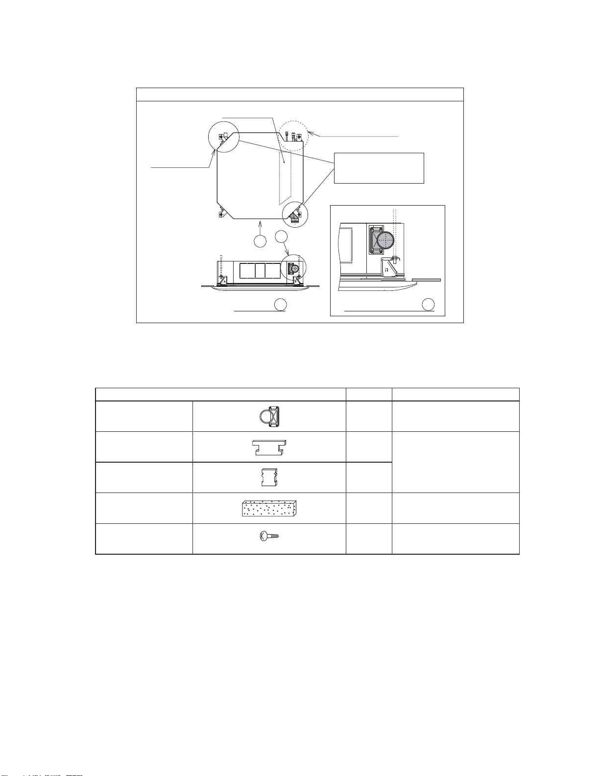
Installation Manual for Duct Adaptor (for 4-Way Cassette Type)
Model PD-75A
NOTE:
The applicable indoor unit may be different depending on the product series.
Refer to the product catalog for applicable indoor unit models.
IMPORTANT NOTICE:
●Johnson Controls pursues a policy of continuous improvement in design and performance of products. We
reserve the right to vary specifications without notice.
●No part of this manual may be reproduced without Johnson Controls’ written permission.
●Keep this manual for future reference.
●Johnson Controls cannot anticipate every possible circumstance that might involve a potential hazard.
●This kit is designed for a combination of Johnson Control air conditioners. Do not use this kit by itself or in
combination with other companies’ air conditioners.
●Perform a test run after installation to check for abnormalities.
●Signal words are used to identify levels of hazard seriousness. Definitions for identifying hazard levels are
provided below with their respective signal words.
: Indicates a hazardous situation that, if not avoided,
will result in death or serious injury.
: Indicates a hazardous situation that, if not avoided,
could result in death or serious injury.
: Indicates a hazardous situation that, if not avoided,
could result in minor or moderate injury.
: Indicates information considered important, but not hazard-related
(e.g. messages relating to property damage).
NOTE : Indicates an useful information for operation and/or maintenance.
●It is assumed that this kit will be installed and serviced by English speaking people. If this is not the case,
the customer should add safety, caution and operating signs in the native language.
●If you have any questions, contact your distributor or contractor.
●This manual gives a common description and information for this kit, as well as for other model you may
operate.
●This manual should be considered a permanent part of the air conditioning equipment and should remain
with the air conditioning equipment. Forward this information to the building owner and request that they
maintain all the equipment manuals.
1

1. Factory-Supplied Accessories
This duct adaptor is used as the connection flange to install the fresh air intake duct.
Installation Position
Electrical Box
Drain Pipe Side
View from A Enlarged View from B
B
A
Install the duct adaptor
to the opposite side of
the drain piping side.
Indoor Unit
Refrigerant Pipe Side
Unit: inch (mm)
Accessory Qty. Purpose
Duct Adaptor 1-
Insulation A 2
For Covering Gap between
Insulation and Side Plate
Insulation B 2
Insulation 1For Prevention of
Condensation
Screw
(M4 x 13/32 (10) Truss)
4 For Installation
2

2. Installation
(1) Attach the duct adaptor to the indoor unit according to the following procedures.
< Procedures >
1Cut off the knockouts from the side plate using shears.
2Cut off the insulation (Polystyrene) along the notch using a knife or something similar.
3Remove burr after the cutting work. (Be careful not to let swarf enter inside of the indoor unit.)
4Remove swarf after cutting off the insulation (Polystyrene).
Refrigerant Pipe
Side
Indoor Unit
Insulation
Side Plate
Knockout
Notch of Insulation
(Polystyrene)
(Polystyrene)
●Do not insert the knife more than 1-3/16inch
(30mm) into the insulation (Polystyrene) when
cutting off the insulation.
Do not cut off the Apart in Fig. 2.
●Do not use any tools which produce a lot of
swarf such as a saw for the opening work.
The drain pipe can become clogged and
cause water leakage.
(2) Place the insulation A and B to cover the entire gap between the side plate and the insulation (Polystyrene).
Attach the insulation A to the left and right of the opening and the insulation B to the top and bottom of
the opening.
Be careful not to cover the screw hole at the indoor unit side during placement.
Indoor Unit Insulation A
Insulation B
Place the insulations to fit
the corner of the opening.
Insulation B
Insulation A
Perform this work correctly. Otherwise, condensation may occur when cold air enters any gap left between
the side plate and the insulation (Polystyrene).
Fig. 1 Position of Insulation Placement
Insulation A
Insulation B
A
A
BB
19/32
(15)
Do not cut off this part. A
Insulation
(Polystyrene)
Side Plate
Insulation B
19/32
(15)
19/32
(15)
Insulation (Polystyrene)
Insulation A
Side Plate
B -B
Place the insulations to cover
the entire gap between the
side plate and the insulation
(Polystyrene).
A - A
Fig. 2 Cross Section of Insulation Placement
Unit: inch (mm)
3

© 2015 Johnson Controls, Inc.
Code No. LIT-12012101
Issued April, 2015
P5415552
(3) Secure the duct adaptor using four screws. (4) Wrap whole parts from the band for the
flexible duct to the resin part of the duct
adaptor with the insulation.
Tighten the band to secure the flexible duct. (Field-Supplied, Tightening Torque: 108 ft●lbs. (147 N●cm))
Fixing Plate
Indoor Unit
Screws (Four)
Duct Adaptor
Upper Surface
Wrap the flexible duct with the insulation
so it touches the indoor unit.
Table of contents
Popular Air Conditioner Accessories manuals by other brands

Samsung
Samsung MIM-H04U User & installation manual

ActronAir
ActronAir CP05 Operation manual

HMS Networks
HMS Networks AC Cloud Control Configuration

Lennox
Lennox VRF VEHD019N432U Installation & operation instructions

Galletti
Galletti Estro quick start guide

Tecnosystemi
Tecnosystemi VEGA MASTER user manual