Unitary products group 2CE Series User manual

Unitary Products Group
ACCESSORY KIT INSTALLATION INSTRUCTIONS
FUSE BLOCK ACCESSORY
MODELS 2FB04700825 & 2FB04700846 (SERIES “2CE” ELECTRIC HEATERS)
FOR SINGLE PACKAGE AIR CONDITIONERS 3 THRU 6 TON
SINGLE PACKAGE HEAT PUMPS 3 THRU 5 TON
035-19457-000-B-0403
GENERAL
The following instruction provides all the necessary informa-
tion for field assembling a fuse block accessory on the air
conditioners and heat pumps listed above.
When required by local code (Chicago), these fuse block
accessories are used in conjunction with the specific electric
heat accessory listed in Table 1 plus the equivalent heating
option if factory installed.
The following heaters include a fuse box as standard equip-
ment:
• all 208/230-1-60 heaters
• all 208/230-3-60 heaters above 8KW
Heaters with 575 voltages do not have fuse boxes. (Not
required by CSA nor any Canadian local codes.)
INSTALLATION
INSTALLATION FOR DCE/DHE/DEE/DHC/DHB 036
THRU 076 PACKAGED COOLING UNITS AND
BCH/BCB 036 THRU 060 PACKAGED HEAT
PUMPS.
Install the fuse block accessories as follows:
NOTE: Most of the following installation procedures are
duplicates of the electric heater accessory instal-
lation procedures. Refer to “For Heaters With A
Fuse Box” section in the installation instruction.
1. Disconnect all electrical power to the unit.
2. Remove the following panels from the basic unit.
• Heating access panel
• Heater control box cover
• Blower access panel
• Unit control box access panel
TABLE 1: ACCESSORY APPLICATION
Fuse Block
Accessory
Model
ELECTRIC HEATER
MODEL VOLTAGE
2FB04700825 2CE04510525
2CE04510725 208/230-3-60
2FB04700846
2CE04510746
2CE04511046
2CE04511546
2CE04512046
2CE04513046
460-3-60
FIGURE 1 - TYPICAL FUSE BLOCK INSTALLATION FOR DCE/DHE/DEE/DHC/DHB 036 THRU 076 PACK-
AGED COOLING UNITS AND BCH/BCB 036 THRU 060 PACKAGED HEAT PUMPS
FIELD
POWER
WIRING
1M
CONTACTOR
2TB
TERMINAL
BLOCK
UNIT
CONTROL
BOX
FUSE BOX FUSE BLOCK
AND
FUSES
ELECTRIC HEATER
WIRING
BLOWER
SECTION
ELECTRIC HEAT
SECTION
HEATER
CONTROL
BOX

035-19457-000-B-0403
Unitary Products Group 2
NOTE: Motor leads are held to the blower by plastic ties.
Do not disturb the ties.
3. Remove the 1-3/4” knockout from the right hand side of
the unit’s main control box. Insert the plastic bushing pro-
vided into the knockout hole from the blower section side
of the control box. The retaining collar on the bushing
MUST be onthe blower side of the control box for proper
fuse box fit-up.
4. Mount the fuse box (containing the fuse block and fuses)
inside the blower section. Attach the upper left hand
flange on the fuse box to the back of the main control
box with one screw provided.The mounting hole is
located above the 1RC capacitor. Attach the bottom right
hand flange on the fuse box to the unit 1 base, at the
holes provided, with two screws.See Figure 1.
NOTE: If insulation grip nail fasteners on the base of the
blower section interfere with proper mounting of
the fuse box, they should be broken off.
5. Open the hinged fuse box cover to gain access to the
inside. Insert the three power leads from the heater har-
ness through the hole in the right-hand side of the fuse
box and through the cable connector.This connector is
supplied with the heater kit to secure the power leads to
the fuse box. Position connector so that the connector
nut is located on the outside of the fuse box. Tighten nut.
NOTE: Wrap leads with a minimum of 3 layers of tape
where they come in contact with the connector.
DO NOT tighten the connector clamp screws until
the leads are connected and in place.
6. Insert the three (3) power leads from one side of the fuse
block to the top terminals of the terminal block (2TB)
through the bushing installed in Step 3. Connect the
three (3) power leads from the heater harness in Step 5
to the opposite side of the fuse block. Refer to the wiring
labels inside of the fuse box cover for proper wiring con-
nections.
7. Adjust all wires for the proper slack, now tighten the
screws on the connector clamp to secure in position.
8. Connect the field power wiring to the bottom terminals of
the terminal block (2TB).
9. Close fuse box cover, replace cover on the heater con-
trol box and re-install the unit panels that were removed
in Step 2.
10. Reconnect power to the unit.
FIGURE 2 - TYPICAL FUSE BLOCK INSTALLATION FOR DM/DF/DH 036 THRU 076, DL/DS/DU -03 THRU
-A6 PACKAGED COOLING UNITS AND BQ 036 THRU 060, BB -03 THRU -05 PACKAGED HEAT
PUMPS.
UNIT
CONTROL
BOX
MAIN
DISCONNECT
OR
TERMINAL
BLOCK
1M
CONTACTOR
BLOWER
SECTION
ELECTRIC HEAT
SECTION
FIELD
POWER
WIRING
FUSE BOX
HEATER
CONTROL
BOX
FUSE BLOCK
AND
FUSES
ELECTRIC HEATER
WIRING
Exercise care when securing the fuse box in posi-
tion to make sure that the evaporator low tempera-
ture sensor control leads are not pinched or cut. If
leads must be routed away from sheet metal
edges, visually check the control to insure its loca-
tion has not been disturbed.

035-19457-000-B-0403
3Unitary Products Group
INSTALLATION FOR DM/DF/DH 036 THRU 076,
DL/DS/DU -03 THRU -A6 PACKAGED COOLING
UNITS AND BQ 036 THRU 060, BB -03 THRU -05
PACKAGED HEAT PUMPS.
Install the fuse block accessories as follows:
NOTE: Most of the following installation procedures are
duplicates of the electric heater accessory instal-
lation procedures. Refer to ”For Heaters With A
Fuse Box” section in the installation instruction.
1. Disconnect all electrical power to the unit.
2. Remove the following panels from the basic unit.
• Heating access panel
• Heater control box cover
• Blower access panel
• Unit control box access panel
NOTE: Motor leads are held to the blower by plastic ties.
Do not disturb the ties.
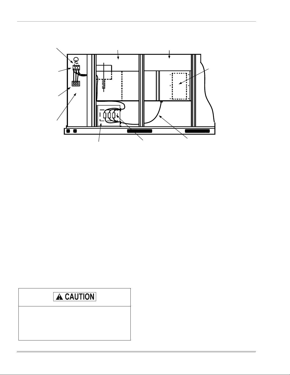
3. Mount the fuse box (containing the fuse block and fuses)
inside the blower section. Attach the upper left hand
flange on the fuse box to the back of the main control
box with one screw provided.The mounting hole is
located about 6” up from the bottom of the control box in
the rounded corner of the box. Attach the bottom right
hand flange on the fuse box to the unit base, at the holes
provided, with screws provided. See Figure 2.
NOTE: If insulation grip nail fasteners on the base of the
blower section interfere with proper mounting of
the fuse box, they should be broken off.
4. Disconnect heater power wiringharness from the bottom
terminals of the unit disconnect or terminal block in the
unit control box.
5. Loosen the electrical connector holding the heater power
harness and remove the harness from the connector.
6. Open the hinged fuse box cover to gain access to the
inside. Insert the three (3) power leads from the heater
harness through the bottom hole in theright-hand side of
the fuse box and through the electrical connector. This
connector is supplied with the fuse block kit to secure the
power leads to the fuse box. Position connector so that
the connector nut is located on the outside of the fuse
box. Tighten nut.
NOTE: Wrap leads with a minimum of 3 layers of tape
where they come in contact with the connector.
NOTE: DO NOT tighten the connector clamp screws until
the leads are connected and in place.
7. Connect the three (3) power leads of the heater harness
removed in Steps 4 thru 6 to the bottom terminals of the
fuse block.
8. Insert one end of the three (3) power leads from the fuse
block kit through the top hole in the right-hand side of the
fuse box and through the electrical connector. This con-
nector is supplied with the fuse block kit to secure the
power leads to the fuse box. Position connector so that
the connector nut is located on the outside of the fuse
box. Tighten nut.
NOTE: Wrap leads with a minimum of 3 layers of tape
where they come in contact with the connector.
NOTE: DO NOT tighten the connector clamp screws until
the leads are connected and in place.
9. Insert the other end of the three (3) power leads from the
fuse block kit into the cable connector in the unit control
box.
10. Connect the three (3) power leads that were inserted in
the fuse box, to the top terminals of the fuse block.
11. Connect the three (3) power leads that were inserted in
the unit control box, to the bottom terminals of the unit
disconnect or terminal block. Refer to the wiring labels
inside of the fuse box cover for proper wiring connec-
tions.
12. Adjust all wires for the proper slack, now tighten the
screws on the connector clamp to secure in position.
13. Close fuse box cover, replace cover on the heater con-
trol box and re-install the unit panels that were removed
in Step 2.
14. Reconnect power to the unit.
Exercise care when securing the fuse box in posi-
tion to make sure that the evaporator low tempera-
ture sensor control leads are not pinched or cut. If
leads must be routed away from sheet metal
edges, visually check the control to insure its loca-
tion has not been disturbed.

Subject to change without notice. Printed in U.S.A. Supersedes: 035-19457-000-A-0303
Copyright © by Unitary Products Group 2003. All rights reserved. 035-19457-000-B-0403
Unitary 5005 Norman
Products York OK
Group Drive 73069
This manual suits for next models
9
Other Unitary products group Air Conditioner Accessories manuals
Popular Air Conditioner Accessories manuals by other brands

Bard
Bard WGEIFM-3C installation instructions

Toshiba
Toshiba TCB-LK2801DP-UL installation manual

Intesis
Intesis AC Cloud Control Quick install guide

Galletti
Galletti EYBV quick start guide

Carrier
Carrier OSK102/EU Installation & owner's manual

Mitsubishi Electric
Mitsubishi Electric PAC-SNH21HS-E installation manual