INABA DENKO DSH-UP20E20E-07 User manual

-1-
To users
●Be sure to ask a specialist contractor for installation.
●Keep this instruction manual in a safe place.
●If you have any questions, please contact our sales representative.
1 Read first.
This product is an exclusive hose for drain-up piping of commercial A/C. Do not use for other piping.
Request
If the following procedures will not be executed, the expected functions and
performance of the product may not be demonstrated.
●The starting height of the hose shall be less than or equal to the maximum starting height specified by the air conditioner
manufacturer.
●This piping is exclusive for indoor use. Do not use the product outdoors.
2 Precautions for proper and safe use
The following explains how to ensure in order to prevent harm to the users and others and damage to property.
The degree of harm or damage caused by the incorrect use of the product by ignoring the labeling is classified by the
following labeling.
Notification
Failure to comply with the following conditions may result in property damage.
●Be sure to use the hose band enclosed. Use of other than enclosed hose bands may cause water leakage.
●Use the insulation cover provided for the joint and carry out the insulation work according to the installation
procedure. Condensation may occur depending on the environment condition.
●Wind the insulation adhesive tape enclosed in the product to the support part of the hose. Otherwise, condensation
may occur due to collapse of the insulation layer due to the self-weight of the hose.
3 Set Contents (Name of each part)
Insulated drain hose with coupling joint x 1 piece
(Hose band x 2 pieces)
Insulation adhesive tape x 1 sheet
(Width 50mm×Length 150mm×
Thickness 3mm)
To Construction Operators
●Read this installation manual carefully before construction and install correctly.
●Be sure to deliver this instruction manual to the user.
●The water leakage detection sheet is a simple test kit for the water flow test of the drain hose.
Please note that we shall not be liable for any damage caused by water leakage during and after the test.
Insulated drain hose with coupling joint
Water leakage detection sheet x 2 sheets
Elbow insulation cover x 2 pieces
Hose band
Hose band

-2-
4 Product Specifications
■Dimensions
Unit :mm
( ) = Reference
Item No.
Applicable PVC Pipe
A
B
C
D
E
DSH-UP20E20E-07
A side : PVC-3/4”SCH040
(VP-20A)
B side : PVC-3/4”SCH040
(VP-20A)
φ26
φ26
700
(768)
(800)
DSH-UP20E20E-10
1000
(1068)
(1100)
■Material and color tone
Name
Material
Color tone
Insulated drain
hose
with coupling
joint
Inner and outer
layers of hose film
Polyvinyl chloride
Ivory
Hose insulation
30-times foamed polyethylene
White
Elbow joint
Polyvinyl chloride
Transparent
Straight joint
Polyvinyl chloride
Transparent
Hose band
SUS
-
Elbow insulation cover
30-times foamed polyethylene
White
Insulation adhesive tape
30-times foamed polyethylene
One side : adhesive processing
with release paper
White
Water leakage detection sheet
Sheet : Paper
Inspection bag : PE
Sheet: White (detection line : blue)
Inspection bag: Transparent
5 Installation Process
1. Check of piping route:
(1) Check the piping route with R78 or more (inside the bend) for bending radius of the hose so that no load is
applied to the hose and the joint. (Figure 1-1)
NOTE : Failure to carry out the proper pipe route may result in damage to the hose or leakage of water due to
deformation of the coupling joint.
(2) Check the piping route not to occur a reverse gradient after the maximum start-up point. (Figure 1-1)
NOTE : If the piping is not installed correctly, drain water may flow backward and water may leak.
(Figure 1-1)
Hanger rod
Do not
apply load.
*1 Pipe support part (Part A)
Wind the insulation adhesive tape enclosed
in the product at the supporting part.
Reverse gradient
Insulation adhesive tape
*2 Piping gradient (part B)
NOTE: Condensation may occur due to
collapse of the insulation layer due to
the self-weight of the hose.
Completion of Installation (outline)
Indoor unit
Hose band
Maximum start-up height
(According to air-conditioner mftr)
Do not apply load.
Hose band
R78 or more
(Pipe side)
Part A*1
Part B*2
(Unit side)
Do not
apply load.

-3-
【Hose Band Connection】
【Setting to indoor unit piping or horizontal piping 】
(Figure 2-2)
(Figure 2-3) Bad example (The tightening is loose.)
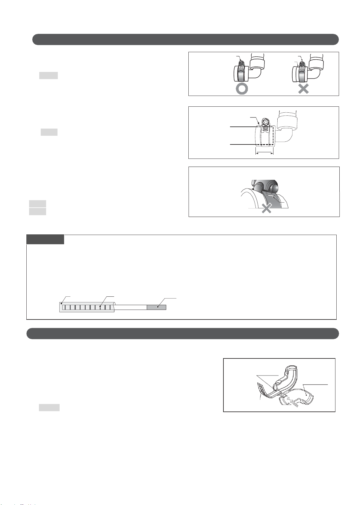
2. Connection of the joint:
Connect both the equipment side and the piping side to the joint by [Hose Band Connection].
(1) Make sure that the hose band is attached to the center of
ditch on the joint. (Figure 2-1)
NOTE : If the hose band is not installed at the correct
position, water may leak.
(2) Insert the connection pipe to the back of the joint (30mm).
(Figure 2-2)
NOTE : If the hose band is tightened without inserting
the pipe to the back, water may leak
(3)After the pipe is inserted, tighten the hose band
with a screwdriver. (Approximate torque 400N·cm)
(Figure. 2-3)
※Fig. 2-3 shows the case that the tightening is loose.
NOTE : If the hose band is not enough tightened, water may leak.
NOTE : If the hose band is overtightened, it may cause damage.
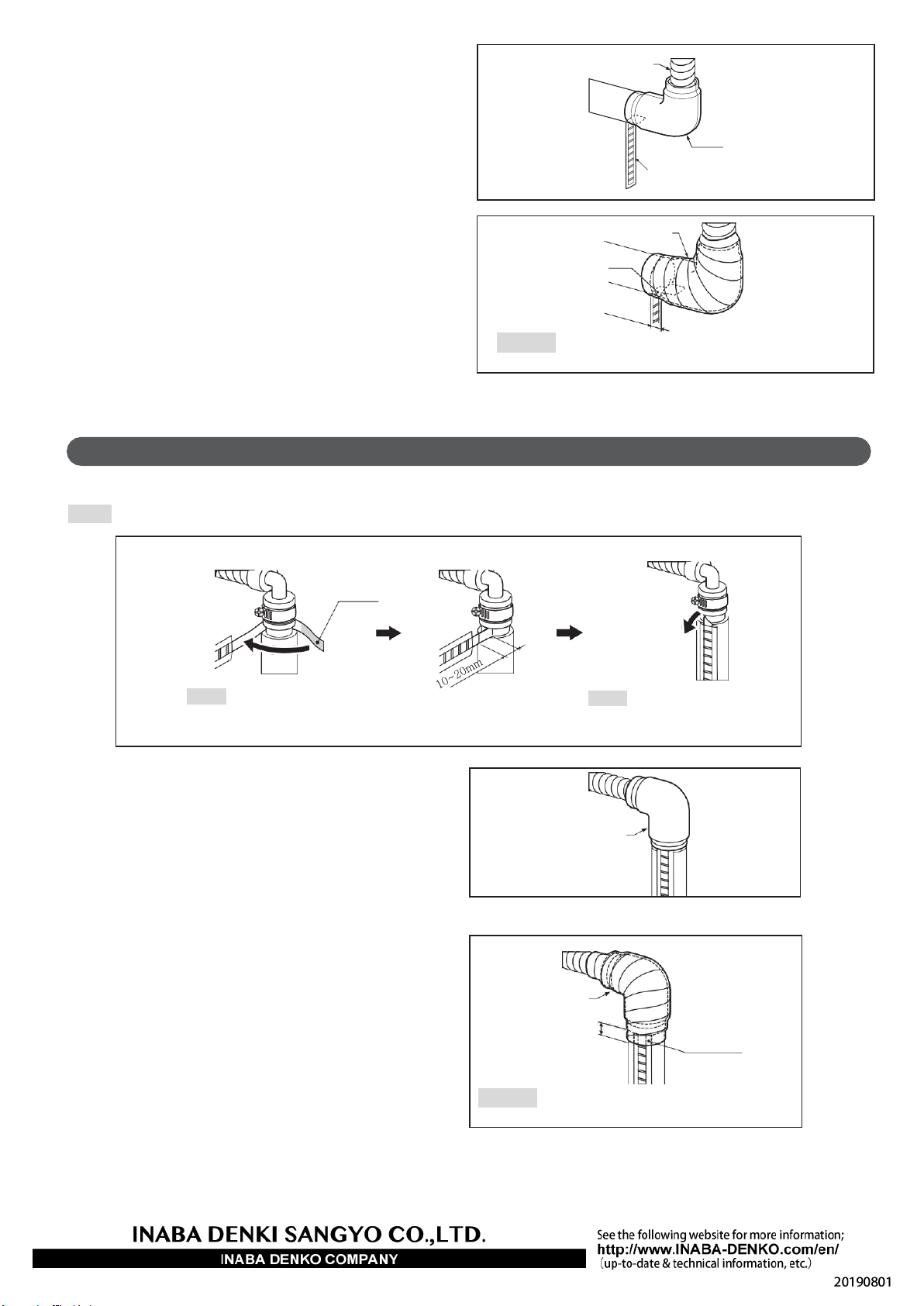
3. Setting of water leakage detection sheet and installation of insulation cover:
Request
Before mounting the water leakage detection sheet
●Use this sheet only for the water flow test of the enclosed drain hose.
●Do not remove the inspection bag. Be sure to carry out the work with a bag attached.
●If water droplets or perspiration adhere to the water leakage detection sheet, the blue line may
disappear. Handle the product carefully during installation.
●If the water leakage detection sheet is left in a humid condition for a long time, the blue line may disappear.
For this reason, immediately perform the installation and the water flow test after opening the seal.
(1) Set the water leakage detection sheet to the insulation cover.
<Set to elbow insulation cover>
Make sure that the inspection bag of the water leakage detection sheet
enters 0 to 20 mm from the end of the insulation cover with the blue line
downward. (Figure 3-1)
Remove the release paper from the water leakage detection sheet and
attach it to the insulation cover.
Caution : If the inspection bag is inserted to the insulation cover too
deeply (more than 20m), it may be undetectable
30mm
(Figure 2-1)
Hose
band
Be located in the center of ditch.
Come out from the ditch.
Ditch of
hose band
Hose band
Request
Joint
Pipe
More than two holes visible.
Perforated
hole
Inspection bag
Blue line
Release paper (adhesive surface)
(Figure 3-1)
Inspection bag
Blue line downward
Elbow
insulation
cover

-4-
【Setting to vertical piping】
(2) Install an insulation cover to the joint. (Figure 3-2)
(3) Wind PVC tape making no gaps between the pipe and
the insulation cover. (Figure 3-3)
(4) Confirmation after installation
Check if the blue line of the water leakage detection sheet has not disappeared more than two hours after the
start of water flow. After confirming the blue line has not disappeared, cut the base of the leak detection sheet
with scissors avoiding damage to the insulation part.
(1) Set the water leakage detection sheet to the connection pipe. (Figure 3-4)
NOTE : If insulation is attached to the connection pipe, remove the insulation and attach the sheet to the inside VP pipe.
(2) Install an insulation cover to the fitting. (Figure 3-5)
(3)Wind PVC tape making no gaps between the pipe and
the insulation cover. (Figure 3-6)
(4) Check after installation:
Check if the blue line of the water leakage detection sheet has not disappeared more than two hours after the
start of water flow. After confirming the blue line has not disappeared, cut the base of the leak detection sheet
with scissors avoiding damage to the insulation part.
(Figure 3-2.)
Insulated drain hose
Place the detection sheet directly
below the insulation cover.
Insulation cover
(Figure 3-3)
PVC tape wind
Inspection bag
10mm or more
NOTE : When attaching the adhesive
surfaces, do not involve the
inspection bag.
Adhesive surface
(Figure 3-4)
NOTE : Bend with the blue line
to be visible.
(Figure 3-5)
Insulation cover
PVC tape winding
(Figure 3-6)
Inspection bag
Caution Wind the PVC tape overlapping the inspection bag
by 10mm or more.
Caution Wind the PVC tape overlapping
the inspection bag by 10mm or more.
10mm or more
This manual suits for next models
1
Other INABA DENKO Air Conditioner Accessories manuals
Popular Air Conditioner Accessories manuals by other brands

Artrom
Artrom ARM-12DCWF user manual

Carrier
Carrier 52S Wall Thermostat Interface Retrofit Kit installation instructions

Mitsubishi Electric
Mitsubishi Electric PAC-SK38HR-R manual

Trane
Trane BAYCOVR112 Installer's guide

Mitsubishi Electric
Mitsubishi Electric CMY-Q100CBK installation manual

Samsung
Samsung ASSY MIM-H04UN User & installation manual