© American Time
2
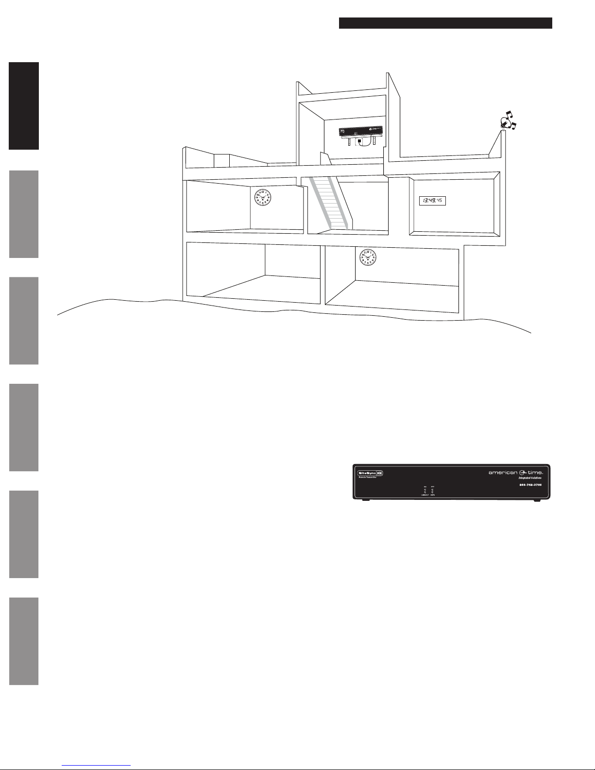
Wireless Remote Transmitter Installation Manual
The SiteSync IQ Remote Transmitter is furnished with a wireless transmitter. In the USA, these Radio Frequency (RF) transmitters operate
in the licensed UHF business band at 450 to 470 MHz. The SiteSync IQ Remote Transmitter needs to be licensed. For USA customers,
American Time offers the use of a shared nationwide FCC license, call sign WQFW336. In the USA and its territories, this allows nationwide
wireless system operation on the following 5 frequencies up to 100 watts of power, except near the Canadian border*:
464.600 MHz 464.625 MHz 464.650 MHz 464.675 MHz 464.700 MHz
If you wish to use an existing license in the 450-470 MHz band, or obtain a xed license for your site, please contact American Time at 866-
748-3796.
*This shared nationwide license is limited to 5 watts power North of Line A and East of Line C, as dened by a treaty with Canada. Please
check the FCC label on the back of your remote transmitter to determine the 5W transmitter FCC ID.
FCC Conformity (USA only)
Safety Precautions
FCC Licensing
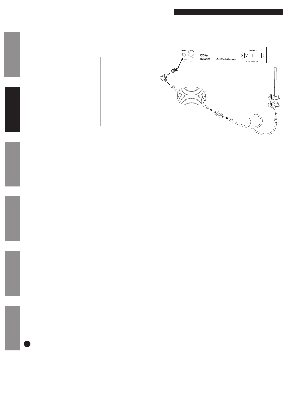
All electrical power and signal wiring connected to the SiteSync IQ Remote Transmitter, secondary clocks, signaling devices and antennas
must be installed by qualied persons in conformance with applicable national and local electrical codes. Improper installation of this
equipment can result in lethal electrical shock and re.
The SiteSync IQ Remote Transmitter should be installed in a secure location protected from:
• Physical damage
• Water, including condensation
• Direct sunlight
• Operation by untrained personnel
Injury From Radio Frequency Transmissions: Do not operate the SiteSync IQ Remote Transmitter when somebody is either touching the
transmitting antenna or standing within 2-3 ft. (60-90 cm) of it, to avoid the possibility of radio frequency burns or related physical injury. Do
not allow children to operate or play with or near the transmitting equipment.
Dynamite Blasting Caps: Operating the SiteSync IQ Remote Transmitter within 500 ft. (150 m) of dynamite blasting caps may cause them
to explode. Turn OFF these units when in an area where blasting is in progress.
FCC Warning: This equipment may generate or use radio frequency energy. Changes or modications to this equipment may cause harmful
interference unless the modications are expressly approved in the instruction manual. The user could lose the authority to operate this
equipment if an unauthorized change or modication is made.
The above warning list is not intended to include all hazards that may be encountered when using this equipment.
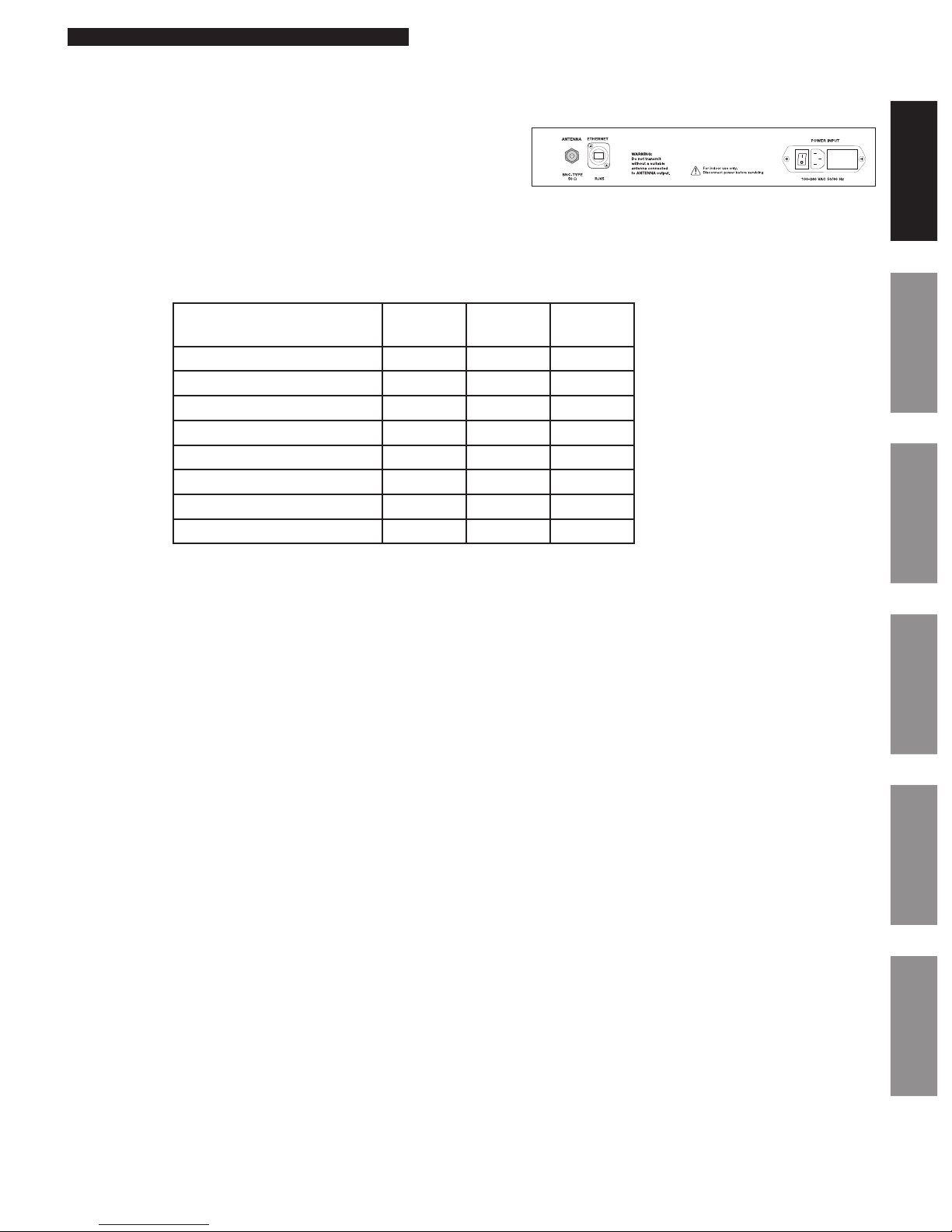
SiteSync IQ Equipment Transmitter FCC ID Industry Canada
Transmitter ID
Industry Canada
Receiver ID
Remote Transmitter 5 & 10W AIERIT33-46009 1084A-RIT3346009 8306A-SSIQ
Remote Transmitter 25 & 40W ABZ99FT4048 109AB-99FT4048 8306A-SSIQ
Secondary Wall Clocks N/A N/A 8306A-SSIQ
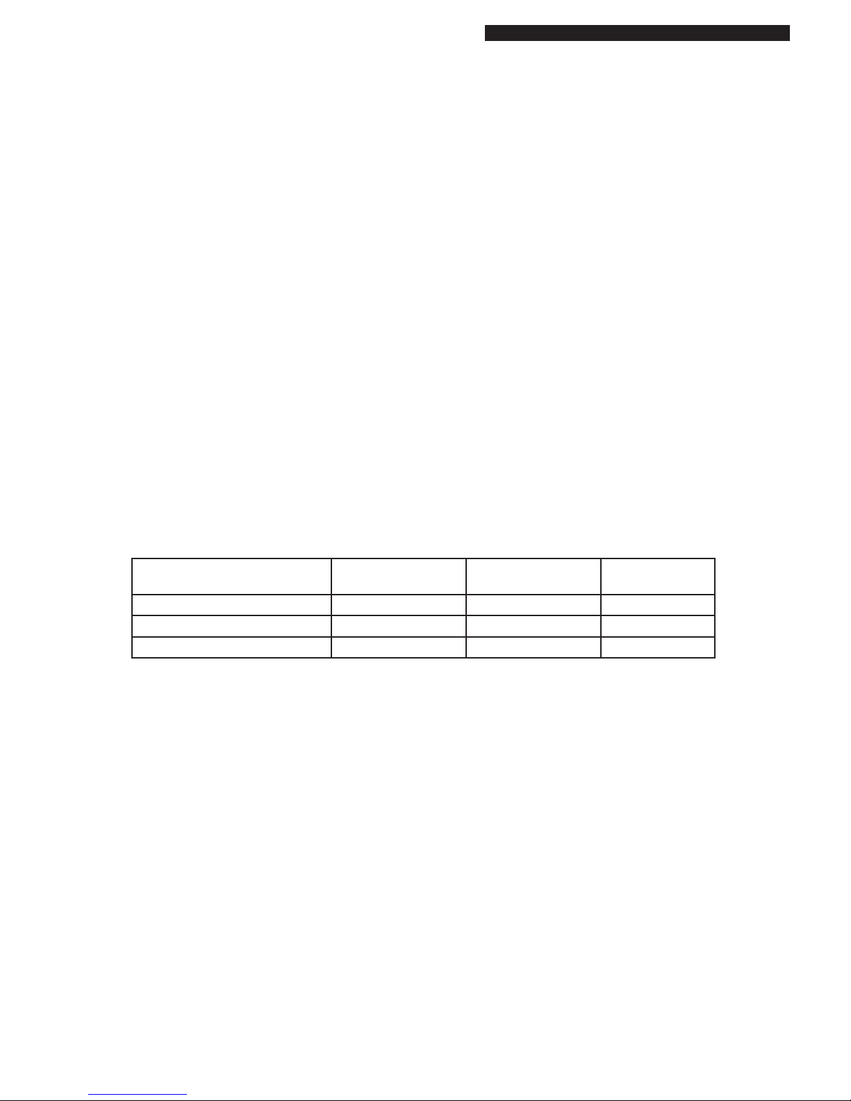
FCC and Industry Canada Approvals
Changes or modications not expressly approved by American Time could void the user's authority to operate the equipment.
Responsible Party: American Time, 140 3rd St. S., PO Box 707, Dassel, MN 55325-0707 USA
TEL: 320-275-2101, declares that the product(s):
SiteSync IQ Remote Transmitter and Analog Clocks
Comply with Part 15 of the FCC Rules. Operation is subject to the following two conditions:
(1) This device may not cause harmful interference
(2) This device must accept any interference received, including interference that may cause undesired operation
This equipment has been tested and found to comply with the limits for a Class B digital device, pursuant to Part 15 of the FCC Rules. These
limits are designed to provide reasonable protection against harmful interference in a residential installation. This equipment generates,
uses and can radiate radio frequency energy and, if not installed and used in accordance with the instructions, may cause harmful
interference to radio communications. However, there is no guarantee that interference will not occur in a particular installation. If this
equipment does cause harmful interference to radio or television reception, which can be determined by turning the equipment off and on,
the user is encouraged to try to correct the interference by one or more of the following measures:
• Reorient or relocate the receiving antenna
• Increase the separation between the equipment and receiver
• Connect the equipment into an outlet on a circuit different from that to which the receiver is connected
• Call the dealer or an experienced radio/TV technician for help