American Torch Tip T-300 User manual

www.americantorchtip.com
RATING:
300A C02 225A MIXED GAS
@ 100% DUTY CYCLE
.023” 0.6mm TO 5/64” 2.0mm WIRE

www.americantorchtip.com
MIG Gun Part Numbering System 300 AMP
Gun Assembly - Front
102
Connector Assy
122F
122M
Post &
Screws
83E
Handle
92E
Switch
152-T
Hanger
63-7902
Clamp
142-6TS
Support
ATW300
Unicable
244-T
63J-45
63J-60
Conductor
Tube
Gas Hose
Nipple
64N
Terminal
AT310 - 35
Length
10 = 10 ft
12 = 12 ft
15 = 15 ft
20 = 20 ft
25 = 25 ft
Gun Amperage
3 = 300 amp
23 - .023
30 - .030
35 - .035
40 - .040
45 - .045
52 - .052
116- 1/16
Wire Size
Plugs
AT = Tweco
ALN
=
Lincoln
AX
= Euro
AM
= Miller
Special Part Numbering System
AT310 - 35 - X
Special Set Up
If Required
Nozzle
Slip-On
54A
Gas Diuser
See # 4
Contact Tips
34CT
Nozzle Insulator
34A
Nozzle
Insulator
See # 3
See # 2
Nozzle
Self Insulated
See # 1
Nozzle
Coarse Thread

www.americantorchtip.com
No. Part No. Description
124CT-37-S Nozzle, Coarse Thread, 3/8” I.D.
24CT-50-S Nozzle, Coarse Thread, 1/2” I.D.
24CT-62-S Nozzle, Coarse Thread, 5/8” I.D.
24CT-75-S Nozzle, Coarse Thread, 3/4” I.D.
No. Part No. Description
414-23 Contact Tip .023” 0.6mm
14-30 Contact Tip .030” 0.8mm
14-35 Contact Tip .035” 0.9mm
14-40 Contact Tip .040” 1.0mm
14-45 Contact Tip .045” 1.2mm
14-52 Contact Tip .052” 1.3mm
14-116 Contact Tip .062” 1.5mm
No. Part No. Description
544-3545-15 Liner Assy., 15’ .035-.045”
44-116-15 Liner Assy., 15’ .062”
44-564-15 Liner Assy., 15’ 5/64”
44-3545-25 Liner Assy., 25’ .035-.045”
44-116-25 Liner Assy., 25’ .062”
44-564-25 Liner Assy., 25’ 5/64”
44N-3545-1 Nylon Liner Assy., 15’ .035-.045”
44N-116-15 Nylon Liner Assy., 15’ .062”
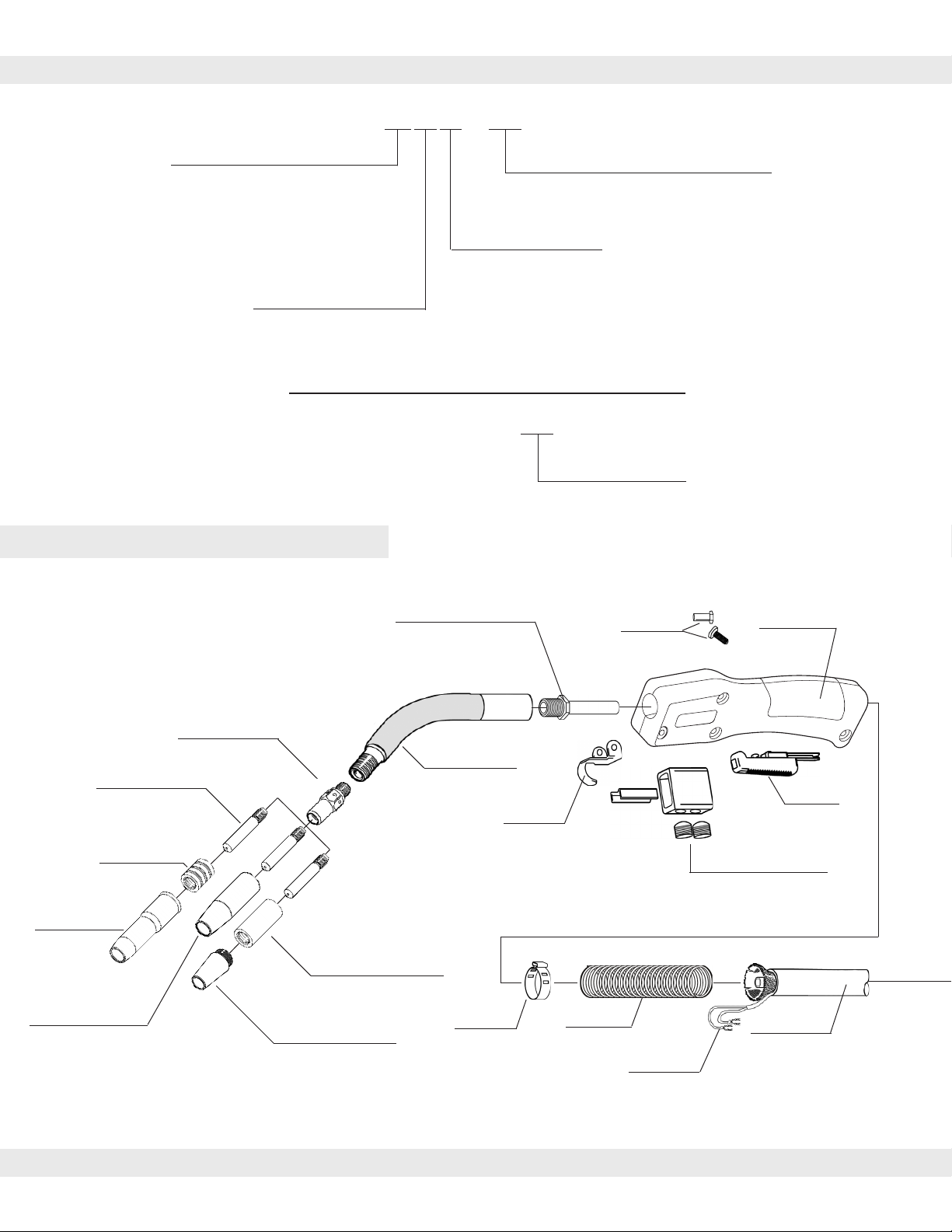
Gun Assembly - Rear
No. Part No. Description
223-37 Nozzle, Self Insulated, 3/8” I.D.
23-50 Nozzle, Self Insulated, 1/2” I.D.
*23-62 Nozzle, Self Insulated, 5/8” I.D.
23-75 Nozzle, Self Insulated, 3/4” I.D.
23T-37 Nozzle, Tapered Self Ins. 3/8” I.D.
324A-50 Nozzle, Adjustable, 1/2” I.D.
24A-62 Nozzle, Adjustable, 5/8” I.D.
24A-75 Nozzle, Adjustable, 3/4” I.D.
24A-37-SS Nozzle, Short Stop, 3/8” I.D.
24A-50-SS Nozzle, Short Stop, 1/2” I.D.
24A-62-SS Nozzle, Short Stop, 5/8” I.D.
* Standard Nozzle with gun
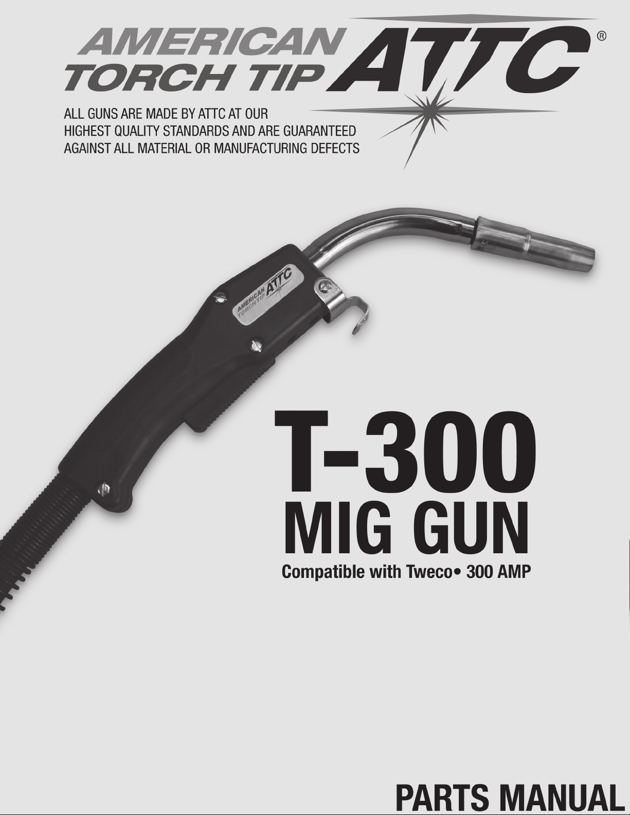
Cone Nut Connector Cone
Power Pin
Mount
Pin (Lincoln)
Pin (Tweco #4)
Conduit Liner
Power Pin O-Ring
64-8202 STD O-Ring
64-8309 Miller O-Ring
Liner Set Screw
64-8203
63-6302 63-6301
64-8208
See Chart for Part #’s
64-8211T
Pin (Miller)
64-8311T
64-8411T
Liner O-ring
64-9001
Guide Cap
64-8303 (.035-1/16)
64-8304 (5/64-3/32)
Unicable Assembly Spring Guard
See Chart for Part #’s
Control Plug
Connector
64-7909
63-6502
Mounting Screw
64-6501
Housing & Screws
63-6101
Outer Jacket
Clamp
63-7902
Handle
64-6106
Lead Extension Lead Extension
64-8404 (Spade) 64-8306 (Miller)
64-8403 (Lincoln)

1. Poor Wire Feed
• Conduit liner clogged or kinked
• Incorrect liner size or contact tip
• Line cut too short and not seating properly in gas diffuser
• Drive rolls too tight resulting in scoring of welding wire
• Welding wire dirty, rusty and/or too much cast
2. Short Tip Life
• Drive rolls too tight resulting in scoring of the welding
wire
• Welding wire dirty, rusty and/or too much cast
• Uncoated wire being used, increasing usage
• Wrong tip size
• Over torch rated duty cycle
• Loose contact tip and/or retaining head
3. Gun Overheating
• Loose retaining screw on quick connect block
• Insufcient gauge power cable and/or ground cable
• Loose connector cone and/or cone nut
• Gun being run beyond its amperage range
• Electrical malfunction in power source
4. Switch Malfunctioning
• Bad connection of leads to switch terminals
• Spatter built up between lever and switch housing
• Contacts dirty in switch
• Switch housing screws loose
• Broken or worn switch lead
5. Weld Porosity
• Spatter built up in nozzle blocking gas
• Leaks in gas hose or improper connection
• O-rings on power pin are cut or damaged
• Inner tube loose from connector cone
• Improper shielding gas or welding wire
• Rusty or poor quality welding wire
• Parent metal rusty or contaminated or high in Sulfur
content
• Flow improperly set
6. Contact Tip Burn Back
• Improper voltage and/or wire feed speed
• Erratic wire feeding
• Improper tip stick-out
• Improper electrode stick-out
• Faulty ground
7. Erratic Arc
• Worn contact tip
• Buildup inside of line
• Wrong tip size
• Not enough bend in neck
8. Extreme Spatter
• Improper machine parameters
• Improper tip installation
• Improper tip shielding
• Contaminated wire or work piece
1. Disconnect all power before servicing or changing welding gun components. Failure to disconnect power can
lead to dangerous electrical shock which can kill.
2. Smoke, fumes and gases can be dangerous to your health. Keep smoke, fumes and gases from the breathing
area. Fumes from welding are of various types and strengths, depending on the kind of base metal being welded.
3. Arc welding produces dangerous light radiation. Adequate eye protection must be worn.
4. All exposed skin must be covered with ame resistant, protective clothing. Do not wear clothing made from
ammable synthetic bers.
5. Protective screens or barriers should be used to protect others from spatter, ash and glare while welding.
GENERAL SAFETY
TROUBLESHOOTING
AMERICAN TORCH TIP CO.
1.800.342.8477
INT’L PH . 941.753.7557
FAX: 941.753.6917
WEBSITE: www.americantorchtip.com
CONTACT US
The Family of MIG Guns
Large Curve MIG Gun Robotic MIG Gun Small Curve MIG Gun Semi-Auto MIG Gun Automatic MIG Gun
This manual suits for next models
2