manuals.online logo
Brands
  1. Home
  2. •
  3. Brands
  4. •
  5. Weller
  6. •
  7. Soldering Gun
  8. •
  9. Weller EC2002M User manual

Weller EC2002M User manual

1
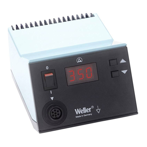
MODEL EC2002M ELECTRONIC SOLDERING STATION
WARNING: This product, when used for soldering and similar applications, produces chemicals known to the State of
California to cause cancer and birth defects or other reproductive harm.
OPERATING INSTRUCTIONS
Unpack unit carefully. Place spring and funnel in slot in top of tool stand. Attach tool stand to either side of power unit, if desired.
Fill reservoir with water and wet sponge, distilled water is preferred. Insert tool in holder and connect tool plug to receptacle on
power unit; rotate plug housing to lock plug into receptacle. Insert line cord plug into properly grounded AC receptacle and turn
station on. When the tip temperature reaches 400°F (204°C), remove tool from holder and tin tip with solder. Unit will be ready for
use when it reaches the set point temperature.
The unit display shows a Read mode by default which displays the current temperature of the tip. To switch into the Set mode,
turn the knob slightly and the display will show the current set temperature. Release the knob when you have reached the desired
temperature setting, and after a three second delay the display will switch back into Read mode. When you first turn the unit on,
the display should show 888 for two seconds as a test and then will display the Set temperature for three seconds before
switching into Read mode.
Always use the lowest temperature that will handle the load you are soldering. The Weller®electronic control provides maximum
power to the heated load even when set to the lowest temperature; therefore, there is no need to use high temperature to handle
heavy soldering loads. By using lower temperatures and properly selecting tip styles, sensitive components will be protected from
heat damage.
While the unit is in the Read mode, the displayed tip temperature may fluctuate. This fluctuation is normal and represents the
control system response to the changing load. Tip selection for a particular job may be optimized by observing the tip temperature
fluctuations during the soldering operation. Normally, the tip should be selected for minimum fluctuation. This will provide the
shortest soldering dwell time; however, some applications may require a fast response with total fluctuation not critical.
A WCM1 Calibration Unit is available that interfaces directly with the EC2002Ms microprocessor through the iron receptacle and
provides the ability to enable a timed setback mode, a temperature lock out feature, a switch to change the display measurement
between °F and °C, digital calibration of the unit to an outside temperature reference, and reset the unit to its original factory
calibration. When the unit enters Setback mode, the unit display will highlight the bottom segment of all three digits. Turn the unit
off and back on to return to normal operation. If the unit is locked to a specific temperature, this temperature may be checked, but
not altered, by turning the knob.
WARNING: Do not remove ground prong from line cord plug. Removal may cause tip temperature to be erratic.
CALIBRATION
The EC1201A, EC1302B and EC1503B soldering tools use high precision platinum RTD temperature sensors; therefore, they are
interchangeable without any re-calibration. Should you wish to custom calibrate your EC2002M unit, this can be easily accomplished
with the use of a WCM1 Calibration Unit and a temperature measurement device like the WA2000.
AVAILABLE MODELS AND HAND PIECES
Product Description
EC2002M-0 Power unit only, 120V 60Hz, °F display
EC2002M-0D Power unit only, 240V 50/60Hz, °C display
EC2002M-1 Power unit, 120V 60Hz, °F display, EC1201A tool with ETA tip
EC2002M-1D Power unit, 240V 50/60Hz, °C display, EC1201A tool with ETA tip
EC2002M-2 Power unit, 120V 60Hz, °F display, EC1302B tool with EPH101 tip
EC2002M-2D Power unit, 240V 50/60Hz, °C display, EC1302B tool with EPH101 tip
EC2002M-3 Power unit, 120V 60Hz, °F display, EC1503B tool with EMA tip
EC2002M-3D Power unit, 240V 50/60Hz, °C display, EC1503B tool with EMA tip
EC1201A 40 Watt soldering tool w/ETA tip
EC1302B 20 Watt soldering tool w/EPH101 tip
EC1503B 42 Watt high capacity soldering tool w/EMA tip
SPECIFICATIONS
1. Power input: 120VAC ±10%, 60 Hz, (240VAC ±10%, 50/60 Hz). 60 watts
2. Power unit output voltage: isolated 24VAC @ 2.7 amperes.
3. Size: 4.5 x 5.9 x 3.6
4. Line Cord: 3 wire, U.L. recognized
5. Tip temperature control range: 350°F to 850°F (177°C to 454°C).
6. Control setting resolution: 1°F (1°C).
7. Stability: ±10°F (±6°C) per Mil-Std-2000.
8. Absolute accuracy: Average tip temperature is calibrated to ±9°F (±5°C) at idle with no load.
9. Ambient temperature range: 60°F to 110°F (16°C to 44°C).
10. Housing made with Electrostatic Protective Material as required in MIL-B-81705.
11. Housing passes Static Decay test per Federal Test Method Std. No. 101, Method 4046.
12. Weller®ESD tools comply with DOD-HDBK-263.
13. EC2002 units are U.L. listed and meet DOD-STD-2000, MIL-STD-2000, MIL-S-45743, W-S-6536,W-S-570, DOD-STD-
1686.
TROUBLESHOOTING GUIDE
WARNING:AC LINE VOLTAGE IS PRESENT INSIDE POWER UNIT EVEN WHEN POWER SWITCH IS OFF.
REFER SERVICE TO QUALIFIED PERSONNEL.
NOTE: Access to internal parts may be gained by removing four rubber feet, four bottom screws and
top case.
2
Check wiring from tool receptacle to printed circuit board.
 Repair or replace if defective.
Replace soldering tool with known good tool and recheck.
 Troubleshoot soldering tool using guide in soldering iron tech sheet.
TOOL OVERHEATING
Replace soldering tool with known good tool and recheck.
 Troubleshoot soldering tool using guide in soldering iron tech sheet.
Replace printed circuit board assembly in station.
TOOL DOES NOT HEAT  DISPLAY NOT LIT
With line cord unplugged and power switch on, check for about 21 ohms at line cord blades for 120VAC units (55 ohms for
240VAC unit).
 Check fuse, located on bottom of case  replace if required. Use slow blow fuse  0.6A for 120VAC (0.3A for 240VAC).
 Check power switch  replace if defective.
 Check line cord  repair or replace if defective.
 Check transformer primary  replace transformer if defective.
With line cord plugged in and power switch on, check for 24VAC ±10% between pins #1 and #4 of tool receptacle.
 Check transformer secondary for 24VAC ±10% - replace transformer if defective.
 Check wiring to printed circuit board assembly  repair or replace if defective.
 Replace printed circuit board assembly.
With line cord plugged in and power switch on, check for 5 VDC ±1 VDC, between pins #3 and #4 of tool receptacle.
 Replace printed circuit board assembly.
TOOL DOES NOT HEAT  DISPLAY LIT
3
TIP TEMPERATURE TESTING ERRORS
NOTE: Tip temperature testing must be done using 30 gauge thermocouple wire resistance welded to the center of the
wetted area on the tip, tinning should be removed before welding. Other methods of measurements, or heavier gauge thermo-
couple wire, will cause errors. Thermocoupled tip temperature test kits are available; see Replacement Parts and Accessories
Section.
Replace soldering tool with known good tool and recheck tip temperature.
 Troubleshoot soldering tool using guide in soldering iron tech sheet.
Calibrate station using WCM1 Calibration Unit. Instructions are in Calibration Unit tech sheet.
Calibrate tip temperature using WCM1 Calibration Unit; especially if a category B or C tip is used (see Tip and Tool Selection Sheet
for category of tip). Instructions are in Calibration Unit Tech Sheet.
DISPLAY PROBLEMS
Missing segments or digits.
 Replace printed circuit board assembly
Display reading unsteady.
 Check that line cord is properly grounded.
 Check for low line voltage.
 Check AC line for excessive noise.
 Replace soldering tool with known good tool and recheck tip temperature.
 Check tool for defects using guide in soldering iron tech sheet.
HIGH TIP VOLTAGE
Replace soldering tool with known good tool and recheck tip voltage.
 Troubleshoot soldering tool using guide in soldering iron tech sheet.
Check for continuity from pin #5 of tool receptacle to line cord ground pin.
 Check wiring from tool receptacle to line cord ground pin - repair if defective.
CUSTOMER SERVICE
Should you EC2002M require service, it may be sent to the following address:
USA
Cooper Tools - Weller Division
1000 Lufkin Road
Apex, NC 27539
Attn: Repair Department
FAX: 919-387-2640
Phone: 1-800-476-3030
CANADA
Cooper Tools
164 Innisfil Street
Barrie, Ontario, Canada L4N 3E7
Attn: Repairs
FAX: 1-800-403-TOOL (8665)
Phone: 705-728-5564 Ext. 2026
4
REPLACEMENT PARTS AND ACCESSORIES
KEY NO. PART NO. DESCRIPTION
1 SW110 Power Switch
2 EC270 Receptacle and Wire Harness
3 EC271 Circuit Board Assembly
4 TR234 Power Transformer, 120VAC, EC2002M-0
5 FP3 Fuse, 0.6 AMP Slo Blo
Not Shown TC205 Sponge
Not Shown DS200K Desoldering Adapter Kit
Not Shown TC204 Spring and Funnel for EC1201A Tool
Not Shown IHF225EC Spring and Funnel for EC1302B Tool
Not Shown EC254 Spring and Funnel for EC1503B Tool
Not Shown EC1201AP EC1201A Tool with Stand
Not Shown EC1302AP EC1302B Tool with Stand
Not Shown EC1503AP EC1503B Tool with Stand
Not Shown SF60 Tool Funnel for SMT Tips
Not Shown SMTA Surface Mount Tip Adapter for EC1201A Tool
Not Shown WA2000 Soldering Tool Analyzer
Not Shown WCM1 Calibration Unit
Not Shown WPB1 Weller®Polishing Bar
Not Shown K111 Temperature Test Kit for EC1201A Tool
Not Shown K121 Temperature Test Kit for EC1302B Tool
Not Shown K131 Temperature Test Kit for EC1503B Tool
Assembly Schematic

Other Weller Soldering Gun manuals

Weller WSP 80 User manual

Weller

Weller WSP 80 User manual

Weller PUD 81R User manual

Weller

Weller PUD 81R User manual

Weller wsd 81 User manual

Weller

Weller wsd 81 User manual

Weller PH 70 User manual

Weller

Weller PH 70 User manual

Weller WTCP-S User manual

Weller

Weller WTCP-S User manual

Weller WX1012 User manual

Weller

Weller WX1012 User manual

Weller WSD 81i User manual

Weller

Weller WSD 81i User manual

Weller wd 2 User manual

Weller

Weller wd 2 User manual

Weller wecp-20 User manual

Weller

Weller wecp-20 User manual

Weller whs 40d User manual

Weller

Weller whs 40d User manual

Weller WXP?65 User manual

Weller

Weller WXP?65 User manual

Weller WT 2M User manual

Weller

Weller WT 2M User manual

Weller PYROPEN Piezo User manual

Weller

Weller PYROPEN Piezo User manual

Weller WD1 User manual

Weller

Weller WD1 User manual

Weller WR 2 User manual

Weller

Weller WR 2 User manual

Weller WESD51 User manual

Weller

Weller WESD51 User manual

Weller WXP 120 User manual

Weller

Weller WXP 120 User manual

Weller WPS18MP Pro Series User manual

Weller

Weller WPS18MP Pro Series User manual

Weller WSD 130 User manual

Weller

Weller WSD 130 User manual

Weller wsd 81 User manual

Weller

Weller wsd 81 User manual

Weller D550 Series User manual

Weller

Weller D550 Series User manual

Weller WLIR30 User manual

Weller

Weller WLIR30 User manual

Weller wsd 161 User manual

Weller

Weller wsd 161 User manual

Weller HAP 1 User manual

Weller

Weller HAP 1 User manual

Popular Soldering Gun manuals by other brands

ELCART 07/00735-00 user manual

ELCART

ELCART 07/00735-00 user manual

Analog Technologies ATAS80 Instructional manual

Analog Technologies

Analog Technologies ATAS80 Instructional manual

Hakko Electronics FX-889 instruction manual

Hakko Electronics

Hakko Electronics FX-889 instruction manual

jbc ATS instruction manual

jbc

jbc ATS instruction manual

Monacor SIC-520ROHS instruction manual

Monacor

Monacor SIC-520ROHS instruction manual

Parkside PLS 48 A1 Operation and safety notes

Parkside

Parkside PLS 48 A1 Operation and safety notes

Parkside PLS 48 B1 Operation and safety notes

Parkside

Parkside PLS 48 B1 Operation and safety notes

Kemper 1610 manual

Kemper

Kemper 1610 manual

jbc BT-2BQA instruction manual

jbc

jbc BT-2BQA instruction manual

Kurtz Ersa i-CON VARIO 2 operating instructions

Kurtz Ersa

Kurtz Ersa i-CON VARIO 2 operating instructions

jbc CD-SE manual

jbc

jbc CD-SE manual

Hakko Electronics FX-952 instruction manual

Hakko Electronics

Hakko Electronics FX-952 instruction manual

Conrad Electronic ST50-D 50W operating instructions

Conrad Electronic

Conrad Electronic ST50-D 50W operating instructions

Pace HW 100 HeatWise Operation and maintenance manual

Pace

Pace HW 100 HeatWise Operation and maintenance manual

Roller Jet-Fire instruction manual

Roller

Roller Jet-Fire instruction manual

jbc B-iRON 210 instruction manual

jbc

jbc B-iRON 210 instruction manual

UCL SWIFT KR12A user manual

UCL SWIFT

UCL SWIFT KR12A user manual

Metcal MX-500P user guide

Metcal

Metcal MX-500P user guide

manuals.online logo
manuals.online logoBrands
  • About & Mission
  • Contact us
  • Privacy Policy
  • Terms and Conditions

Copyright 2025 Manuals.Online. All Rights Reserved.