AMERICANA PERGOLA User manual

Recommended Tools:
Before You Begin:
Note on Masonry Units:
Note on Electric Drills:
Note on Cutting and Drilling:
Saftey Glasses, Tape Measure, Carpenters Level, Framing Square, Hex Head Nut Drivers,
Chal Line, Electric Drill w/ Bits, Pliers, Metal Hac Saw, Silicone Caul ing,
Regular and Phillips Screw Drivers
1) Please read all instructions and notes carefully. Chec the Parts List or Bill of Materials for
any missing parts and gather necessary tools. To prevent scratching of painted materials,
place on a tarp, paper, or other protective material.
2) You may be required to obtain a building permit for this structure from your local building
authority. Contact your local building department for details.
3) Note that this shade structure is not designed to carry additional loads such as hanging
heavy plants, swings, people, or other objects.
If securing to stone, concrete, or other masonry unit, a masonry drill and bits may be required.
You may also be required to purchase masonry anchor bolts, as the 1-1/2" lag screws
provided will not be sufficient.
We recommend lowering the speed of your drill during this installation. Installing Te screws
at a high rpm may cause the Te screws to become damaged or brea during installation.
Cutting and drilling will cause metal shavings. These shavings must be carefully removed by
sweeping or brushing. If this is not done, the metal shavings will quic ly rust and stain the
surface finish.
If you have any questions during installation, please call us at 1-800-851-0865 Rev. - 5/04/10
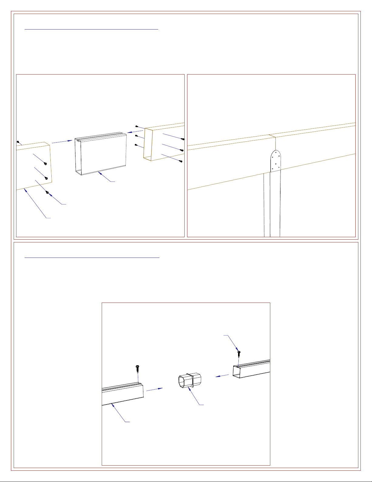
ATTACHED
SINGLE HEADER PERGOLA
ASSEMBLY INSTRUCTIONS

1. 3" x 3" Post 2. 3" x 8" Header 3. 2" x 6" Rafter 4. 1.5" x 1.5" Lattice
8. Post Top Bracket
(Optio al)
13. Post Side Plate
(Foam Filled) (Optio al)
5. Post Mou ti g Bracket
10. Rafter Mou ti g Bracket9. Rafter Ha gi g Bracket
14. 5/8" Hole Plug
(Optio al)
15. Colum Wrap Kit
(Square Show ) (Optio al)
18. #12 x 1 1/4" HWH
#5 Tek Screw17. Lag Screw I sert
20. #10 x 2" Stai less Steel
Sheet Metal Screw (SMS)
16. 1/4" x 1 1/2" Lag Screw
19. #8 x 3/4" HWH
#2 Tek Screw
6. Heavy-Duty Post
Mou ti g Bracket (Optio al)
11. Header Splice
(Optio al)
7. Post Top Bracket
(Sta dard)
12. Lattice Splice
(Optio al)
SINGLE HEADER PERGOLA
PARTS LIST
Co tact us at:
1-800-851-0865 or
www.america a.com

Fig. S-1
-If the header is in two or more pieces, insert an equal amount of the provided header splice into each of the square ends of the
headers and secure as shown using (12) 8 x 3/4" HWH 2 Tek Screws (see Fig. S-1).
-Be sure to place a post under the splice (see Fig. S-2).
-If the lattice is in two or more pieces, insert a lattice splice into the ends of two tubes and secure with (2) 8 x 3/4" HWH
2 Tek screws (see Fig. S-3).
HEADER SPLICE (OPTIONAL)
LATTICE SPLICE (OPTIONAL)
Fig. S-2
Fig. S-3
Lattice Splice
8 x 3/4" HWH 2 Tek Screw
Lattice Tube
Header Splice
8 x 3/4" HWH 2 Tek Screw
Header

-Determine the location for your pergola and mark the outer edges by snapping a chalk line the length of the headers along the
outer edge. Turn 90 degrees and snap a chalk line the length of your rafters beginning at the end of the previous chalk line.
Repeat to close the square.
-Locate the center of the posts by subtracting the desired overhang from the overall dimensions and snap four chalk lines
accordingly see Fig. 1-1). NOTE: If drawings were received with your order, use those as the guide.
NOTE: If installing fiberglass columns, skip to Step 4 now and return to this step later.
-Depending on the available surface or local building codes, there are three post mounting options.
Option 1 - If your pergola has the standard post mounting brackets, anchor them at the intersection of two centerlines by
drilling 4) 3/8" diameter holes and embedding 4) lag screw inserts. Then, attach the brackets to the surface using 4)
1/4" x 1 1/2" lag screws or appropriate anchors. Attach a post to each bracket using 4) #12 x 1 1/4" HWH #5 Tek screws
see Fig. 1-2).
Option 2 - If your pergola has the heavy duty mounting brackets, anchor them at the intersection of two centerlines by drilling
4) holes for anchor bolts not included, hole size will vary). Attach the bracket to the surface using 4) appropriate anchor
bolts. Attach a post to each bracket using 2) 3/8" x 3 1/2" bolts see Fig. 1-3). NOTE: If installing post side plates, only one
bolt is required for the post to bracket connection. Run the bolt the same direction the header will run.
Option 3 - If you plan to bury the posts, start by digging a hole approximately 12" diameter and 30" deep. Place rock 6" deep
in the bottom of the hole and drop the post in. Add or remove rocks as necessary to achieve the desired post height above
ground. Fill the hole with a pre-mix of cement, aggregate, and water. Check the post on all sides with a carpenters level to
make sure it is plumb. see Fig. 1-4). NOTE: Hole size and concrete mix must comply with local building codes.
STEP 1
Fig. 1-3
Fig. 1-1
Fig. 1-4
Fig. 1-2
24" Min.
Ground
Concrete
Rubble Stone
used to adjust
post height prior
to adding
concrete)
3" Sq. Post Option 3Option 2
Option 1
3" Sq. Post
Heavy Duty
Mounting Bracket
3/8" x 3 1/2" Bolt
w/ Nut Anchor Bolt
3" Sq. Post
1/4" x 1 1/2" Lag Screw
Conc. Anchor if Req'd) Lag Screw Insert
Not Req'd with
Anchor Bolts)
#12 x 1 1/4" HWH
#5 Tek Screw
Mounting Bracket
Centerline
of Posts
Outer Edge of Cover
Post
Structure

-Calculate Distance A using the formula shown in Fig. 2-1. Subtract one from the number of rafters and multiply that by the
center to center spacing of the rafters. Subtract that from the length of the header and divide by two.
XAMPL : You received a 10'-0" long header and five rafters. The standard rafter spacing is 24" on center.
5 - 1 = 4; 4 x 24 = 96; 120 - 96 = 24; 24 / 2 = 12; Therefore, Distance A = 12".
-Once you know Distance A for your project, position a rafter mounting bracket with Distance A between the end of the
header and the center of the bracket (see Fig. 2-1).
-Attach the bracket to the seam side of the header using (4) #8 x 3/4" HWH #2 Tek screws (see Fig. 2-2).
NOT : If the header is reinforced with a beam inside, #12 x 1 1/4" HWH #5 Tek screws must be used instead.
-Position the next rafter mounting bracket with the rafter spacing between the centers of the two brackets and attach as shown.
-Repeat for all rafter mounting brackets.
-Mark the proper location for the post top brackets by calculating Distance B as shown in Fig. 2-3. Be sure that the spacing
between the brackets attached to the header is equal to the spacing between the posts attached to the ground.
-If you received a column wrap kit with your pergola, attach the column plate to the header at the same location the post top
bracket will be attached using (4) #8 x 3/4" HWH #2 Tek screws as shown (see Fig. 2-4).
-If you received the standard post top bracket, attach each to the header at the proper locations using (12) #8 x 3/4" HWH
#2 Tek screws as shown (see Fig. 2-4a).
-If you received the optional post top bracket, attach each to the header at the proper locations using (4) #12 x 1 1/4" HWH
#5 Tek screws as shown (see Fig. 2-4b).
ST P 2
Fig. 2-3
Fig. 2-1 Fig. 2-2
Dist. A =
Dist. B =
Length of Header - [(# of Rafters - 1) x Rafter Spacing]
2
Length of Header - Post Spacing
2
Header
Rafter Mounting Bracket
#8 x 3/4" HWH
#2 Tek Screw
Rafter Mounting
Bracket
Header
Post Top Bracket
Rafter Mounting Bracket
Header
Post Top Bracket
Column Plate
(Only w/ Wrap Kit)
#8 x 3/4" HWH
#2 Tek Screws
#12 x 1 1/4" HWH
#5 Tek Screws
Fig. 2-4b
Fig. 2-4a
#8 x 3/4" HWH
#2 Tek Screws
Post Top
Bracket
Header
Header

-Hoist the header assembly to the top of the posts and insert the post top brackets into the top of each post (see Fig. 3-1).
-Secure the header assembly to each post using (4) 12 x 1 1/4" HWH 5 Tek screws per bracket (see Fig. 3-2).
NOTE: This applies to both post top bracket types.
-If your pergola has side plates, center two per post in front of the post along the header (see Fig. 4-1).
-Attach the inside face of the side plate to the post using 12 x 1 1/4" HWH 5 Tek screws through the pre-drilled holes.
-Also attach the side plate to the header at the top using (4) 12 x 1 1/4" HWH 5 Tek screws (see Fig. 4-2).
-Insert a hole plug into all exposed holes.
-Repeat for each side plate.
STEP 3
STEP 4 - OPTIONAL COLUMN KITS: SIDE PLATES
Fig. 4-1 Fig. 4-2
Fig. 3-1 Fig. 3-2
3" Sq. Post
Header Assembly
3" Sq. Post
12 x 1 1/4" HWH
5 Tek Screw
Header Assembly
Header Assembly
Side Plate
3" Sq. Post
Header
Assembly
Side Plate
12 x 1 1/4" HWH
5 Tek Screw
Hole Plug

-Snap two column sections together by fitting the tongues into the grooves and lightly tapping with the heel of your hand.
-Once two sets of sections are locked together, stand them on end and snap the open ends together around a post (see Fig. 4- ).
-Anchor the bottom of the column with two lower column brackets, (6) lag screw inserts, (6) 1/4" x 1 1/2" lag screws into the
surface, and (6) #8 x /4" HWH #2 Tek screws into the column (see Fig. 4-4).
-Once the column sections are secure, assemble a column cap around the bottom of the column.
-Attach the column cap to the column using (6) #8 x /4" HWH #2 Tek screws as shown (see Fig. 4-5).
-Assemble another column cap around the top of the column.
-Push the column cap up until flush with the bottom of the header and attach to the column plate using (4) #8 x /4" HWH
#2 Tek screws (see Fig. 4-6).
-Attach the column cap to the column using (6) #8 x /4" HWH #2 Tek screws as shown (see Fig. 4-6).
STEP 4 - OPTIONAL COLUMN KITS: SQUARE WRAP KIT
Fig. 4-5 Fig. 4-6
Fig. 4- Fig. 4-4
Column
Section
" Sq. Post
#8 x /4" HWH #2 Tek Screw
Lower Column Bracket
Lag Screw Insert
1/4" x 1 1/2" Lag Screw
Column
Column Cap
#8 x /4" HWH
#2 Tek Screw
Header Assembly
Column
Column Cap
Column Plate
#8 x /4"
HWH #2
Tek Screw
Column

-Snap two column sections together by fitting the tongues into the grooves and lightly tapping with the heel of your hand.
-Stand the sections on end and snap the open ends together around a post (see Fig. 4-7).
-Anchor the bottom of the column with three lower column brac ets, (3) lag screw inserts, (3) 1/4" x 1 1/2" lag screws into the
surface, and (3) #8 x 3/4" HWH #2 Te screws into the column (see Fig. 4-8).
-Once the column sections are secure, assemble a column cap around the bottom of the column.
-Attach the column cap to the column using (6) #8 x 3/4" HWH #2 Te screws as shown (see Fig. 4-9).
-Assemble another column cap around the top of the column.
-Push the column cap up until flush with the bottom of the header and attach to the column plate using (4) #8 x 3/4" HWH
#2 Te screws (see Fig. 4-10).
-Attach the column cap to the column using (6) #8 x 3/4" HWH #2 Te screws as shown (see Fig. 4-10).
STEP 4 - OPTIONAL COLUMN KITS: ROUND WRAP KIT
Fig. 4-9 Fig. 4-10
Fig. 4-7 Fig. 4-8
Column
Section
3" Sq. Post
#8 x 3/4" HWH #2 Te Screw
Lower Column Brac et
Lag Screw Insert
1/4" x 1 1/2" Lag Screw
Column
Column Cap
#8 x 3/4" HWH
#2 Te Screw
Header Assembly
Column
Column Cap
Column Plate
#8 x 3/4"
HWH #2
Te Screw
Column

NOTE: Before installation, fiberglass columns must be painted. See below for color matching formulas.
TIP: Before painting, sand the column lightl with 120 grit or finer wet/dr sandpaper. Use mineral sprits to remove all dust/dirt.
-Start b measuring the required height of the column. If needed, trim off the bottom of the column.
-Cut a notch on opposite sides at the top of the column 3" wide and 2" deep (see Fig. 4-11). This is to allow room to attach
the post to the post top bracket. The notches will be covered b the column cap.
-Slip the top and base column caps on the column. The top column cap ma rest on the neck mold.
-Place the post inside the column and mark the exact mounting location. Appl construction adhesive on the ground in the
area the bottom column cap will be. Continue with the proper option, depending of post mounting method.
Option 1 - If our pergola is surface mounted, anchor the post mounting brackets to the surface as shown in Fig. 1-2 or Fig. 1-3.
Prop up the column using an t pe of support block as show in Fig 4-12. Let the post slide down and attach to the post
mounting bracket as shown in Fig. 1-2 or Fig. 1-3. Remove the support blocks and anchor the bottom column cap.
Option 2 - If ou plan to bur the posts, do so as instructed in Step 1 (see Fig. 1-4). Once posts are installed, hoist the column
over the post and place around it. WARNING: Standard 8'-0" x 8" round fiberglass column weighs approximatel 60 pounds;
installation ma require more than one person. Appl construction adhesive to the bottom surface of the column and anchor
the bottom column cap.
-Once columns are installed, continue with installation from Step 2. After the header is attached (see Step 3), raise the top
column cap and attach to the column plate using (4) #8 x 3/4" HWH #2 Tek screws (see Fig. 4-13).
STEP 4 - OPTIONAL COLUMN KITS: FIBERGLASS COLUMN
Fig. 4-11 Fig. 4-12
Fig. 4-13
Lowes - Valspar Paint 1 gallon
Exterior/Latex/Semi Gloss/Da light
Color Matching Formulas
White
Base B1-20015
Adobe (Cla )
Base B1-20036
Wicker
Base B1-20015
Latte
Base B1-20015
101 - 5 shot
103 - 1/2 shot
107 - 4 shot
101 (1 oz) - 45 1/2 shot
104 (1 oz) - 12 1/2 shot
111 (1 oz) - 32 shot
101 - 18 shot
107 - 25 1/2 shot
109 - 3 1/2 shot
101 - 37 1/2 shot
107 (2 oz) - 19 1/2 shot
109 - 17 1/2 shot
Top Column Cap
Neck Trim
Column
2"
3" Temporar
Support
Post Mounting
Bracket
3" Sq. Post
Bottom Column Cap
Column
Column
Top Column Cap
Column Plate
#8 x 3/4" HWH
#2 Tek Screw
Header Assembl

-Begin rafter hanging bracket installation by snapping a level chalk line along the wall to locate the bottom of the rafters.
To determine the height of the line, simply add the height of the posts and the height of the header.
-Locate and mark a centerline on the wall for each rafter hanging bracket adjacent to the rafter mounting brackets on the header.
-Pre-drill 2) 5/16" holes in the wall, being sure to hit a solid anchor point. Attach a rafter hanging bracket to the wall using
2) 1/4" x 1 1/2" lag screws and lag screw inserts.
NOTE: If a solid anchor such as a wall stud can not be located, a ledger board may be required not supplied by manufacturer).
-Attach a rafter seam side up to the bracket using 4) #8 x 3/4" HWH #2 Tek screws see Fig. 5-1).
-Attach the rafters to the rafter mounting brackets using 4) #8 x 3/4" HWH #2 Tek screws per bracket see Fig. 5-2).
-After all rafters are installed, layout the lattice tubes on the rafters with the seam side facing up. See Fig. 5-3 for lattice spacing
details. Similar to how you determined Distance A in Step 2, subtract one from the number of lattice tubes and multiply that by
the center to center spacing of the lattice. Subtract that from the length of the rafter and divide by two.
-The standard lattice spacing is 4 1/2" on center. If this is the case for your project, you might have received a short piece of
3" square tube. Simply placing this between two lattice tubes will give you the correct lattice spacing.
-Once a lattice tube is in the correct position, attach it to each rafter using #10 x 2" sheet metal screws see Fig. 5-4).
STEP 5
Fig. 5-3
Fig. 5-1 Fig. 5-2
Dist. C =
Length of Rafter - [ # of Lattice - 1) x Lattice Spacing]
2
Header
Lattice
Rafter
Header
Rafter
#8 x 3/4" HWH
#2 Tek Screw Rafter Mounting
Bracket
Fig. 5-4
#10 x 2" SMS
Rafter
Lattice
Rafter
Be sure to square brackets with level line
1/4" x 1 1/2"
Lag Screw
Lag Screw Insert
#8 x 3/4" HWH #2 Tek Screw
Rafter Hanging Bracket

Other Products Available from AMERICANA BUILDING PRODUC S:
Fabric Window Awnings, Aluminum Patio Covers and Window Awnings, Glass Enclosures, Screen Enclosures,
Park Shelters, Aluminum Railings and Columns, Retractable Fabric Awnings, and More
ASSEM LY COMPLETED
NOTES
Other AMERICANA Tent manuals