AmeriWater MROX Series Manual

PN 98-0058
Rev. R
MROX
OPERATION & MAINTENANCE MANUAL
FOR MODELS
MRO2X, MRO3X, MRO4X AND MRO5X
FOR CENTRAL SYSTEM APPLICATIONS
Manufactured With Pride
In The USA
www.ameriwater.com • 800-535-5585
AmeriWater • 3345 Stop 8 Road • Dayton, OH 45414


CAUTIONARY SYMBOLS
Caution, risk of electrical shock!
Attention, risque de choc électrique!
Open by qualified service personnel only!
Ouverture par le personnel qualifié seulement!
Refer to this Operation and Maintenance Manual for instructions
and safety considerations.
Référez-vous au manuel des Opérations et Entretien pour
instructions et mesures de sécurité.
Caution, risk of danger!
Attention, danger potentiel!
For service by qualified service personnel only!
Entretien par le personnel qualifié seulement!
Replace only with 120Vac, 15amp, time-delay fuse.
Remplacer avec 120Vac, 15 amp, fusible à retardement
seulement.
Earth Ground terminal
Borne de mise à la terre
Product marked with this symbol indicates that it is protected throughout by double
insulation or reinforced insulation.
This product has been tested to the requirements of CAN/CSA-C22.2 No. 61010-1,
second edition, including Amendment 1, or a later version of the same standard
incorporating the same level of testing requirements.
120 15

TABLE OF CONTENTS
SECTION 1, GENERAL INFORMATION ................................................................................................................................ 1
1.1 INTRODUCTION .......................................................................................................................................................... 1
1.2 RESTRICTION ON USE ................................................................................................................................................. 1
SECTION 2, TECHNICAL INFORMATION ............................................................................................................................. 2
2.1 SPECIFICATIONS.......................................................................................................................................................... 2
2.2 POWER RATINGS ........................................................................................................................................................ 3
2.3 MRO OUTPUT WATER QUALITY.................................................................................................................................. 3
2.4 TEMPERATURE CORRECTED MRO PRODUCTION RATES............................................................................................. 4
2.5 ENVIRONMENTAL/TRANSPORT CONDITIONS EXPECTED ........................................................................................... 4
SECTION 3, COMPONENTS AND SCHEMATICS ...................................................................................................................5
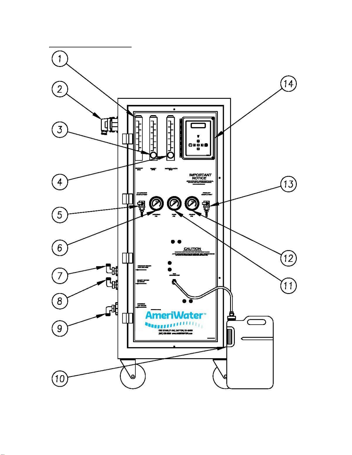
3.1 EXTERNAL FRONT VIEW.............................................................................................................................................. 5
3.2 INTERNAL REAR VIEW ................................................................................................................................................. 7
3.3 ELECTRICAL DIAGRAM, MRO2X, MRO3X, MRO4X &MRO5X...................................................................................... 9
3.4 FLUID DIAGRAM, MRO2X, MRO3X &MRO4X ........................................................................................................... 10
3.5 FLUID DIAGRAM MRO5X .......................................................................................................................................... 11
SECTION 4, MRO STARTUP & OPERATION....................................................................................................................... 12
4.1 CAUTION................................................................................................................................................................... 12
4.2 SAFETY FEATURES..................................................................................................................................................... 14
4.3 INITIAL STARTUP....................................................................................................................................................... 15
4.4 SYSTEM SHUTDOWN ................................................................................................................................................ 17
SECTION 5, DISINFECTING THE SYSTEM........................................................................................................................... 18
5.1 DISINFECTING THE SYSTEM ...................................................................................................................................... 18
5.2 DISINFECTING AN MRO AND “LARGE” LOOP SYSTEM............................................................................................... 23
5.3 AWORD ABOUT HYDROGEN PEROXIDE/PEROXYACETIC ACID ................................................................................. 24
5.4 MEMBRANE FLUSH FEATURE (AUTO FLUSH)............................................................................................................ 25
SECTION 6, MRO CONTROLLER ....................................................................................................................................... 26
6.1 FRONT PANEL CONTROLS AND INDICATORS ............................................................................................................ 26
6.2 CONTROLLER OPERATION ........................................................................................................................................ 27
6.3 CONTROLLER ADJUSTMENTS.................................................................................................................................... 30
6.4 STANDARD SETPOINTS ............................................................................................................................................. 33
6.5 TO DISPLAY OR CHANGE SETPOINTS......................................................................................................................... 35
SECTION 7, EXTERNAL WIRE INSTALLATION.................................................................................................................... 36
SECTION 8, MAINTENANCE ............................................................................................................................................. 37
8.1 MAINTAINING THE SYSTEM ...................................................................................................................................... 37
8.2PT401 ANTI-SCALANT ............................................................................................................................................... 38
8.3 MEMBRANE MAINTENANCE INSTRUCTIONS............................................................................................................ 38
SECTION 9, TROUBLESHOOTING AND REPAIR ................................................................................................................. 40
9.1 TROUBLESHOOTING CHART..................................................................................................................................... 40
9.2 CONTROLLER TROUBLESHOOTING ........................................................................................................................... 43
9.3 PUMP REPAIR ........................................................................................................................................................... 45
9.4 INSTALLING AREPLACEMENT PUMP ASSEMBLY ...................................................................................................... 45
9.5 SOLENOID TEST PROCEDURE .................................................................................................................................... 46
9.6 SOLENOID VALVE REPLACEMENT ............................................................................................................................. 47
SECTION 10, WARRANTY................................................................................................................................................. 47
SECTION 11 SPARE PARTS LISTING .............................................................................................................................. 48
ROUTINE REPLACEMENT ITEMS (NON-DURABLE COMPONENTS) ..................................................................................... 50

MRO2X –5X Manual - 1 - 98-0058
Rev. R
SECTION 1, GENERAL INFORMATION
1.1 INTRODUCTION
Congratulations on your decision to use the MRO system! The MRO is a water treatment
system for use in hemodialysis applications. It is designed to pretreat and purify water resulting
in product water that meets or exceeds ANSI/AAMI RD62 requirements for use in making
dialysate for hemodialysis.
All models of the MRO are shipped completely assembled with required and optional water
treatment components. The model that you purchased was selected for the volume of water
needed and the analysis of your input water. This Operation Manual was written for the
MRO2X, MRO3X, MRO4X, and MRO5X models.
Your MRO system was thoroughly tested and in excellent condition when it was shipped to you.
However, because damage during shipment is possible, please unpack and carefully inspect
the MRO as soon as you receive it. Please notify AmeriWater®if any problems are
encountered.
The initials “PAA” are used occasionally throughout this manual to generically represent the
hydrogen peroxide/peroxyacetic acid solution that is to be used for disinfection. Peracidin®is
an example of this solution. The caution on the front panel of the MRO that states “Use only
PAA/Use no substitutes” means that any of these products are acceptable. Do not attempt to
use anything other than hydrogen peroxide/peroxyacetic acid disinfecting solution.
Please read the Operations Manual before using the system. Contact AmeriWater
Customer Service with any questions at 1-800-535-5585 Monday through Friday 8:00 a.m. to
5:00 p.m. eastern standard time. For after hours emergencies call 1-800-535-5585 and follow
the instructions on the recorded message. Our on-call technician will return your call as soon
as possible.
NOTE: This entire Operations Manual should be read before operating or servicing the
system. This Operations Manual should then be kept near the system and used as a
reference and troubleshooting guide.
WARNING: This Reverse Osmosis System (RO) contains a preservative solution to
prevent microbiological growth and freezing. Discard all product water for at
least two hours of operation before placing the RO in service.
CAUTION: No person should attempt to operate or service the AmeriWater MRO without
prior authorization, instruction, and training from AmeriWater and/or your
medical facility director.
1.2 RESTRICTION ON USE
Federal law restricts this device for sale by or on the order of a physician (medical director) for
use as a water treatment device for hemodialysis.

MRO2X –5X Manual - 2 - 98-0058
Rev. R
SECTION 2, TECHNICAL INFORMATION
2.1 SPECIFICATIONS
Ideal, minimum, and maximum
incoming water temperature
Min = 41° F (5° C) Max = 90° F (33° C)
Ideal Temperature = 77° F (25° C)
Prefilter gauge pressure (when the
MRO is running)
Minimum
Maximum
20 PSI
90 PSI (Pounds per Square Inch)
Pump pressure –
Minimum
Maximum
150 PSI
275 PSI
Water pressure to dialysis machine
Controlled by Loop return relief valve.
Maximum output of product water
@ 77°F (25°C), TDS<1000 ppm of
NaCl, & pump pressure of 200 psi.
MRO2X –4,320 GPD (16,654 LPD)
MRO3X –5,544 GPD (24,981 LPD)
MRO4X –7,401 GPD (33,308 LPD)
MRO5X –9,244 GPD (34,822 LPD)
(Gallons Per Day / Liters Per Day)
Connections
Feed = 3/4” plain hose
Product = 1/2” plain hose
Drain = 3/4” plain hose
Electrical Requirements
For the controller: 115V/60Hz GFI (Ground Fault
Interrupter)
For the pump: 208V, 230V, or 460V three
phase/15 Amp fused disconnect. 220V single
phase/15 Amp fused disconnect
Dimensions Packaged
Dimensions not Packaged
64- ½” H x 42" W x 38" D
59”H x 26”W x 25 ½”D
Shipping Weight / Operation
Weight
MRO2X 340 - 390 lbs. / 265 lbs
MRO3X 370 - 420 lbs. / 300 lbs
MRO4X 400 - 450 lbs. / 335 lbs
MRO5X 430 - 480 lbs. / 370 lbs
Materials that Contact Product Water:
ABS
Polyethylene
Acrylic
Polypropylene
Carbon
Stainless Steel
Nylon
Thin Film Composite Membrane (polyimide)
PVC
Tygon
Polyester
All of the above listed materials meet FDA and/or NSF standards.

MRO2X –5X Manual - 3 - 98-0058
Rev. R
2.2 POWER RATINGS
Voltage
Frequency
Phase
Max Amp Draw
Controller
115
60 Hz
Single
10
2X-4X401 Pump
220
60 Hz
Single
12
2X-4X402 Pump
208
60 Hz
Three
8.8
2X-4X403 Pump
230
60 Hz
Three
7.6
2X-4X404 Pump
460
60 Hz
Three
3.8
5X402 Pump
208
60 Hz
Three
12
5X403 Pump
230
60 Hz
Three
10.1
2.3 MRO OUTPUT WATER QUALITY
The physician in charge of dialysis has the ultimate responsibility for selecting the maximum
allowable levels of chemical contaminants in the water, and, also, is responsible for monitoring
the water. The AmeriWater MRO System is designed to produce water that meets or exceeds
ANSI/AAMI RD62 requirements.
Thin Film Composite Membrane
PT401 Antiscalant/Scale Inhibitor
Contaminants
Chemical Feed System
Membrane Scale Control
Not to exceed 40 ppm
Contaminants
Percentage Removal
Calcium
Magnesium
Sodium
Potassium
Fluoride
Nitrate (NO3)
Sulfate
Copper
Barium
Zinc
Aluminum
Arsenic
Lead
Silver
Cadmium
Chromium
Selenium
Mercury
Antimony
Beryllium
Thallium
99.5
99.5
98.0
97.0
87.0 - 93.0
60.0 - 75.0
99.5
98.0 - 99.0
96.0 - 98.0
98.0 - 99.0
98.0 - 99.0
94.0 - 96.0
96.0 - 98.0
93.0 - 96.0
96.0 - 98.0
96.0 - 98.0
94.0 - 96.0
96.0 - 98.0
96.0 - 98.0
96.0 - 98.0
96.0 - 98.0

MRO2X –5X Manual - 4 - 98-0058
Rev. R
2.4 TEMPERATURE CORRECTED MRO PRODUCTION RATES
MRO membrane performance is affected by water temperature. The Product Water Flow Rate
and Output decreases as the temperature of the Incoming Tap Water decreases.
2.5 ENVIRONMENTAL/TRANSPORT CONDITIONS EXPECTED
ENVIRONMENTAL CONDITIONS ANTICIPATED
This device is intended to be used under the following conditions:
Indoor use;
Altitude up to 2000 m;
Temperature between 5°C and 40°C;
Maximum relative humidity 80% for temperatures up to 31°C decreasing linearly to 50% relative
humidity at 40°C;
MAINS supply voltage fluctuations up to + 10% of the nominal voltage;
Transient overvoltages present on MAINS supply = CATEGORY II;
Applicable RATED POLLUTION degree 2.
TRANSPORT CONDITIONS ANTICIPATED
Altitude up to 2000 m;
Temperature between 5°C and 40°C;
Maximum relative humidity 80% for temperatures up to 31°C decreasing linearly to 50% relative
humidity at 40°C;

MRO2X –5X Manual - 5 - 98-0058
Rev. R
SECTION 3, COMPONENTS AND SCHEMATICS
3.1 EXTERNAL FRONT VIEW

MRO2X –5X Manual - 6 - 98-0058
Rev. R
IDENTIFICATION OF COMPONENTS (EXTERNAL FRONT VIEW)
1. PRODUCT GPM: Rotameter that measures the flow of the Product Water For Dialysis
in gallons per minute (GPM).
2. SIDE ENTRY HOOD: External wire installation for float level switches, pretreat lockout
and RO alarm relay connectors; (See Section 7).
3. REJECT GPM WITH VALVE: Rotameter with valve to control the flow of the Reject
water to drain, in gallons per minute (GPM).
4. RECIRCULATING GPM: Rotameter with valve to control the flow of water being
recirculated back before the pump, in gallons per minute (GPM).
5. INCOMING TAP WATER TEST PORT: Valve for taking sample of feed water before the
RO.
6. INCOMING TAP WATER PSI: Gauge that measures the pressure (in pounds per
square inch) of the Incoming Tap Water.
7. PRODUCT WATER FOR DIALYSIS: Connection carrying Product Water For Dialysis.
8. REJECT WATER TO DRAIN: Connection carrying Reject to the drain.
9. INCOMING TAP WATER: Hose carrying Incoming Tap Water that is to be treated by
the RO.
10. PAA JUG: Plastic jug to mix hydrogen peroxide/peroxyacetic acid (PAA) disinfecting
solution and water for sanitizing the system; pre-marked with a red Fill Line to indicate
how much water to add.
11. REJECT PSI: Gauge that measures the pressure (in pounds per square inch) of the
water coming from reject side of the membranes.
12. PUMP PSI: Gauge that measures the pressure (in pounds per square inch) of the water
coming from the pump feeding the membranes.
13. PRODUCT WATER TEST PORT: Valve for taking sample of Product Water.
14. CONTROLLER: Control mechanism for the RO. See Section 6.

MRO2X –5X Manual - 7 - 98-0058
Rev. R
3.2 INTERNAL REAR VIEW

MRO2X –5X Manual - 8 - 98-0058
Rev. R
IDENTIFICATION OF COMPONENTS (INTERNAL REAR VIEW)
15. MOTOR CONTACTOR/OVERLOAD RELAY: Starts and stops the pump motor and
protects the motor from overload.
16. CLEAN IN PLACE SWITCH (ALARM FAULT OVERRIDE): When the Clean In Place
(CIP) switch is placed to the ON position, all RO+ fail-safe modes are disabled for low-
pressure membrane cleaning with the optional AmeriWater Clean In Place system (P/N
00CIP2). The controller will display a warning that the CIP mode is active.
17. MEMBRANE: Fiberglass wrapped, spiral-wound, thin film composite membrane for
reverse osmosis.
18. PUMP: Provides the driving pressure for the reverse osmosis system.
19. PRODUCT HEADER ASSY: This header directs all product water from the membranes
to the flow meter.
20. INCOMING CONDUCTIVITY SENSOR: Cell that reads the quality of the feed water.
21. PRODUCT TO DRAIN SOLENOID: Opens when water quality is below set point.
22. PRODUCT TO USE SOLENOID: Closes when water quality is below set point.
23. DISINFECT SOLENOID ASSEMBLY: Opens to allow the hydrogen peroxide/
peroxyacetic acid mixture to draw into the system to soak for the sanitize cycle.
24. FEED SOLENOID ASSEMBLY: Opens when the MRO system is on to allow water to
feed through the system, closes when the system is OFF.
25. DISINFECT EJECTOR: Causes suction to draw solution from PAA jug when the
Disinfect Solenoid is opened.
26. LOW PRESSURE SWITCH: Switch to protect the pump in the event that the feed
pressure drops below 20 PSI.
27. PRODUCT CONDUCTIVITY SENSOR: Cell that reads the quality of the product water.

MRO2X –5X Manual - 9 - 98-0058
Rev. R
3.3 ELECTRICAL DIAGRAM, MRO2X, MRO3X, MRO4X & MRO5X

MRO2X –5X Manual - 10 - 98-0058
Rev. R
3.4FLUID DIAGRAM, MRO2X, MRO3X & MRO4X

MRO2X –5X Manual - 11 - 98-0058
Rev. R
3.5 FLUID DIAGRAM MRO5X

MRO2X –5X Manual - 12 - 98-0058
Rev. R
SECTION 4, MRO STARTUP & OPERATION
4.1 CAUTION
NOTE: This entire Operations Manual should be read before operating or servicing
the MRO system. The Operations Manual should then be kept near the
system and used as a reference and troubleshooting guide.
WARNING:This Reverse Osmosis System (RO) contains a preservative solution to
prevent microbiological growth and freezing. Discard all product water for at
least two hours of operation before placing the RO in service.
CAUTION: No person should attempt to operate or service the MRO without prior
authorization or instruction from your medical facility director.
The following operating or water supply conditions could cause an accident or the MRO system
to fail:
1. The electrical source must be single phase, 3-conductor type provided with a hospital grade
receptacle and a ground fault interrupter (GFI) at 115V, 60Hz. The proper polarity and
ground integrity must be initially checked and thereafter maintained. Failure to do so may
result in electrical shock to the operator or patient. It is suggested that the MRO be placed
on an electrical supply with emergency backup.
2. The MRO must only be plugged directly into a GFI receptacle. It must not be plugged into
an extension cord or power strip that could cause low amperage.
3. All local plumbing and electrical requirements should be met.
To avoid electrical shock, always unplug the MRO system before opening the
face of the electrical controller.
4. Incoming water should be between 41° F and 90° F (5° C and 33° C). It is not
recommended to use water at temperatures below 41° F (5° C) because it will reduce
membrane performance significantly. Use only the cold water supply unless using an
automatic blending valve to get 77° F (25° C) water. Never use water warmer than 90° F
(33° C).
5. Water with silt density index (SDI) above 5 SDI will foul the membrane.
6. It is important to test for chlorine and chloramines at the CHLORAMINES SAMPLE PORT
before each use of the system. Chlorine will deteriorate the membrane and cause system
failure. It is recommended to use a Total Chlorine test kit, such as Water Check 2 Low
Level Chlorine/Chloramines Test Strips (P/N 97CM20201).
7. Incoming tap water pH should be within EPA National Secondary Drinking Water
Regulations of 6.5 - 8.5. Incoming tap water with pH higher or lower than the regulation may
cause higher conductivity in the product water. If the water changes drastically, the
membrane will be harder to clean. Periodically check the pH of the incoming tap water to

MRO2X –5X Manual - 13 - 98-0058
Rev. R
verify that it is within the specified range (pH Water/Bicarbonate/Dialysate Test Strips P/N
97PH20901).
CAUTION: Mixing chlorine and hydrogen peroxide/peroxyacetic acid causes a toxic
chemical reaction. Never allow them to mix! Do not use chlorine to disinfect
the system!
8. Use only the exact amount of hydrogen peroxide/peroxyacetic acid disinfectant solution
(PAA) and in proper dilution during disinfection of the system.
9. It is important to test for PAA in the Product Water after rinsing during disinfection of the
system. Do not use the system until all traces of the disinfecting solution in the Product
Water are gone.
CAUTION: Never operate the MRO connected to dialysis machines if the water
conductivity exceeds the set point, indicating Poor Quality!
10.Always maintain water flow and pressure to avoid damage to the pump.
11.Minimum feed pressure is 20 PSI (while the MRO is in operation, with flow). Maximum feed
pressure is 90 PSI.
12.If the system is operated without a micron prefilter, the membranes will foul.
WARNING: The Clean In Place Switch, located inside the cabinet on the back of the
controller, must be in the OFF position during normal operation. If the
Clean In Place Switch is left in the ON position during normal operation, all
MRO fail-safe modes will be disabled, and damage to the MRO or injury to
the patient may occur.
13. Minimize the opportunities for bacterial growth between uses!
Whenever the MRO is not used for a period of several hours, and connected to a Direct
Feed Loop, the “Membrane Flush Feature” of the MRO should be programmed to be
active when in the STANDBY mode (See section 5 for activating this feature).
Whenever the MRO is not used for a period of several hours, and connected to a
Storage Tank of a Central System, the “Membrane Flush Feature” of the MRO should be
programmed to be active when in the OPERATE mode (See section 5 for activating this
feature). This feature will flush the MRO when the Storage Tank is full and the water
level is maintained at the Tank Full High float switch by diverting the Product Water to
drain.
Before determining a bacteria count, the MRO should be PLACED in FLUSH for 5
minutes (fully opened reject flow control knob), and then placed in OPERATE for 5 –10
additional minutes after a period of non-use, but before taking a sample of the
PRODUCT WATER. Bacteria are known to increase in population when water is not
moving.

MRO2X –5X Manual - 14 - 98-0058
Rev. R
4.2 SAFETY FEATURES
The MRO is equipped with several safety features for the benefit of both the user and the
patient. They consist of the following:
1. Disinfection using (PAA) disinfecting solution instead of formaldehyde increases safety and
avoids health risks associated with formaldehyde. PAA produces no harmful by-products or
side effects, thus it is safer for patients. Using PAA does not require additional ventilation,
and disposal is safe and easy. Important information regarding the usage and handling of
PAA is listed in Section 5.3, A WORD ABOUT HYDROGEN PEROXIDE/PEROXYACETIC
ACID, and in PAA Materials Safety Data Sheet. Please read them carefully.
2. INCOMING TAP WATER, PRODUCT WATER and REJECT WATER TO DRAIN hoses are
labeled to prevent incorrect connections.
3. Low pressure shutdown protects the pump if the feed pressure drops below 20 PSI.
4. An audible alarm sounds whenever water quality drops to an unacceptable level.
WARNING: The AmeriWater model MRO 2X through 5X is considered a non-portable
device. It can be connected to a Direct Feed Loop system or a Storage Tank
system. For this reason, there is a divert to drain on this model.
TERMINATE TREATMENT IMMEDIATELY IF WATER QUALITY FALLS OUT
OF SPECIFICATION WHEN NO STORAGE TANK IS BEING USED. The
Product water will divert to drain as long as the conductivity is out of
specification (no water will be sent to the Storage Tank). The poor quality
alarm for the MRO will sound, but the water that is already in the storage
tank can continue to be used.

MRO2X –5X Manual - 15 - 98-0058
Rev. R
4.3 INITIAL STARTUP
WARNING: This Reverse Osmosis System (RO) contains a preservative solution to
prevent microbiological growth and freezing. Discard all product water for
at least two hours of operation before placing the RO in service.
1. Lock the two front casters so that the RO+ will remain stationary during startup.
2. Remove the protective covers from the PRODUCT WATER, REJECT WATER TO DRAIN
and INCOMING TAP WATER barbed fittings on the side of the MRO.
3. Slide the hose clamps over the hoses that were
provided in the installation package for holding the 3
hoses in place on the MRO.
4. Slip the INCOMING TAP WATER, PRODUCT WATER
and REJECT WATER TO DRAIN hoses over the
appropriate barbed fitting, then secure each with a
hose clamp.
CAUTION: To assure proper assembly, hoses MUST
be fully inserted over the barbed area and
a little beyond for the clamp to hold in the
“necked-down” area of the barbed fitting.
5. Connect the MRO INCOMING TAP WATER hose to
the potable cold water supply using the Incoming Tap
Water hose and fittings supplied. If blending both warm
and cold water to improve product flow rate, do not
exceed 90° F (33° C).
6. The REJECT WATER TO DRAIN hose coming out of the MRO system is for reject water.
The water from this hose will always go down a sink drain. Leave at least a 2" air gap
between the hose and the drain to prevent contamination or siphoning.
7. The PRODUCT WATER hose should also be secured to the sink until the start-up flush and
initial disinfection cycle are completed, and the water quality is in the good range (below the
conductivity setpoint, and not in alarm).
8. Open the access cover and make sure that the “CIP” switch is in the “OFF” position.
9. Plug the power cord into a dedicated 115-volt GFI receptacle.
10.The high voltage power cord must be connected to an appropriately sized disconnect for the
voltage and the phases used. Connection to a wall disconnect must be done by a qualified
electrician.

MRO2X –5X Manual - 16 - 98-0058
Rev. R
11.If a plug on the high voltage power cord has been installed, there must be a matching “twist
lock” high voltage polarized receptacle that has been installed by a qualified electrician.
For 3 phase applications, the 3-wire connections must be verified to give the
correct rotation on the MRO pump. If not, specified pressure cannot be obtained,
and the pump will quickly overheat.
12.Turn on the potable water supply to the MRO. Allow the membranes to fill with water. This
may take up to 5 minutes. Failure to do so may cause damage to the MRO.
13.Turn on the MRO by pressing the POWER key, and allow it to run making sure the water is
properly flowing out the Reject and Product hoses.
14.Turn the REJECT FLOW CONTROL KNOB located at the bottom of the Reject Flow meter
counter-clockwise to allow the MROZ to run in full-flow Reject flush for about 15 minutes.
15.After 15 minutes, turn the REJECT FLOW CONTROL KNOB clockwise so that the Reject
flow is approximately equal to the Product water flow. Allow the product water to flow to
drain for 2 hours to ensure that all preservative is rinsed out of the system. Check for leaks
during this time.
NOTE: The MRO conductivity alarm may sound, which is normal when the MRO is in FLUSH.
Press the ALARM SILENCE key on the MRO controller to silence the alarm. The
alarm will restart after a 3 minute delay.
16.The conductivity value, after flushing and being put back into the service mode, must be
within the acceptable limit.
17.After a thorough flushing of the preservative, the MRO must be disinfected prior to being put
into service for dialysis use. (See Disinfecting The System, Section 5).
18.When all disinfection procedures have been completed, turn on the feed water supply.
19.Press the POWER key (the display will show OPERATING after a 10 second delay).
NOTE: The conductivity may alarm for a few seconds before dropping into the desired range.
WARNING: Do not use the MRO to feed a dialysis machine until all specifications are
met.
20.Press the POWER key (the display will show STANDBY). Connect the PRODUCT WATER
hose to the Direct Feed Loop or Storage Tank inlet. (Be sure to connect the Product
Water hose aseptically).
CAUTION: Although the water treatment system may produce water of sufficient quality
to meet the requirements of AAMI standards, distribution of the water may
degrade its quality to the point where it no longer meets the requirements of
this standard. AmeriWater offers information about ultra pure water piping to
prevent the degradation of product water in a water loop or central system.
This manual suits for next models
4
Table of contents