INSTALLATIONS
MI890 User’s Manual 3
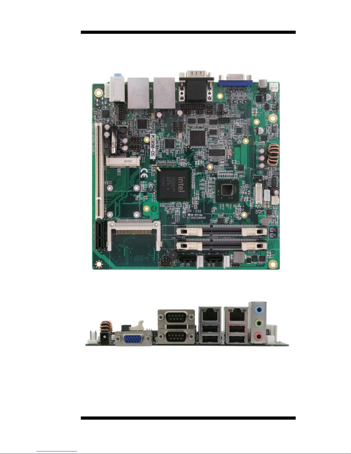
MI890 Specifications
MI890-N4/ MI890-D4 / MI890-D5
Intel® AtomTM SC N455 (512KB L2 cache, 1 Core/ 2 Threads. TDP=6.5W)
Intel® AtomTM SC D425 (512KB L2 cache, 1 Core/ 2 Threads. TDP=10W)
Intel® AtomTM DC D525 (1MB L2 cache, 2 Core/ 2 Threads. TDP=13W)
22mm x 22mm, Micro-FCBGA8
1.66GHz (N455) / 1.80GHz(D425/D525)
ICH8M: 31mm x 31mm, 676-pin T-PBGA (2.4W)
DDR3-800 (Single channel)
SO-DIMM x2 (Non-ECC), Max.= 2GB(N455) / 4GB(D425/D525)
Intel® Integrated Graphics Controller
Supports DirectX 9 Graphic (200MHz for N455 ; 400MHz for D425/D525)
18-bit one channels LVDS interface w/DF13 socket x1
Intel 82583V x 2 for Dual GbE
ICH8M built-in USB 2.0 host controller, support 9 ports
ICH8M built-in SATA controller, supports 2 ports
ICH8M built-in one channel Ultra DMA 33/66/100, for CF Type II
(Component side)
Intel ICH8M built-in HD audio controller
w/ Realtek ALC269 Codec with integrated 2W amplifier (4 Ohm)
Supports 2 Channel audio (Line-out & Line-in )
COM1 (RS232/422/485), COM2~COM4(RS232)
with pin-9 with power for 2 ports (500 mA for each port) [COM3/4]
Hardware monitor (2 thermal inputs, 4 voltage monitor inputs, VID0-4 &
Mini PCI-e x 1 w/USB for WiFi or TV-tuner module
(Reserved screw holes for half-mini type also)
PCI slot x 1 + PCI-Express(1x) slot x1
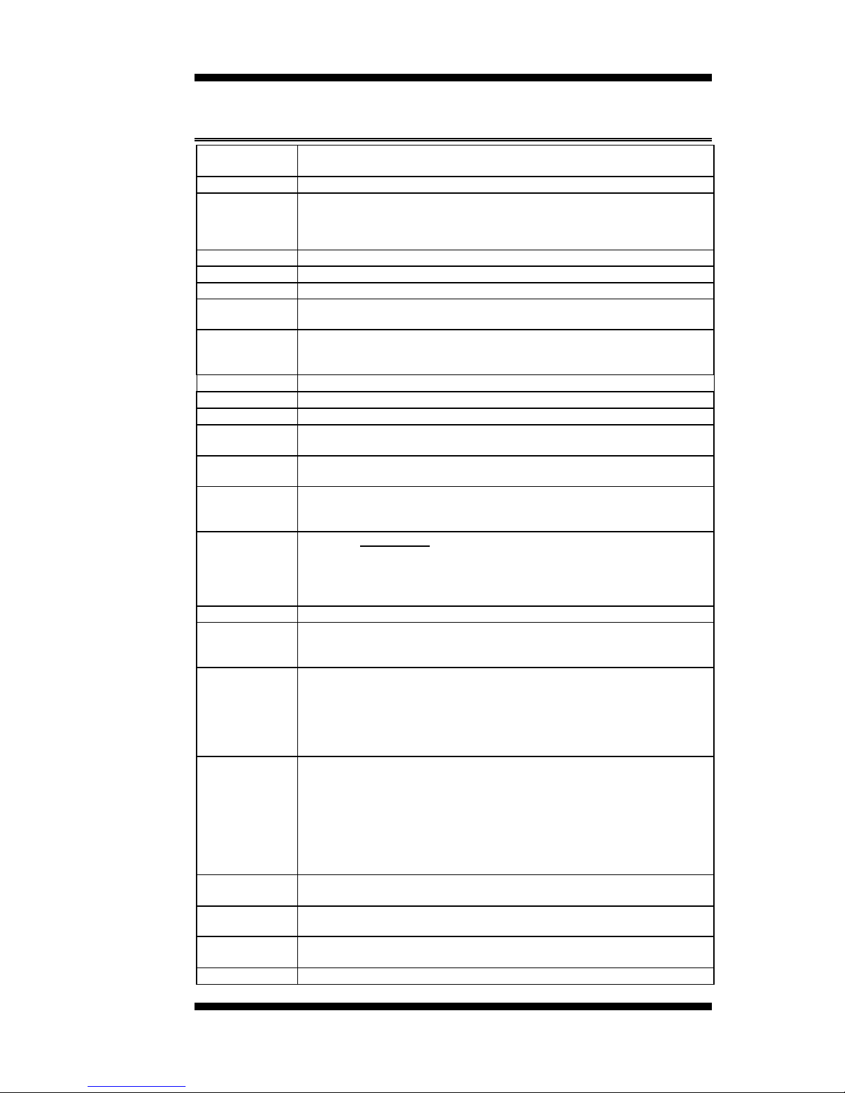
DB15 connector x1 for VGA
Dual DB9 Stack connector x 1 for COM1/ COM2
RJ45 + Dual USB stack connector x1 for LAN 1 + USB 1/2
RJ45 + Dual USB stack connector x1 for LAN 2 + USB 3/4
Audio 3-port connector x 1 (Line-out , Line-in& Mic)
2x4 pin header x2 for 4 USB ports
DF13 socket x 1 for LVDS( 18-bit single channel)
DF11 socket 20-pin connector x 1 for COM3, COM4
CF type II connector x1
SATA II connector x2
2x5 pin header x1 for Digital I/O
2x6 pin header x1 for front audio
4-pin header x2 for SATA power (Mini type)
Yes (256 segments, 0, 1, 2…255 sec/min)
Optional EuP feature (Fintek F75160)
UL 60950-1 2