AMI MI987 User manual

MI987
Intel® Q87 / H81 Based Mini-ITX board
Mini ITX Motherboard
USER’S MANUAL
Version 1.0

ii
MI987 User’s Manual
Acknowledgments
AMI is a registered trademark of American Megatrends Inc.
PS/2 is a trademark of International Business Machines
Corporation.
Intel and Intel® 4th Generation Core DC/QC Processor are
registered trademarks of Intel Corporation.
Microsoft Windows is a registered trademark of Microsoft
Corporation.
Fintek is a registered trademark of Fintek Electronics Corporation.
All other product names or trademarks are properties of their
respective owners.

MI987 User’s Manual iii
Table of Contents
Introduction.......................................................1
Product Description...................................................................... 1
Checklist....................................................................................... 1
MI987 Specifications ................................................................... 2
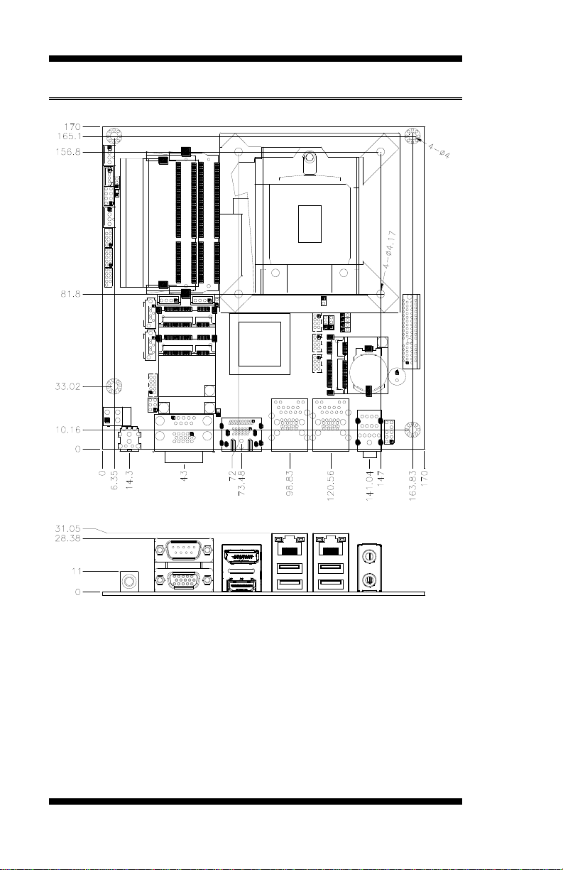
Board Dimensions........................................................................ 4
Installations.......................................................4
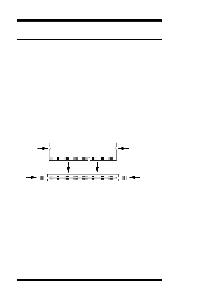
Installing the Memory .................................................................. 6
Setting the Jumpers ...................................................................... 7
Connectors on MI987................................................................. 12
BIOS Setup.......................................................23
Drivers Installation......................................45
Intel Chipset Software Installation Utility.................................. 46
VGA Drivers Installation ........................................................... 47
Realtek HD Audio Driver Installation........................................ 48
LAN Drivers Installation............................................................ 49
Intel® Management Engine Interface ........................................ 50
Intel® USB 3.0 Drivers.............................................................. 51
Appendix............................................................53
A. I/O Port Address Map ........................................................... 53
B. Interrupt Request Lines (IRQ)............................................... 54
C. Digital I/O Sample Code ....................................................... 55
D. Watchdog Timer Configuration............................................. 60

iv
MI987 User’s Manual
This page is intentionally left blank.

INTRODUCTION
MI987 User’s Manual 1
Introduction
Product Description
The MI987 Mini ITX motherboard is based on the latest Intel®Q87
chipset. The platform supports Intel® 4th Generation CoreTM DT
i7/i5/i3 processors.
The latest Intel®processors provide advanced performance in both
computing and graphics quality. This meets the requirement of customers
in the gaming, POS, digital signage and server market segment.
The platform supports two SO-DIMM sockets that can accommodate up
to 16GB of DDR3-1600 Non ECC memory. The Intel® 4th Gen. Core™
DT processor integrated HD graphics supports 3 independent displays,
Direct X 11.1, OpenGL 3.2, and Open CL 1.2. Display interfaces are for
HDMI, DisplayPort and VGA CRT.
With two Gigabit Ethernets, the MI987 Mini ITX board utilizes the
dramatic increase in performance provided Intel’s latest cutting-edge
technology. Expansion is provided by PCIe(4x), two full sized MiniPCIe
and a half sized MiniPCIe. Onboard connectors support 2x SATAIII, 4x
or 6x USB 2.0 depending on the MI987 model and 2x COM ports. The
board measures 170mm x 170mm.
Checklist
Your MI987 package should include the items listed below.
The MI987 MINI ITX motherboard
This User’s Manual
1 CD containing chipset drivers and flash memory utility
Cables???????????????

INTRODUCTION
2
MI987 User’s Manual
MI987 Specifications
Product
Name
MI987AF (Q87)
MI987EF (H81)
MI987AF-W (Q87) [Optional for iBASE SG]
Form Factor
Mini ITX
CPU Type
- Intel®4th Generation CoreTM DT i7/i5/i3 processors (22nm monolithic)
**Recommend to use low power DT CPU @ TDP 35W/45W**
CPU Speed
Up to 2.7GHz
Cache Size
Up to 8MB
CPU Socket
LGA1150 (Socket H3)
Chipset
Intel®Q87 PCH [MI987AF/MI987AF-W]
Intel®H81 PCH [MI987EF]
Package =23 mm x 22 mm, 0.65 mm ball pitch
BIOS
AMI BIOS
Memory
Intel®4th Gen CoreTM DT processors integrated memory controller,
-DDR3-1600 M[email protected]
-SO-DIMM x 2, Max. 16GB (Non-ECC) [Horizontal type]
VGA
Intel®4th Gen. CoreTM DT processor integrated HD Gfx, supports 3
independent displays, Direct X 11.1, OpenGL 3.2, Open CL 1.2
-HDMI x 1 (Thru port B, with Level shifter PTN3360D)
-DisplayPort x 1 (Thru port C) **support DP++**
-VGA x 1 (Thru PCH)
LAN
1. Intel® I217LM PHY [MI987AF/-W] or I217V GbE PHY [MI987EF]
2. Intel® I211AT PCIe GbE as 2nd LAN
USB
USB 2.0 host controller [Q87/H81 Integrated]
-[MI987AF/-W] : 6 ports via onboard pin header
-[MI987EF] : 4 ports thru pin header+ 2 ports @edge I/O connectors
-2 ports via MiniPCIe socket
USB 3.0 host controller [Q87 /H81 Integrated] @ edge I/O connectors
-USB 3.0 x 4 ports for MI987AF/-W
-USB 3.0 x 2 ports for MI987EF
Serial ATA
Intel®Q87/ H81 PCH built-in SATA controller,
-2x SATA 3.0 (6Gbps)
-2x mSATA [Q87 PCH Port 3/4 for SATA (3.0) or H81 PCH Port 3/4
for SATA(2.0)]
Storage
Device
mSATA x 2thru full-sized/half-sized Mini-PCIe socket @J12/J13 socket
Audio
Intel®Q87/H81 PCH built-in High Definition Audio controller + Realtek
ALC662 w/ 5.1 channels
LPC I/O
Nuvoton NCT5523D (64-pin LQFP [7 mmx7 mm])
- COM #1 (RS232/422/485) support ring-in with power @500 mA
(selectable for 5V or 12V) [EXAR SP339EER1 232/422/485 transceiver x
1 for jumper-less]
- COM #2 (RS232 only)
Hardware Monitor (2 thermal inputs,4 voltage monitor inputs & 2 Fan
headers)
- CPU FAN x 2 (PWM/DC type, 4-pin connector type, auto-detection by
Nuvoton NCT3943S fan controller)
Digital IO
4 in & 4 out
IAMT 9.0
MI987AF/-W only
TPM 1.2
Infineon SLB9655 [MI987AF/-W only]

INTRODUCTION
MI987 User’s Manual 3
Expansion
Slots
- PCIe (4x) x1 [Gen 3.0 PEG] [MI987AF/EF]
- MiniPCIe socket x 2[Full-sized + Half-sized stack type, Full-sized
support PCIe/USB/mSATA, Half-sized support mSATA only]
- Half-sized socket x 1(3rd Mini-PCIe@J16, support PCIe / USB)
Edge
Connectors
DC-Jack x 1(C12135112DC102000P)
DB9+DB15 stack connector for COM #1 + CRT
DP + HDMI stack connector x 1
Dual USB (3.0) + RJ45 stack connector x 2
** For MI987EF, USB 3.0 @ CN7 is USB2 only**
Audio Jack 2 x 1 for MIC-in / Line-out (Reserved for 2-port connector)
Onboard
Header/Conn
ector
2 ports x SATA III [Blue color]
DF-11 2x4 pins pin-header x 3 for 6 ports USB 2.0 (MI987AF/-W)
DF-11 2x4 pins pin-header x 2 for 4 ports USB 2.0 (MI987EF)
DF-11 2x6 pins pin-header x 1 for front panel audio
DF-11 2x5 pins box header x 1 for COM2 (RS232)
2x5 pins pin-header x1 for Digital IO
4 pins mini-type header for SATA device power x 2 [JST type]
2 x 4 pins pin header x 1 for front I/O (2.54 pitch)
Watchdog
Timer
Yes (256 segments, 0, 1, 2…255 sec/min)
System
Voltage
+19V DC-in (±20%)
Other
-LAN Wakeup
-EuP/ErP (MI987EF only, thru Super I/O)
-iSMART function(TI MSP430G2433 MCU)
-Legacy Free from super I/O
-AT24C02C EEPROM [SO8 type] via SMbus
Board Size
170mm x 170mm
Operation
System
Windows 7, Windows 8

INTRODUCTION
4
MI987 User’s Manual
[
Board Dimensions
Installations
This section provides information on how to use the jumpers and
connectors on the MI987 in order to set up a workable system. The topics
covered are:
Installing the Memory........................................錯誤! 尚未定義書籤。
Setting the Jumpers............................................錯誤! 尚未定義書籤。

INSTALLATIONS
MI987 User’s Manual 5
Connectors on MI987 ........................................錯誤! 尚未定義書籤。

INSTALLATIONS
6
MI987 User’s Manual
Installing the Memory
The MI987 board supports two DDR3 memory modules for a maximum
total of 16GB in DDR3 SODIMM memory type.
Installing and Removing Memory Modules
To install the DDR3 modules, locate the memory slot on the board and
perform the following steps:
1. Hold the DDR3 module so that the key of the DDR3 module aligned
with that on the memory slot.
2. Gently push the DDR3 module in an upright position until the clips of
the slot close to hold the DDR3 module in place when the DDR3
module touches the bottom of the slot.
3. To remove the DDR3 module, press the clips with both hands.
DDR3 Module
Lock
Lock
Lock
Lock

INSTALLATIONS
MI987 User’s Manual 7
Setting the Jumpers
Jumpers are used on MI987 to select various settings and features
according to your needs and applications. Contact your supplier if you
have doubts about the best configuration for your needs. The following
lists the connectors on MI987 and their respective functions.
Jumper Locations on MI987.................................................................. 8
JP1: COM1 RS232 RI/+5V/+12V Power Setting.................................. 9
JP8: Flash Descriptor Security Override (Factory use only).................. 9
JBAT1: Clear CMOS Contents............................................................ 10
J15: DP++ Select................................................................................. 10
JP10: Power On Type.......................................................................... 11

INSTALLATIONS
8
MI987 User’s Manual
Jumper Locations on MI987
Jumpers on MI987 ........................................................................... Page

INSTALLATIONS
MI987 User’s Manual 9
JP1: COM1 RS232 RI/+5V/+12V Power Setting
JP1
Setting
Function
Pin 1-3
Short/Closed
+12V
Pin 3-4
Short/Closed
RI
Pin 3-5
Short/Closed
+5V
JP8: Flash Descriptor Security Override (Factory use only)
JP8
Flash Descriptor Security Override
Open
Disabled (Default)
Close
Enabled
6
2
5
1
1 2

INSTALLATIONS
10
MI987 User’s Manual
JBAT1: Clear CMOS Contents
JBAT1
Setting
Function
Pin 1-2
Short/Closed
Normal
Pin 2-3
Short/Closed
Clear CMOS
J15: DP++ Select
JP15
Function
Short
Display Port
Open
Dongle /DP to DVI / DP to HDMI
3
1
1
2

INSTALLATIONS
MI987 User’s Manual 11
JP10: Power On Type
JP10
Function
1-2
ATX Mode (Default)
2-3
AT Mode
3
1

INSTALLATIONS
12
MI987 User’s Manual
Connectors on MI987
Connector Locations on MI987 ...........................................................13
CN4: CRT/COM1 Connector ..............................................................14
CN5: DP/HDMI Connector .................................................................14
CN6: Gigabit LAN (Intel I217LM) / USB3.0......................................14
CN7: Gigabit LAN (Intel I211AT) / USB3.0(EF Ver with USB2.0)...14
CN2, CN3: SATA3 Connectors...........................................................14
F_USB1/2/3: USB Connectors ............................................................14
J2: Digital I/O ......................................................................................15
J4: Front Panel Function Connector.....................................................16
J5: SPI Flash Connector (Factory use only).........................................17
J6: MCU Flash Connector (factory use only).......................................17
J7: DC-in Jack (19V) ...........................................................................17
JP9: Audio Front Header .....................................................................18
J10/J14: HDD Power Connector (Output Only) ..................................18
J12: Mini PCIE/mSATA Connector ....................................................19
J13: mSATA Connector.......................................................................19
J16: Mini PCIE Connector...................................................................19
J8: COM2 Connector...........................................................................19
PCIE1: PCIE_x4 Slot...........................................................................20
CPU_FAN1: CPU Fan Power Connector ............................................21
SYS_FAN1: System Fan1 Power Connector.......................................21

INSTALLATIONS
MI987 User’s Manual 13
Connector Locations on MI987

INSTALLATIONS
14
MI987 User’s Manual
CN4: CRT/COM1 Connector
CN5: DP/HDMI Connector
CN6: Gigabit LAN (Intel I217LM) / USB3.0
CN7: Gigabit LAN (Intel I211AT) / USB3.0(EF Ver with USB2.0)
CN2, CN3: SATA3 Connectors
F_USB1/2/3: USB Connectors
Signal Name
Pin
Pin
Signal Name
VCC
1
2
GND
D0-
3
4
D1+
D0+
5
6
D1-
GND
7
8
VCC
2
8
1
7

INSTALLATIONS
MI987 User’s Manual 15
J2: Digital I/O
Signal Name
Pin
Pin
Signal Name
GND
1
2
VCC
OUT3
3
4
OUT1
OUT2
5
6
OUT0
IN3
7
8
IN1
IN2
9
10
IN0
9
1
10
2

INSTALLATIONS
16
MI987 User’s Manual
J4: Front Panel Function Connector
ATX Power ON Switch: Pins 1 and 2
This 2-pin connector is an “ATX Power Supply On/Off Switch” on the
system that connects to the power switch on the case. When pressed, the
power switch will force the system to power on. When pressed again, it
will force the system to power off.
Hard Disk Drive LED Connector: Pins 3 and 4
This connector connects to the hard drive activity LED on control panel.
This LED will flash when the HDD is being accessed.
Pin #
Signal Name
4
HDD Active
3
3.3V
Reset Switch: Pins 5 and 6
The reset switch allows the user to reset the system without turning the
main power switch off and then on again. Orientation is not required
when making a connection to this header.
Power LED: Pins 7 and 8
Pin #
Signal Name
7
+5V
8
GND
8
2
7
1
This manual suits for next models
3
Table of contents
Other AMI Motherboard manuals