amig 350 MIG User manual


1
Dear Customer
This instruction manual will help you get to know your new machine. Read the manual
carefully and you will soon be familiar with all the many great features of your new
product. Meanwhile, please remember well safety rules and operate as instruction.
If you treat your product carefully, this definitely helps to prolong its enduring quality
and Reliability things which are both essential prerequisites for getting outstanding
results.
Production specification may change without advance notice.
The model you purchase is for:
AMIG500/630PD
Please find corresponding models from the "Contents".
Important:
Please take special note of safety rules and operate as instruction in case of damage
and serious injury.

2
Safety Rules
“Danger”indicates an imminently hazardous situation which, if not avoided, will result in death or
serious injury.
“Warning!”indicates a possible hazardous situation which, if not avoided, could result in death or
serious injury. The possible hazards are explained in the text.
“Caution”indicates a possible hazardous situation which, if not avoided, may result in slight or
moderate injury.
“Note!”indicates a situation which implies a risk of impaired welding result and damage to the
equipment.
“Important!” indicates practical tips and other useful special-message. It is no signal word for a
harmful or dangerous situation.
Utilization for intended purpose only
•The machine may only be used for jobs as defined by the “Intended purpose”.
•Utilization for any other purpose, or in any other manner, shall be deemed to be “not in accordance
with the intended purpose”. The manufacturer shall not be liable for any damage resulting from such
improper use.
Safety signs
•All the safety instructions and danger warnings on the machine must be kept in legible condition, not
removed, not be covered, pasted or painted cover.
Safety inspection
•The owner/operator is obliged to perform safety inspection at regular intervals.
•The manufacturer also recommends every 3-6 months for regular maintenance of power sources.
Electric shock can kill
•Touching live electrical parts can cause fatal shocks or severe burns. The electrode and work circuit
is electrically live whenever the output is on. The input power circuit and machine internal circuits are
also live when power is on. In MIG/MAG welding, the wire, drive rollers, wire feed housing and all
metal parts touching the welding wire are electrically live. Incorrectly installed or improperly grounded
equipment is a hazard.
•Do not touch live electrical parts of the welding circuit, electrodes and wires with your bare skin or wet
clothing.
•The operator must wear dry hole-free insulating welding gloves and body protection while performs
the welding.
•Insulate yourself from work and ground using dry insulating protection which is large enough to
prevent you full area of physical contact with the work or ground.
•Connect the primary input cable according to rules. Disconnect input power or stop machine before
installing or maintenance.
•If welding must be performed under electrically hazardous conditions as follow: in damp locations or
wearing wet clothing; on metal structures such as floors, gratings, or scaffolds; when in cramped
positions such as sitting, kneeling, or lying; or in occasion when there is a high risk of unavoidable or
accidental contact with the work piece or ground. Must use additional safety precautions:
semiautomatic DC constant voltage (wire) welder, DC manual (Stick) welder and AC welder with
reduced open-load voltage.
•Maintain the electrode holder, ground clamp, welding cable and welding machine in good, safe
operating condition. Replace damaged part immediately.
Electric and magnetic fields (EMF) may be dangerous
•If electromagnetic interference is found to be occurring, the operator is obliged to examine any
possible electromagnetic problems that may occur on equipment as follow:
-mains, signal and data-transmission leads
-IT and telecoms equipment
-measurement and calibration devices
-Wearers of pacemakers
•Measures for minimizing or preventing EMC problems:
-Mains supply
If electromagnetic interference still occurs, despite the fact that the mains connection in accordance
with the regulations, take additional measures
-Welding cables
Keep these as short as possible
Connect the work cable to the work piece as close as possible to the area being welded.

3
Lay term well away from other cables.
Do not place your body between your electrode and work cables.
-Equipotential bonding
-Workpiece grounding (earthing)
-Shielding
Shield the entire welding equipment and other equipment nearby.
ARC rays can burn
•Visible and invisible rays can burn eyes and skin.
•Wear an approved welding helmet or suitable clothing made from durable flame-resistant material
(leather, heavy cotton, or wool) to protect your eyes and skin from arc rays and sparks when welding
or watching.
•Use protective screens or barriers to protect other nearby personnel with suitable, non-flammable
screening and/or warn them not to watch the arc nor expose themselves to the arc rays or to hot
spatter or material.
Fumes and gases can be dangerous
•Welding may produce fumes and gases, breathing these fumes and gases can be hazardous to your
health.
•When welding, keep your head out of the fume. If inside, ventilate the area at the arc to keep fumes
and gases away from the breathing zone. If ventilation is not good, wear an approved air-supplied
respirator.
•Work in a confined space only if it is well ventilated, or while wearing an air-supplied respirator.
•Welding fumes and gases can displace air and lower the oxygen level causing injury or death. Always
use enough ventilation, especially in confined areas, to insure breathing air is safe.
Welding and cutting sparks can cause fire or explosion
•When not welding, make sure the electrode circuit is not touching the work or ground. Accidental
contact can cause sparks, explosion, overheating, or fire. Make sure the area is safe before doing
any welding.
•Welding and cutting on closed containers, such as tanks, drums, or containers, can cause them to
blow up. Make sure proper steps have been taken.
•When pressure gas is used at the work site, special precautions are required to prevent hazardous
situations.
•Connect work cable to the work as close to the welding zone as practical to prevent welding current
from passing too long and creating fire hazards or overheat.
•Wear oil-free protective garments such as leather gloves, heavy shirt, cuffless trousers, high shoes,
and a cap. Wear ear plugs when welding out of position or in confined places. Always wear safety
glasses with side shields when in a welding area.
•Be attention that welding sparks and hot materials from welding can easily go through small cracks
and openings to adjacent areas and start a fire. Remove fire hazardous from the welding area, if not
possible, cover them thoroughly. Do not weld where flying sparks can strike flammable material and
where the atmosphere may contain flammable dust, gas, or liquid vapors (such as gasoline).
•Protect yourself and others from flying sparks and hot metal. Remove any combustibles from
operator before perform any welding.
•Keep a fire extinguisher readily available.
•Empty containers, tanks, drums, or pipes which have combustibles before perform welding.
•Remove stick electrode from electrode holder or cut off welding wire at contact tip when not in use.
•Apply correct fuses or circuit breakers. Do not oversize or bypass them.
Cylinder can explode if damaged
•Pressure gas cylinders contain gas under high pressure. If damaged, a cylinder can explode. Since
gas cylinders are normally part of the welding process, be sure to treat them carefully.
•Cylinders should be located away from areas where they may be struck or subjected to physical
damage. Use proper equipment, procedures, and sufficient number of persons to lift and move
cylinders.
•Always install cylinders in an upright position by securing to a stationary support or cylinder rack to
prevent falling over or tipping.
•Keep a safe distance from arc welding or cutting operations and any other source of heat, sparks, or
flame.
•No touching cylinder by welding electrode, electrode holder or any other electrically “hot” parts. Do
not drape welding cables or welding torches over a gas cylinder.
•Use only correct compressed gas cylinders, regulators, hoses, and fittings designed for the process
used; maintain them and associated parts in good condition.
•Use only compressed gas cylinders containing the correct shielding gas for the and properly
operating regulators designed for the gas and pressure used. All hoses, fittings, etc. should be
suitable for the application and maintained in good condition.
•Open the cylinder valve slowly and keep your head and face away from the cylinder valve outlet.
•Valve protection caps should be kept in place over valve expect when the cylinder is in use or
connected for use.

4
Hot parts can burn
•Do not touch hot parts with bare hand or skin.
•Ensure equipment is cooled down before perform any work.
•If touching hot parts is needed, use proper tools and/or wear heavy, insulated welding gloves and
clothing to prevent burns.
Flying metal or dirt can injure eyes
•When welding, chipping, wire brushing, and grinding can cause sparks and flying metal. It can hurt
your eyes.
•Remember wear appropriate safety glasses with side shields when in welding zone, even under your
welding helmet.
Noise can damage hearing
•Noise from some processes or equipment can damage hearing.
•Remember wear approved ear protection to protect ears if noise level is high.
Moving parts can injure
•Stay away from moving parts such as fans.
•Stay away from pinch points such as drive rolls.
•Keep all doors, panels, covers, and guards closed and securely in place.
•Have only qualified persons remove doors, panels, covers, or guards for servicing and maintenance.
•Reinstall doors, panels, covers, or guards when servicing and maintenance is finished and before
reconnecting input power.
Overuse can cause overheating
•Use machine follow duty cycle. Reduce current or reduce duty cycle before starting to weld again.
•Allow cooling period.
•Do not block or filter airflow to unit.
Static can damage PCB
•Always wear wrist straps before touching PCB or parts.
•Use proper static-proof bags and package to store or move PCB.
Safety markings
•Equipment with CE-markings meets the basic requirements of the Low-Voltage and Electromagnetic
Compatibility Guideline (e.g. relevant product standards according to EN 60974-1).
Safety markings
•The equipment with the CCC mark meets the basic requirements stipulated in the Chinese standards
GB / T15579.1-2013 and GB / T8118.
Safety markings
•This marking means that the product is certified for both the U.S. and Canadian markets, to the
applicable U.S. and Canadian standards. The preferred location of the indicators is as shown.

5
Contents
1-GENERAL REMARKS...................................................................................................................................................6
1-1 Power source features.......................................................................................................................................6
1-2 Functional principle............................................................................................................................................ 6
1-3 Output characteristics........................................................................................................................................ 6
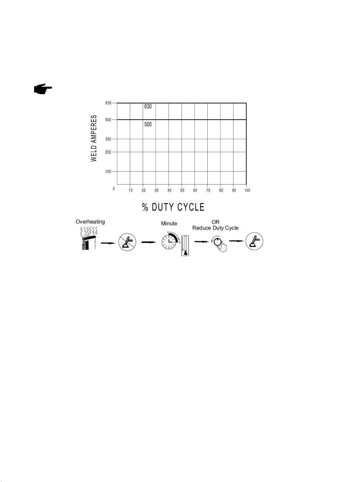
1-4 Duty cycle............................................................................................................................................................ 7
1-5 Applications......................................................................................................................................................... 7
1-6 Warning label...................................................................................................................................................... 8
2-VERSIONS BRIEFS...................................................................................................................................................... 8
3-BEFORE COMMISSIONING........................................................................................................................................9
3-1 Utilization for intended purpose only............................................................................................................... 9
3-2 Machine installation rules.................................................................................................................................. 9
3-3 Power source connection.................................................................................................................................. 9
3-4 Welding cables instruction................................................................................................................................ 9
4-SYSTEM INSTALLATION.......................................................................................................................................... 11
4-1 System components........................................................................................................................................ 11
4-2 Installation......................................................................................................................................................... 11
5-AMIG 500/630 PD........................................................................................................................................................ 14
5-1 Interface............................................................................................................................................................. 14
5-2 Control panel.....................................................................................................................................................15
5-3 Sub menu.......................................................................................................................................................... 19
5-4 Job mode........................................................................................................................................................... 22
5-5 Technical data...................................................................................................................................................24
5-6 Disassembly and reassembly.........................................................................................................................25
6- WIREFEEDER.............................................................................................................................................................27
6-1 Features.............................................................................................................................................................27
6-2 Interface............................................................................................................................................................. 27
6-3 Control panel.....................................................................................................................................................29
6-4 Structure............................................................................................................................................................ 31
6-5 Installation and operation................................................................................................................................ 32
6-6 Technical data...................................................................................................................................................32
6-7 Dimension..........................................................................................................................................................33
6-8 Spare parts........................................................................................................................................................ 33
7-TROUBLE SHOOTING............................................................................................................................................... 35
8 –CARE AND MAINTENANCE................................................................................................................................... 38

6
1-GENERAL REMARKS
1-1 Power source features
This series of power sources apply IGBT soft switch inverter technology. Its internal control system applies DSP which
ensures quick response to any change during the welding process so as to achieve precise control of welding process
and ensure optimal welding results. The strong ability of arc self-adjustment ensures a highly stable welding current
against grid fluctuation and arc length change to get optimal results.
Features and benefits:
- The fully digital MCU+DSP control system realizes precise control of the welding process, stable welding arc, and good
weld formation.
- Equipped with high penetration welding process, which can achieve full penetration of medium and thick plates; reduce
the number of welding layers and improve production efficiency.
- Friendly operation interface, unified adjustment method, easy to master.
- 100 sets of welding procedures can be stored, which facilitates the use of multiple welding specifications at the same
station.
- The special four-step function can reduce the labor intensity of the welder and improve the quality of the weld joint when
welding long welds.
- Double pulse function to obtain beautiful fish-scale weld appearance.
- Powerful protection function, can identify the cause of the alarm through the error code.
1-2 Functional principle
This series of power sources adopt IGBT soft switch inverter technology to improve the dynamic response rate and make
the machines with small size and light weight. The control circuit's closed-loop control makes the power source enjoy
strong ability against power grid fluctuation and perfect welding performance. The schematic diagram is as shown in Fig.
1-2-1:
Fig.1-2-1 Schematic diagram
1-3 Output characteristics
Fig.1-3-1 Output characteristics

7
1-4 Duty cycle
Duty cycle is percentage of 10 minutes that a machine can weld at rated load without overheating. If overheats,
thermostat(s) will open, output stops. Wait for fifteen minutes for the machine to cool down. Reduce amperage or duty
cycle before welding.
Note! Exceeding duty cycle can damage the machine and greatly reduce its lifespan
Fig.1-4-1 Duty cycle
1-5 Applications
This series of machines have many welding processes and can weld most of the metal materials, including carbon steel,
stainless steel, aluminum and Al-Mg alloy, copper and alloy, etc.
Recommended areas of use as follows:
-Coal mining machinery
-Pressure vessel
-Truck modification
-Yacht manufacturing
-Aluminum template, etc.

8
1-6 Warning label
The warning label is affixed on the top of machine.
Fig. 1-6-1 Warning label
2-VERSIONS BRIEFS
Professional welding of special materials requires special welding parameters. Different models of the power sources are
matched to different welding
●AMIG 500/630 PD
This series inverter welding machine is specially designed for pulse MIG welding, Has a greater penetration It has MIG,
Pulse MIG,PD-MIG welding processes.

9
3-BEFORE COMMISSIONING
Warning! Operating the equipment incorrectly can cause serious injury and damage. Do not use the functions
described here until you have read and completely understood “safety rules”.
3-1 Utilization for intended purpose only
The power source may only be used for MIG, P-MIG,PD-MIG. Utilization for other purposes, or in any other manner, shall
be deemed to be "not in accordance with the intended purpose". The manufacturer shall not be liable for any damage
resulting from such improper use.Operate, inspect and maintain should follow all the instructions given in this manual.
3-2 Machine installation rules
According to test, protection degree of this power source is IP23. However, the internal key components must be
protected from direct soaking.
Warning! A machine that topples over or falls from its stand can cause injury. Place equipment on an even,
firm floor in such a way that it stands firmly.
The venting duct is very important for safety protections. When choosing the machine location, make sure it is possible for
the cooling air to freely enter and exit through the louvers on the front and back of machine. Any electro conductive
metallic dust like drillings must not be allowed to get sucked into the machine.
3-3 Power source connection
- The power source is designed to run on the voltage given on the nameplate.
- The mains cables and plugs must be mounted in accordance with the relevant technical standards.
- The power supply sockets that come with power source are designed to use strictly according to the marked voltages.
Note!Inadequately dimensioned electrical installations can lead to serious damage. The mains lead, and its fuse
protection, must be dimensioned in accordance with the local power supply. The technical data shown on the
nameplate shall apply.
3-4 Welding cables instruction
When welding, please pay attention to the followings:
a. The welding cables should be kept as short as possible;
b. If extended cable is used, please do as shown in Fig. 3-4-1.

10
Wrong
Coil the excess ground cable and welding cable in same direction
respectively.
Correct
Straighten the ground cable and welding cable and make them close to
each other.
Bundle the ground cable and welding cable together, running the wires
close to the ground.
Correct
When the excess cables are only be used by rolling up, coil the cables
to two windings in reverse direction and overlap them.
The number of turns for A is same as the number for B.
Handle the welding cable and ground cable according to
above-mentioned method.
Fig. 3-4-1 Welding cables instruction

11
4-SYSTEM INSTALLATION
4-1 System components
This series inverter welding machine is specially designed for working with robot, it needs follow parts to combine robot
welding system.
Fig. 4-1-1 System components
4-2 Installation
●Power supply and cable requirement
Table4-2-1: Power supply and cable requirement
Note! Welding machine must be taken special design if it is powered by generator, please contact with
manufacturer if you have such needs.
Warning! Be careful! Short circuit will cause the risk of personal injury and property loss.
- Operating by professional electrician
- Avoid hot-line work
Model
500
630
Power supply
3 phase,AC380/400/415V±10%, 50/60Hz
Electricity grid min.
power (KVA)
Power grid
31
44
Generator
48
68
Input protection(A)
Fuse
50
70
Circuit breaker
63
80
Cable size (mm²)
Power cord
≥6
≥10
Welding cable
70
95
Protective GND wire
≥6
≥10

12
1.The user should have a corresponding power distribution cabinet
and a corresponding circuit breaker, and its current rating should be
greater than or equal to the rated current specified on the nameplate
of the welding power source;
2.Please connect according to the diagram or other correct way, the
yellow-green wire should be grounded reliably.
Fig. 4-2-1 Connections for power cord and distribution box
● Welding cable connection
1.Plug one end of the ground cable to the output socket (-) of power
source and turn it to fasten it,Connect the other end of the ground
cable to the work piece.
2.Connect the welding power source and the wire feeder with a
control wire.
3.Connect welding power source and wire feeder with welding cable.
4.Connect the water outlet of the water cooler and the wire feeder
with a blue water pipe
5.Connect the water inlet of the water cooler and the wire feeder with
a red water pipe
Fig. 4-2-2 Welding cable installation

13
●Gas cylinder installation
Warning! The falling of the gas cylinder will bring the risk of personal injury and property damage.
1. Place the gas cylinder in a flat place and fix it.
2.Remove the protective cap of the cylinder.
3.Open the cylinder valve and close it immediately to blow off all dust.
4.Tighten the gas meter to the gas cylinder.
5.Use a gas pipe to connect the protective gas hose to the gas meter;
the recommended gas flow is 15 ~ 20L / min.
6.Connect the gas meter heating device cable to the heating power
output socket on the rear panel .
Fig. 4-2-3 Gas cylinder installation
●Torch installation
1. Connect the tail of the torch to the welding torch interface of the
wire feeder.
2.Connect the red water hose of the torch to the red water port of the
wire feeder
3.Connect the blue water hose of the torch to the blue water port of
the wire feeder
Fig. 4-2-6 Torch installation

14
5-AMIG 500/630 PD
5-1 Interface
Fig. 5-1-1 Front panel
1. Control panel
2. Quick socket (-)
For connecting with the work piece by ground cable.
3.control socket
Reserved.
4.Circuit breaker
The function of circuit breaker is to protect welding machine and operator by automatic trip to turn-off power supply when
overload or short circuit happens to the power source. Normally, the switch flipped to upward means power- on. To start or
stop the welding machine is done by the mains switch in the distribution box. Please do not take this circuit breaker as the
power switch.
5.Fuse
6.Power supply cable
Yellow-green cable needs to be grounded firmly; other 3 cables connect with three phase power.
7.Fan
8.Quick socket +
Connect with wire feeder by wire feeder cable.
9.Power supply socket for gas heater(AC36V)
For connecting the heater coil of the CO2 gas regulator.
10.Nameplate
11.Wire feeder over load protector
This protector will turnoff (jump up) automatically when wire feeder is in fault, such as over load. Press this protector after
trouble shooting.
12. Wire feeder control socket X7
For connecting with the wire feeder.
Fig. 5-1-2 Rear panel
Fig. 4-3-2:Rear panel

15
5-2 Control panel
The functions on the control panels are all arranged in a very logical way. The various modes and parameters needed for
welding are easy to select by pressing the appropriate button; parameters are easy to be adjusted by rotating encoder.
Synergic adjustment makes the complicated operation much easier.
Note! Some described parameters in this manual may be slightly different from the power source, some
identification may be slightly different from power source identification, but the manner of working is the same.
Warning! Operating the equipment incorrectly can cause serious injury and damage. Do not use the functions
described here until you have read and completely understood all content of this manual.
Note! Control panel of welding machine is for function selection and some parameters setting.
Fig. 5-2-1 Control panel
(1) Adjustment knob
Adjust the parameters. When the light is on, this knob can be used to adjust parameters of selected item.
Reset:Press adjustment knob (1) for about 5 seconds, it comes back to factory set.
Important! Values increase in clockwise direction while values decrease in anti-clockwise rotation. To turn the knob left or
right while pressing it will achieve quick adjustment.
(2) Parameters selection button F2
Press this button, one parameter indicator light is on, the corresponding parameter is chosen; keep pressing this button
can switch among the following parameters:
- Arc length adjustment
- Welding voltage
- Job (Channel) No.
If both the indicators of parameter selection button and the adjustment knob (1) are on, the indicated/ selected parameter
can be adjusted with the knob (1).
(3) Parameters selection button F1
Press this button, one parameter indicator light is on and the corresponding parameter is chosen; keep pressing this
button can switch among the following parameters:
- Welding current

16
- Wire speed
- Arc force/ Arc stiffness
Important!On Panel control mode, press F1 to choose one of the above parameters, and value of the parameter can be
adjusted by the knob (1).
(4) CALL button
Load stored set of parameters.
(5) STORE button
- For accessing the sub-menu parameter set-up menu or (in job mode) for storing parameter settings.
- During creating or correcting a job, store parameter settings.
(6) Wire diameter button
Select the diameter of the welding wire. D0.8 and D1.0 are the diameters of the welding wire displayed when tandem
double-wire welding. D0.8 and D1.0 represent the welding wire with a double-wire 0.8 diameter and a double-wire 1.0
diameter, respectively.
When using the tandem double-wire function, you need to adjust the sub-menu parameter "P21 double-wire master-slave
control" to ONd.
Operation method:
1. Press the "Save" + "Wire Diameter" buttons at the same time to enter the sub menu.
2. Press the "Wire Diameter" button until the left display shows P21.
3. Adjust the knob to make the P21 parameter value “ONd”, and click the "Save" button to exit.
At this time, the D0.8 indicator on the panel flashes, which means it enters the double wire 0.8 welding wire welding mode.
Continue to press the "Wire Diameter" key to switch to the dual 1.0 mode.
4. Follow step 1 again to enter the hidden parameters, adjust the "P21 double-wire master-slave control" parameter value
to ON, and exit the tandem double-wire welding mode.
(7) Wire material selection button(s)
For selecting the filler metal and shielding gas type. OP is used for upgrade.
(8) Torch operation modes button(s)
For selecting the operating mode of the torch.
- 2-step mode
- 4-step mode
- Special 4-step mode
- Spot welding mode
Operating mode of torch
Graphic symbol
Fig. 5-2-2 Press torch trigger Fig.5-2-3 Hold torch trigger Fig. Fig.5-2-4 Release torch trigger
P03……Pre-gas time
I………..Welding current: Uniform thermal input for the preheated base metals.
P08……Spot welding time
P04……Post-gas time
P01……Burn back time

17
- 2-step mode
Fig. 5-2-5 2-step mode
- 4-step mode
Fig. 5-2-6: 4-step mode
- Special 4-step mode (initial parameters and crater filler parameters are adjustable)
Fig. 5-2-7: Special 4-step mode
- Spot welding mode
Fig. 5-2-6 Spot welding mode

18
(9) Process button
For select welding process.
- P-MIG
- PD-MIG
- MIG
- STICK
- TIG
(10) F2 selection button indicator
When the indicator lights up, F2 button works.
(11) “JOB” No.
For receiving parameter records/job numbers that were previously saved with “Store” button.
(12) Welding speed indicator
When the light is on, the right displayer shows the preset welding speed (cm/min) , and the wire speed and welding
current & voltage are calculated as a function of the “a”-dimension parameter (20)
(13) Welding voltage indicator
When the indicator lights up, the right displayer shows the preset or actual welding voltage.
Important! Power source open circuit voltage is variable. In STICK mode, open circuit voltage displayed is about 23V
before welding; after starting arc, it increases as the real situation, and may be up to 106V, so as to get ideal arcing
characteristic.
(14) Arc-length correction parameter
For correcting the arc length (-5.0-+5.0) by adjustment knob (1) when indicator is on, the right displayer shows the arc
length value when the indicator lights up.
- shorter arc length
0 neutral arc length
+ longer arc length
Important!The range (-5.0-+5.0) means that, when preset welding current, the arc length value is -50%~+50%of the
corresponding welding voltage.
(15) Temperature Indicator
When the temperature inside the machine is too high, the indicator light is on and the welding machine stops working.
(16) Arc force/ Arc stiffness
For adjusting the peak current during the P-MIG/PD-MIG/MAG welding process, values range (-5.0-+5.0)
- shorter arc length
0 neutral arc length
+ longer arc length
For synergic MIG, the inductance value when changing short circuiting transfer (-5.0-+5.0).
- harder, stable arc
0 neutral arc
+ soft, low spatter arc
(17) Wire feeding speed indicator
When the indicator is on, the left displayer shows the wire feeding speed (M/min), when adjust this button, the relevant
parameters will change automatically
(18) Welding current indicator
When the indicator is on, the left displayer shows the preset or real welding current values
(19) Sheet thickness indicator
When the indicator is on, the left displayer shows the preset sheet thickness (mm). The relevant parameters will change
automatically when this value is changed.
(20) “a” dimension indicator
When the indicator is on, the left displayer shows “a” dimension (mm). Wire speed and welding current & voltage are
calculated as a function of the “a”-dimension parameter
(21) F1 selection button indicator
When the indicator lights up, F1 button works.

19
(22) CALL program mode indicator
When the indicator is on, power source is in call program mode.
(23) Submenu parameters regulation indicator
This indicator is on when in sub menu parameters adjustment.
5-3 Sub menu
Sub-menu parameter
In order to achieve an optimum welding result, it is necessary in some cases to make corrections of the arc-length, arc
force as well as parameters like pre-gas time, post-gas time and slow wire feeding. For details of how to set the Sub-menu
parameters, please refer to “Sub-menu parameter set”. Specific sub-menu parameters as Table 5-3-1:
Item
Parameters
Setting Range
Min. Value
Factory Setting
P01
Burn back time
0.01~2.00s
0.01s
0.08s
P02
Slow wire feeding
1.0~22.0M/min
0.1 M/min
3M/min
P03
Gas pre-flow time
0.1~10.0s
0.1s
0.20s
P04
Gas post-flow time
0.1~10.0s/ON
0.1s
1.0s
P05
Initial period
1~200%
1%
135%
P06
Crater filler period
1~200%
1%
50%
P07
Transitional period
0.1~10.0s
0.1s
0.2s
P08
Spot welding time
0.01~9.99s
0.01s
2.0s
P09
Digital/Analog control
OFF/ON
――
OFF
P10
Water cooling selection
OFF/ON/ONo
――
ON
P11
Double pulse frequency
OFF/0.5~5.0Hz
0.1Hz
OFF
P12
High pulse group arc length
adjustment
-5.0~+5.0
0.1
0
P13
Double pulse speed offset
0.0~2.0m
0.1m
2.0m
P14
High pulse group duty cycle
10~90%
1%
50%
P15
Pulse mode
OFF/UI/II/UU
――
OFF
P16
Fan-on demand cooling time
5~15min
5min
5min
P17
Special 2-step arc start time
OFF/0~10.0s
0.1s
OFF
P18
Special 2-step arc stop time
OFF/0~10.0s
0.1s
OFF
P19
Separate adjustment mode
OFF/ON
――
OFF
P20
Phase angle of double wire
0~100%
1%
0
P21 *1
Master and slave
ONd/ONL/ONT/OFF
--
OFF
This manual suits for next models
2
Table of contents