Marshall Excelsior MER470 STANDARD KIT User manual

IMPORTANT INSTALLATION INSTRUCTIONS
FOR FLOW-LONGER PROPANE KITS
MER470 STANDARD KIT
MER471 PLUS KIT
LP-Gas demands respect and understanding if it is to be used safely. It is important to read all instructionsbefore
installing your kit. Please observe all cautions and warnings that we have given throughout these instructions.
They are for your safety.
The Flow-Longer LP-Gas Line Tap Kit makes it possible to connect small, portable appliances, normally fueled
by disposable LP-Gas cylinders, to the existing LP-Gas fuel supply of a recreational vehicle, cottage, back yard
patio, etc. without interrupting the supply of regulated fuel to the system. Flow-Longer eliminates the need to
purchase an extra LP-Gas cylinder or several small, disposable-type cylinders. The MER470 Flow-Longer kit
includes one (ME415) brass tee and one (MER421-144) 12 foot high pressure appliance hose. The tee fitting must
beinstalledbetweenthevaporwithdrawalvalve on yourLP-Gascontainerandthe pressureregulator.Thisproperly
places the tee fitting in the high-pressure portion of the LP-Gas system. Gas connections to the tee fitting are not
designed for movement or rotation after installation. Flexing, twisting, or vibration should be avoided.
The Flow-Longer tee contains a flow limiting feature designed to reduce the flow of gas should it detect an excess
flow condition in the system. This device may activate each time you open the cylinder valve. Follow the general
lighting instructions herein, to allow this flow limiting device to properly reset.
CAUTION: The Flow-Longer tee and associated hose assembly are intended for outdoor use only,with approved
DOT cylinders or ASME tanks with a 350 psi pressure relief valve. These components must only be connected to
cylinder valves supplying LP-Gas vapor. DO NOT connect to any valve delivering liquid propane. DO NOT allow
cylinders to lie on their side or become physically oriented in such a manner as to allow liquid propane to be
withdrawn. DO NOT attempt to transfer liquid propane through Flow-Longer hose or fittings to fill any LP-Gas
container.
WARNING: LP-Gas is flammable, under pressure, and can freeze skin. Liquid propane introduced into the Flow-
Longer components, or a pressure regulator would result in damage to both the regulator and the gas appliance
controls. Failure to follow these instructions could result in a LP-Gas leak, which if ignited, could result in fire,
explosion, severe personal injury, property damage or death.
INSTALLATION PROCEDURE:
1)
Turn off all appliances connected to the existing LP-Gas system.
2)
Close the vapor withdrawal valve at the cylinder (clockwise rotations). If your LP-Gas system is a double
cylinder installation, turn both cylinders off. (See note on following page regarding double cylinder
installations.)
3)
Witha 7/8 inch open end wrench, unthread the brass POLnut that connects the propane vapor withdrawal
valve to the pressure regulator or pigtail hose. This is a left-hand threaded connection, so turn the brass
nut clockwise to loosen.
Marshall Excelsior Co.
1506 George Brown Drive Marshall, MI 49068
Phone (269) 789-6700 Fax (269) 781-8340
www.marshallexcelsior.com
WARNING:These products contain a chemical known to the state of
California to cause cancer and birth defects or reproductive harm

4)
It will be necessary to move the existing POL fitting on your regulator away from the vapor withdrawal
valve far enough to place the Flow-Longer tee between them. If the Flow-Longer is being installed on
an RV’s ASME tank, this may also require moving the regulator cover.
5)
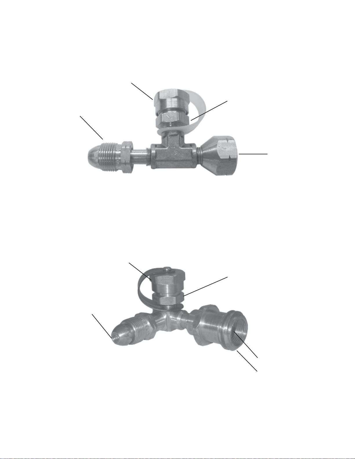
Thread the male POL fitting on the Flow-Longer tee, into the vapor withdrawal valve. Turn this left-
hand nut counter-clockwise to tighten, but before tightening, position the fitting’s top outlet port for best
access. Use a 7/8 inch wrench to tighten the POL nut into the vapor withdrawal valve.
6)
Flow Longer Tee- Thread the male POL fitting attached to the pressure regulator or pigtail hose, into the
female POL fitting on the Flow-Longer tee.Again, turn the left-hand POL nut counter-clockwise. Two
(2) wrenches are required to tighten this connection properly, but before tightening, besure to orient your
pressure regulator in its original position. It is important not to break the factory seal on the threaded inlet
and outlet connections on the Flow-Longer tee. Use one wrench to securely hold the Flow-Longer
female fitting while tightening the male POL nut with a second wrench. Prevent rotating the Flow-
Longer tee while tightening this connection.
Flow Longer Plus Tee–Can follow same installation instructions as above orcan be used with a standard
Type I connection, by turning the plastic nut onto the male threads clockwise until hand tight. Do not use
tools to make this connection.
7)
If you installed the Flow-Longer tee on an RV’s ASME tank, securely fasten the pressure regulator and
its accompanying low-pressure outlet hose to the vehicle, to avoid possible damage or loosening due to
“over the road” vibration. Depending upon the particular layout of your vehicle’s LP-Gas container
compartment, it may be necessary to have an LP-Gas dealer or RV service technician fabricatebrackets
or supporting hardware.
LEAKAGE CHECKS for the Flow-Longer tee:
After allconnections are tightened securely,the installation must bechecked for leaks.Make sure all gas appliances
are off, and then turn the LP-Gas vapor withdrawal valve counter-clockwise to its full open position. Using an
ammonia-free soap, prepare a soapy water solution and check for leakage at all the connections from the valve up
to and including the low-pressure outlet of the regulator. If a leak is found at one of the POL connections, tighten
it until the bubbles stop. If however, leakage is found at a pipe thread connection at the Flow-Longer tee, or at the
pressure regulator, close the cylinder valve immediately and contact your LP-Gas dealer.
WARNING: An LP-Gas leak, if ignited, could result in fire, explosion, severe personal injury, property damage,
or death. Matches, candles, or other sources of open flame must NEVER be used to test for leaks.
DOUBLE CYLINDER INSTALLATIONS:
If your double cylinder installation has an automatic changeover regulator, the indicator arrow of the
changeover must point at the cylinder to which the tee is connected to assure an uninterrupted supply of gas
to the tee.As long as there is gas in the cylinder to which the tee is connected, the tee will function regardless
of which cylinder the arrow points to. However, if the cylinder to which the tee is connected is emptied, the
automatic regulator will not allow gas to flow to the tee if the arrow points to the opposite cylinder. If the
cylinder to which the tee is connected is empty and the arrow is pointed to the empty cylinder, the gas
pressure to the tee will be reduced to approximately 10 to 15 psi. While this pressure is sufficient for most
portable appliances, it may not be suitable for appliances having larger BTU requirements. Also, some
regulatorsonportableappliancesfunctiondifferentlywithlessthanfullcylinderpressure.Anemptycylinder
Page 2

should be filled as soon as possible to assure safe and efficient operation of appliances connected to the
Flow-Longer tee.
If your double cylinder installation has a manual changeover regulator with a tee check in the inlet; Flow-
Longer will not function when the cylinder to which it is connected is empty, or if the cylinder’s valve is
turned off.
CONNECTINGHIGH-PRESSURE LP-GASAPPLIANCES:
CAUTION: Portable heaters, lanterns, stoves, and grills are for outdoor use only. Use only the Marshall Excelsior
MER421-144 (12 foot) or MER421-60 (6 foot) high-pressure appliance hose. Connect only to appliances designed
for high-pressure LP-Gas vapor. These appliances have a female threaded inlet that mates with small throw-away
1 lb. cylinders. This is the same inlet connection that the appliance hose threads into.
WARNING: Use of hoses other than the high-pressure appliance hoses specified may cause component failure
and LP-Gas leaks, which if ignited, could result in fire, explosion, severe personal injury, property damage, or
death.
1) Turn the portable appliance gas valve off and thread the male end ofthe appliance hose into the appliance
connection. (standard right-hand thread.) No tools are required for this connection. Hand tighten only.
2) Remove the protective brass cap from the tee fitting and thread in the female end of the appliance hose.
No tools are required for this connection. Hand tighten only.
LEAKAGE CHECKS for the appliance hose:
The Flow-Longer tee and appliance end fitting of the hose are equipped with O-Ring seals. After the appliance
hose is installed, both end connections must be checked for leaks. Make sure the gas appliance is off, and then turn
the LP-Gas vapor withdrawal valve counter-clockwise to its full open position. Using an ammonia-free soap,
prepare a soapy water solution and check the hose connections for leakage at the appliance and the Flow-Longer
tee.If aleakisfoundateitherconnection,an O-Ringmayhavebeendamaged.Closethecylindervalve immediately
and contact your LP-Gas dealer.
3) Light appliance according to the manufacturer’s instructions.
TO DISCONNECT APPLIANCEHOSE:
WARNING: Make sure there are no open flames or other sources of ignition near the appliance hose while
disconnecting. LP-Gas pressurized within this hose during use is flammable and if ignited, could result in fire,
explosion, severe personal injury, property damage, or death.
1)
Turn appliance off.
2)
Unthread hose at tee fitting end, (not at appliance end) and replace the brass protective cap. Come LP-Gas will escape
from this exposed end of the hose, so be sure to keep it away from flames or any source of ignition.
3)
Disconnect hose from appliance
4)
Coil the hose and thread the ends together for protection during storage.
Page 3

Flow-Longer Tee
Protective Cap
High Pressure Appliance
Outlet
POL End
Inlet
Female POL End
Outlet
Flow-Longer Plus Tee
Protective Cap
High Pressure Appliance
Outlet
POL End
Inlet
Female POL End/
Type I Male Acme
Outlet
The contents of this publication are for informational purposes only. While every effort has been made to ensure accuracy, these contents are not to be construed as warranties
or guarantees, expressed or implied, regarding the products or services described herein or for their use or applicability. Marshall Excelsior Co. reserves the right to modify or
improve the designs or specifications of such products at any time without notice. The MEC logo is the trademark of Marshall Excelsior Co.
TM
Page 4
Instruction #429 Rev-B
This manual suits for next models
1
Table of contents
Other Marshall Excelsior Industrial Equipment manuals