Amkus AMK-100R Guide

©Copyright Amkus Rescue Systems, Inc. 2016 LAR-001 May 31, 2016 Rev00
DANGER Understand manual before use. Operating AMKUS Rescue Systems without understanding
the manual, receiving proper training, and using appropriate personal protective equipment is
a misuse of AMKUS equipment. This manual does not fully address safety. Additional safety
information is published in AMKUS Safety Manual LAA-001. Obtain safety information at
www.amkus.com/
©Copyright Amkus Rescue Systems, Inc. 2016 LAA-001 April 15, 2016 Rev00
DANGER Understand manual before use. Operating AMKUS Rescue Systems without understanding the
manual, receiving proper training, and using appropriate personal protective equipment is a
misuse of AMKUS equipment. Obtain safety information at www.amkus.com/
This Safety Manual is intended to familiarize rescue workers and maintenance personnel with the safety messages of AMKUS
Rescue Systems, including powered rescue tools (rams, cutters, spreaders, combination tools), power units (electric or gasoline
driven), and powered rescue tool components (cable assemblies, hose assemblies, hose reels, etc.). The safety messages in this
publication supersede safety information appearing in AMKUS publications prior to April 2016.
This manual is intended for use with manuals published by manufacturers of prime movers (engines, electric motors, and pumps)
used in AMKUS power units.
This manual does NOT address operation or servicing of AMKUS Rescue Systems. Only competent rescue tool repair technicians
are quali¿ ed to repair AMKUS equipment. This manual should be available to all personnel involved with AMKUS equipment.
SAFETY MANUAL for AMKUS
RESCUE SYSTEMS
AMKUS RESCUE SYSTEMS
www.amkus.com 4201 Montdale Drive, Valparaiso, IN 46383-4098 USA
800-592-6587 • 219-548-5000 • Fax 630-515-8866
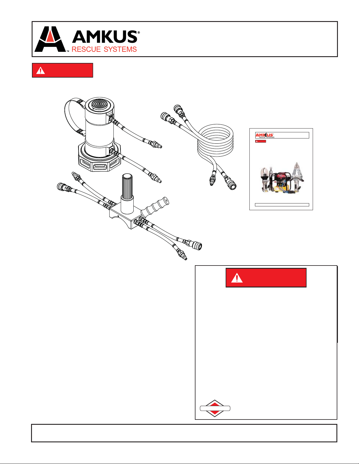
AMK-100R LIFTING JACK
User Information Manual
AMKUS RESCUE SYSTEMS
www.amkus.com 4201 Montdale Drive, Valparaiso, IN 46383-4098 USA
800-592-6587 • 219-548-5000 • Fax 219-476-1669
DANGER
PERSONAL RESPONSIBILITY CODE
The member companies of FEMSA that provide emergency response
equipment and services want responders to know and understand the
following:
1. Firefi ghting and Emergency Response are inherently dangerous activities
requiring proper training in their hazards and the use of extreme caution
at all times.
2. It is your responsibility to read and understand any user’s instructions,
including purpose and limitations, provided with any piece of equipment
you may be called upon to use.
3. It is your responsibility to know that you have been properly trained in
Firefi ghting and /or Emergency Response and in the use, precautions, and
care of any equipment you may be called upon to use.
4. It is your responsibility to be in proper physical condition and to maintain
the personal skill level required to operate any equipment you may be
called upon to use.
5. It is your responsibility to know that your equipment is in operable
condition and has been maintained in accordance with the manufacturer’s
instructions.
6. Failure to follow these guidelines may result in death, burns or other
severe injury.
FEMSA
Fire and Emergency Manufacturers and Service Association
P.O. Box 147, Lynnfi eld, MA 01940 • www.FEMSA.org
Thank you for choosing AMKUS Rescue Systems. Read this User
Information Manual thoroughly. If you have any questions, please
contact your local dealer or AMKUS Rescue Systems.
Please complete the tool registration form included with your
equipment and return it to AMKUS Rescue Systems. You may also
register your equipment on-line at www.amkus.com.
The serial number for your tool is identifi ed on the product label
which is located on the cylinder of the tool. Please have the
serial number available if you need to contact your local dealer or
AMKUS Rescue Systems.

©Copyright Amkus Rescue Systems, Inc. 2016 LAR-001 May 31, 2016 Rev00
2
1.0 MEANING OF SAFETY SIGNAL WORDS
A safety related message is identifi ed by a safety alert symbol and a signal word to indicate the level of risk involved with a particular
hazard. Per ANSI standard Z535.6-2011, the defi nitions of the four signal words are as follows:
DANGER DANGER indicates a hazardous situation which, if not avoided, will result in death or serious
injury.
WARNING WARNING indicates a hazardous situation which, if not avoided, could result in death or serious
injury.
CAUTION CAUTION indicates a potentially hazardous situation which, if not avoided, could result in minor
or moderate injury.
NOTICE NOTICE is used to address practices not related to physical injury.
2.0 SPECIFICATIONS
Lifting Capacity 50 tons (45 metric tons)
Stroke 6” (152mm)
Collapsed Height 10” (254mm)
Extended Height 16” (406mm)
Interlocking Shim Plates 1” 2” 3” (25mm, 50mm, 75mm)
Remote Operated Valve With Extension Hose 10’ (3m)
Maximum Operating Pressure 10,500 psi (724 bar)
Weight of Jack 20.1 lbs (9.1kg)
Operating Temperature Range -25 to 140 deg. F (-32 to 60 deg. C)
Hydraulic Fluid AMKUS MV1
Safety Data Sheet (SDS) for AMKUS MV1 Hydraulic Fluid is available
at AMKUS.com and CHEMTREC.com
AMK-100R Cylinder Body Including 1” Shim Including 2” Shim Including 3” Shim
Width X Depth 6.0” X 10.0”
151 X 255 mm 7.9” X 11.0”
200 X 280 mm 7.9” X 12.0”
200 X 306 mm 7.9” X 13.0”
200 X 331 mm
Length Closed 10.0” (255 mm) 11.0” (280 mm) 12.0” (306 mm) 13.0 (331 mm)
Length Open 15.9” (404 mm) 16.9” (429 mm) 17.9” (454 mm) 18.9” (480 mm)
Weight
(Lifting Jack Cylinder and Shim)
20.1 lbs (9.1 kg) 24.3 lbs (10.9 kg) 27.9 lbs (12.6 kg) 30.8 lbs (13.9 kg)
3.0 OPERATING INSTRUCTIONS
Amkus 50t Lifting Jack includes a 50t lifting cylinder, a remote control valve, a 10’ (3m) black and yellow extension hose, and three
stacking shims 1” (25 mm), 2” (50 mm), and 3” (75 mm).
The lifting jack includes a remotely operated control valve so lifting jack may be operated from a location outside the crush zone.
Select a position to place the lifting jack which can fully support the load. Support on soft ground can be increased with cribbing and
support plates. Potential for loads sliding sideways is reduced by avoiding metal-to metal contact when supporting the load.
Interconnect the hoses to the jack, remote control valve, and power unit. Start the power unit and retract the jack to the fully closed
position. Take up space between the jack and the load by adding interlocking spacers supplied with the jack or by cribbing to
minimize the lifting required.
Identify the crush zone. These are areas under the load and around the load with risk of crushing from a falling or rolling load. Select
a position outside the crush zone from which to operate the lifting jack.
Extend the lifting head to the object being displaced. Insure nearby people are clear of the crush zone before lifting or retracting.
Displace the object only as far as needed. Stop to stabilize the load in increments as the load is lifted or lowered. All AMKUS rescue
tools are equipped with a twist grip control valve. The 100k Lifting Jack performs only lifting operations. Do not attempt to pull using
the equipment. Rotating the control valve counter clock wise retracts the piston. Rotating the control valve clock wise extends the
jack’s piston. The control valve is equipped with a deadman safety feature, which causes the handgrip to return to the center (neutral)
position when it is released. The movement of the tool will stop. The tool will continue to contain the internal pressure that was
present at the time the control valve handgrip was released.

©Copyright Amkus Rescue Systems, Inc. 2016 LAR-001 May 31, 2016 Rev00
3
WARNING Loads supported by lifting jacks present a crushing hazard to people under or near the load.
Reduce crush hazard by insuring people and equipment remain out of the crush zone during
lifting and retracting operations.
As the lifting jack extends, the angle of the lifting head may change in relation to the object being displaced. If this movement places
you or others in jeopardy, you should immediately release the control valve handgrip. The deadman safety feature of the control valve
will return the handgrip to the center (neutral) position, and the movement of the lifting jack will stop.
NOTICE The minimum safe bend radius of the hydraulic hoses is 4 inches (101.6 mm).
4.0 ROUTINE MAINTENANCE
WARNING Avoid contact with escaping hydraulic fl uid under pressure. If hydraulic fl uid punctures skin,
seek medical treatment immediately. Contact with escaping hydraulic fl uid under pressure could
result in serous injury or death.
Inspect all hose, hose fi ttings and couplings for leakage and damage (see routine maintenance for hoses and couplings). Periodically
inspect all hydraulic fi ttings for tightness. Clean excess dirt away from the area where the rod reenters the cylinder.
Periodically check the 100k Lifting Jack for leakage, damage to the cylinder body, damage to the piston, damage to the pads, loose or
missing screws, and loose coupling connections. Because the cylinder rod is lubricated by the hydraulic fl uid and wiped clean using
a unique T-seal O-ring, no lubrication is necessary for the AMKUS hydraulic lifting jacks.
4.1 ROUTINE MAINTENANCE FOR HOSES
• Always disconnect the hoses at the control valve fi rst before disconnecting the provided extension hoses from the lifting jack.
• After each use, hoses should be wiped clean with a light cleaning solvent such as Simple Green®.
• Inspect hoses for damage to the rubber outer cover. (Damage which exposes the wire braided reinforcement subjects the wire to
corrosion and may weaken the hose.)
• Damaged hoses should be replaced before use.
4.2 ROUTINE MAINTENANCE FOR COUPLINGS
WARNING Damaged couplings should be replaced immediately. Damaged damaged could cause hydraulic
fl uid to escape under high pressure. Contact with escaping hydraulic fl uid under pressure could
result in serious injury or death. Loss of hydraulic pressure prevents the rescue tool from operating
properly and may result in serious injury or death.
• Couplings should be kept free of dirt and contaminants. (They may be most easily cleaned by immersing in, or scrubbing with, a
petroleum based solvent such as SAFE- SOL® 140.)
• Couplings should then be lubricated with a non-water based lubricant such as WD-40®.
• The rubber dust caps which are provided with the tools should also be cleaned periodically. (Be aware that while the couplings may
be clean, the dust caps will accumulate dirt during use.)
• Do not cover a clean coupling with a dirty dust cap.
4.3 MAINTENANCE RECORDS
It is a user’s responsibility to keep maintenance records for each component of the rescue system. Maintenance shall be performed
in accordance with the recommendations as outlined in this manual.
5.0 PROTECTIVE CLOTHING
It is the responsibility of the user to insure that appropriate protective clothing and equipment are used to provide protection from
those hazards to which personnel are exposed or could be exposed while working with this product.
6.0 TRAINING
This product is designed to be used by emergency services personnel to facilitate the extrication of victims from entrapment. Its use
should be limited to trained personnel only. All personnel using this equipment are assumed to have completed a course of instruction
acknowledged as being educationally sound by the local authority having jurisdiction over such training. This document contains
basic operating and maintenance instructions only.

©Copyright Amkus Rescue Systems, Inc. 2016 LAR-001 May 31, 2016 Rev00
4
7.0 SET-UP PROCEDURE
AMKUS equipment is manufactured with superior craftsmanship and quality backed by a factory warranty.
NOTICE Only use AMKUS tools with AMKUS equipment. Mixing AMKUS tools with another manufacturer’s
equipment may cause operational problems, equipment failure, or denial of warranty claims.
NOTICE Only use AMKUS MV1 hydraulic fl uid in AMKUS equipment. Using another manufacturer’s
hydraulic fl uid in AMKUS equipment may cause operational problems, equipment failure, or
denial of warranty claims.
Normally, AMKUS equipment is prepared and serviced by your dealer prior to delivery. If, however, you have decided to place the
equipment into service yourself, please review the following instructions carefully.
1. Remove equipment from the packing cartons and care- fully inspect for damage. Damage that occurs during shipment should be
reported immediately to the carrier.
2. Connect the tool connection hoses to the hose lines from the AMKUS hydraulic power unit.
a. If you have Standard Couplings: Please note that the male and female couplings on the hose lines leading from the power unit
should be connected to the corresponding male and female couplings on the tool connection hoses. To connect the couplings,
twist the sleeve on the female coupling so that the notch in the sleeve lines up with the pin. Push the sleeve back so the pin fi ts
into the notch. While holding the sleeve back, push the male coupling into the female coupling. Release the sleeve; it will spring
forward into place. Twist the sleeve 1/4 turn so that the pin no longer lines up with the notch. Pull on the couplings to check that
they are securely connected.
b1. If you have Mono Couplings: Please note that the female coupling on the hose lines leading from the power unit should
be connected to the corresponding male coupling on the tool connection hoses. To connect the couplings, place the male
coupling into the female coupling. Rotate clockwise until you feel the coupling latch. Pull on the couplings to check that they
are securely connected.
b2. In most cases, the Mono Couplings can be connected and disconnected while the hose line is under fl ow. It is usually not
necessary to place the directional control of the power unit in the neutral position before connecting and disconnecting.
However, certain circumstances such as back pressure in the return line and/or cold temperatures, may make connecting and
disconnecting under fl ow extremely diffi cult or impossible. If you are unable to connect and disconnect while the line is under
fl ow, place the directional control valve of the power unit in the neutral position and then disconnect or connect.
8.0 GETTING STARTED
Connect the hydraulic hoses as directed above matching hose color to hose color. Start the power unit (refer to power unit and engine
manuals). Following the instructions in the power unit manual, operate the selector valve to charge the hose line to which the tool is
connected.

©Copyright Amkus Rescue Systems, Inc. 2016 LAR-001 May 31, 2016 Rev00
5
9.0 DRAWINGS AND PARTS LISTS
12
11
10
1
2
3
4
5
6
15
14
13
789
723 9
13
1716 16 18 19 20
14
21
22
Cylinder Body

©Copyright Amkus Rescue Systems, Inc. 2016 LAR-001 May 31, 2016 Rev00
6
9.0 DRAWINGS AND PARTS LISTS
Cylinder Body
ITEM DESCRIPTION QTY PART #
1ROD T-SEAL - T-SEAL TR031 P/N TSR-333 1 KD0004
2CYLINDER PLUG 1 KR0101
3BACKUP RING-237 TEFLON 1 VOB-237T
4VO-237 1 O-RING-237
5PISTON ROD 1 KR0102
6T-SEAL PISTON SEALTP-035 (TSP-338) 1 KR0108
7ADAPTER 9/16-18 ORB (M) X 9/16-18 ORB(M) 2 KHC0029
8HOSE PUMP SINGLE 9"YELLOW 5FJ-6OR 1 KHPY-0009
9STD CPLFD35(M) X 9/16 ORB(F) (6OR GOLD) 2 KHC002
10 M5X0.8-16 FLAT HEAD CAP SCREW 3 VTM5B0.8FH16
11 WEAR PLATE 1 KR0104
12 CYLINDER BODY 1 KR0100
13 CIRCLE COTTER 2 U182
14 CARRYING STRAP 4 AY303
15 M6-1.0 X 12MM CONE POINT SOCKETSET SCREW 1 VTM6-1.0CP12
16 5/32 X 1-3/4 HD SPIROLPIN 2 VP156X1.75HD
17 3" SHIM PLATE 1 KR0107
18 2" SHIM PLATE 1 KR0106
19 5/32 X 7/8 HDP SPIROLPIN 1 V1900
20 1" SHIM PLATE 1 KR0105
21 DUST CAP 2 KHC006
22 SHOULDER STRAP 1 U150
23 HOSE PUMP 9” BLACK 5FJ-6OR 2 KHP0-0009

©Copyright Amkus Rescue Systems, Inc. 2016 LAR-001 May 31, 2016 Rev00
7
9.0 DRAWINGS AND PARTS LISTS
612 310 987321
6
2
3
5
4
A
3
2
1
6
6
11
6
1
13
Remote Manifold
ITEM DESCRIPTION QTY PART #
1STD CPLFD35(M) X 9/16 ORB(F) (6OR GOLD) 3 KHC002
2HOSE PUMP SINGLE 9" BLK 5FJ-6OR 3 KHP0-0009
3ADAPTER 9/16-18 ORB (M) X 9/16-18 ORB(M) 4 KHC0029
4REMOTE MANIFOLD 1 KV0006
5HANDLE TOP 1 XX625
6STD CPLG FD35(F) X 9/16 ORB(F) (6OR) 5 KHC003
7M6-1 X 25 MM SOCKET HEAD CAPSCREW 4 VTM6C1.0SH25
83/8-16 X 1-1/2 SOCKET HEAD CAPSCREW 1 VT37-16SH1.5
9BALL4MM GRADE 25 CHROME 1 VB4MMCH
10 M5-0.8 X 8MM SOCKET SETSCREW 1 VTM5G0.8SS8
11 HOSEASSY TWIN 120"YEL-BLK 6OR-6OR 1 KHE0Y-0120
12 HOSE PUMP 9”YELLOW 5FJ-6OR 2 KHPY-0009
13 DUST CAP 8 KHC006

©Copyright Amkus Rescue Systems, Inc. 2016 LAR-001 May 31, 2016 Rev00
AMKUS RESCUE SYSTEMS
www.amkus.com 4201 Montdale Drive, Valparaiso, IN 46383-4098 USA
800-592-6587 • 219-548-5000 • Fax 219-476-1669
10.0 TROUBLE SHOOTING GUIDE
PROBLEM SOLUTION
Lifting Jack Does Not Extend Check to see that hoses are properly connected.
Check hydraulic fl uid level in power unit reservoir.
Check to see that the power unit is running.
Check to see that the line is charged.
Tool lacks power or speed Check hydraulic fl uid level in power unit reservoir.
Tool lacks power or speed Check tightness of hose fi ttings.
Replace damaged hoses.
11.0 GENERAL MAINTENANCE AND STORAGE
1. Always store the tool in a clean dry space.
2. Never store a tool under pressure.
3. Store jacks in a slightly extended position.
After each use:
1. Check to see that important tool markings are legible.
Contact your local dealer or AMKUS Rescue Systems for replacement labels.
2. Wipe tool, hoses, fi ttings and couplings clean (see routine maintenance for hoses and couplings).
3. Inspect the tool, hoses, fi ttings and couplings after each use for damage, leakage and excessive wear.
4. If damage or excessive wear is noticed, do not use the tool; contact your local dealer or AMKUS Rescue Systems.
12.0 PARTS, SERVICE AND TECHNICAL INFORMATION
Parts, service and technical information may be obtained from your local AMKUS dealer, or by contacting AMKUS Rescue Systems.
Table of contents