Amkus ITR500 User manual

©Copyright AMKUS Rescue Systems 2020-2021 1 LAI-004 July 20, 2021 Rev01
AMKUS RESCUE SYSTEMS
AMKUS.com
4201 Montdale Drive, Valparaiso, IN 46383-4098 USA
800-592-6587 · 219-548-5000
G-Force
INSTRUCTIONS FOR SAFE OPERATION AND MAINTENANCE
ION® Battery Powered
Electro-hydraulic Rescue Tools
DANGER
Understand manual before use. Operating AMKUS Rescue Systems without understanding the
manual, receiving proper training, and using appropriate personal protective equipment is a misuse
of AMKUS equipment. Obtain safety information at amkus.com
This instruction manual is intended to familiarize operators and maintenance personnel with the
operation, basic maintenance, and safety procedures associated with this product. This manual
should be kept available to all operating and maintenance personnel.
This manual does NOT address servicing of AMKUS Rescue Systems. Only competent rescue tool
repair technicians are qualified to repair AMKUS equipment.
Read and understand all instructions and warnings included in the packaging for DEWALT lithium
ion batteries and chargers.
CUTTER Model: IC700
SPREADER Model: IS281
TELESCOPING RAM Model: ITR500
BATTERY DeWALT® Lithium Ion (AMKUS Part#) DCB606 (IBATTFV-6), DCB609 (IBATTFV-9),
DCB612 (IBATTFV-12)
CHARGER DeWALT® DCB118 1 Hour Charger, 120 VAC Part#: ICHRG120
HYDRAULIC SYSTEM Self-contained, 10,500 psi (724 bar) high-speed four stage pump
HYDRAULIC FLUID AMKUS MV1 (Mineral Oil base)
Safety Data Sheet (SDS) for AMKUS MV1 Hydraulic Fluid is available at AMKUS.com and
CHEMTREC.com (for equipment stored and operated in environments below 32°F (0°C) contact
AMKUS Rescue System for recommendation)
IC700 IS281 ITR500

©Copyright AMKUS Rescue Systems 2020-2021 2 LAI-004 July 20, 2021 Rev01
This Safety Manual is not intended as a substitute for proper training in the use of rescue systems as
taught from credible sources such as the National Fire Protection Association (NFPA), The
International Fire Service Training Association (IFSTA), or sources approved by the Authority Having
Jurisdiction (AHJ).
Examples of recent publications:
SUPPORTING MATERIALS
The following documents contain supporting safety and operating information
pertaining to the equipment described in this manual.
Safety Data Sheet (SDS)
AMKUS MV1 HYDRAULIC FLUID
DeWalt Charger Original Packaging DeWalt Battery Original Packaging
©Copyright Amkus Rescue Systems, Inc. 2014-2016 LAA-004 December 8, 2016 Rev04
SAFETY DATA SHEET
According to OSHA Hazard Communication
Standard, 29 CFR 1910.1200
AMKUS RESCUE SYSTEMS
www.amkus.com
4201 Montdale Drive, Valparaiso, IN 46383-4098 USA
800-592-6587 • 219-548-5000 • Fax 219-476-1669
SECTION 1. IDENTIFICATION
DIULFCILUARDYH1VMSUKMAemaNtcudorP
Manufacturers of suppliers details
AMKUS RESCUE SYSTEMS, INC.
4201 Montdale Drive
Valparaiso, IN 46383-4098 USA
0005-845-912tseuqeRSDS
Customer Service
Emergency telephone number
CERTMEHC0039-424-008noitamrofnIl
lipS
Health Information
Recommend use of the chemical and restrictions on use
liociluardyHesUdednemmoceR
SECTION 2. HAZARDS IDENTIFICATION
*+6&ODVVL¿cation
Not a hazardous substance or mixture
GHS Label element
deriuqerlobmysdrazahoNsmargotcipdrazaH
drowlangisoNdrowlangiS
:SDRAZAHLACISYHPstnemetatSdrazaH
Not classi¿ed as a physical hazard under GHS criteria.
HEALTH HAZARDS:
Not classi¿ed as a health hazard under GHS criteria.
ENVIRONMENTAL HAZARDS:
Not classi¿ed as an environmental hazard under GHS criteria.
Precautionary statements
Prevention: No precautionary phrases.
Response: No precautionary phrases.
Storage: No precautionary phrases.
Disposal: No precautionary phrases.
2WKHUKD]DUGVZKLFKGRQRWUHVXOWLQFODVVL¿cation
Prolonged or repeated skin contact without proper cleaning can clog the pores of the skin resulting in disorders
such as oil acne/folliculitis.
Used oil may contain harmful impurities.
High-pressure injection under the skin may cause serious damage including local necrosis.
Not classi¿ed as Àammable but will burn.
The classi¿cation of this material is based on OSHA HCS 2012 criteria.
Under normal conditions of use or in a foreseeable emergency, this product does not meet the de¿nition of
a hazardous chemical when evaluated according to the OSHA Hazard Communication Standard, 29 CFR
1910.1200.

©Copyright AMKUS Rescue Systems 2020-2021 3 LAI-004 July 20, 2021 Rev01
TABLE OF CONTENTS
1.0 MEANING OF SAFETY SIGNAL WORDS
2.0 SAFETY
3.0 GENERAL DESCRIPTION
3.1 VARIOUS MODELS AND TERMS
3.2 SAFETY MARKINGS
4.0 SPECIFICATIONS
4.1 GENERAL SPECIFICATIONS
4.2 CUTTER SPECIFICATIONS
4.3 SPREADER SPECIFICATIONS
4.4 TELESCOPING RAM SPECIFICATIONS
5.0 SAFETY CONSIDERATIONS
5.1 PROTECTIVE CLOTHING
5.2 TRAINING
5.3 OPERATING CONSIDERATIONS
6.0 SET-UP PROCEDURE
6.1 CHARGE THE BATTERY
6.2 INSTALL THE BATTERY
6.3 POWER BUTTON ON/OFF
6.4 ROTATING HANDLE
6.4.1 HANDLE LIGHTS
6.5 CONTROL VALVE ACTUATOR
7.0 OPERATION
7.1 BATTERY CHARGE STATUS
7.2 WHEN TO CHANGE THE BATTERY
7.3 STORAGE RECOMMENDATIONS
7.4 STATUS LED
7.5 CUTTING
7.6 SPREADING / SQUEEZING / LIFTING
7.7 TELESCOPING RAM OPERATION
8.0 ACCESSORIES
8.1 EXTENDED REACH SPREADER TIPS (ERT)
8.2 CHAIN USE
9.0 SAFETY GUARDS
10.0 INSPECTION AND MAINTENANCE
10.1 ROUTINE MAINTENANCE
10.1.1 CHECK THE BLADES
10.1.2 HYDRAULIC MAINTENANCE
10.1.3 MOTOR MAINTENANCE
10.1.4 LUBRICATION
10.1.5 HANDLE LIGHT BATTERY REPLACEMENT
11.0 TROUBLESHOOTING
11.1 GENERAL
11.2 TROUBLESHOOTING THE MOTOR
11.3 TROUBLESHOOTING THE HYDRAULICS
12.0 PARTS, SERVICE, AND TECHNICAL INFORMATION
13.0 DECOMMISSIONING
14.0 INSPECTION, CLEANING, DECONTAMINATION, AND STORAGE
The member companies of FEMSA that provide emergency
response equipment and services want responders to know and
understand the following:
1. Firefighting and Emergency Response are inherently
dangerous activities requiring proper training in their hazards
and the use of extreme caution at all times.
2. IT IS YOUR RESPONSIBILITY to read and understand
any user’s instructions, including purpose and limitations,
provided with any piece of equipment you may be called on
to use.
3. IT IS YOUR RESPONSIBILITY to know that you have been
properly trained in Firefighting and/or Emergency Response
and in the use, precautions, and care of any equipment you
may be called upon to use.
4. IT IS YOUR RESPONSIBILITY to be in proper physical
condition and to maintain the personal skill level required to
operate any equipment you may be called upon to use.
5. IT IS YOUR RESPONSIBILITY to know that your equipment is
in operable condition and has been maintained in accordance
with the manufacturer’s instructions.
6. Failure to follow these guidelines may result in death, burns or
other severe injury.
Fire and Emergency Manufacturers and Service Association, Inc.
PO Box 147, Lynnfield, MA 01940 • www.FEMSA.org
© 2020 FEMSA . All Rights Reserved.
PERSONAL RESPONSIBILITY CODE
DANGER

©Copyright AMKUS Rescue Systems 2020-2021 4 LAI-004 July 20, 2021 Rev01
1.0 MEANING OF SAFETY SIGNAL WORDS
A safety related message is identified by a safety alert symbol and a signal word to indicate the level of risk involved with a particular
hazard. Per ANSI Z535.6, the definitions of the four signal words are as follows:
2.0 SAFETY
DANGER
DANGER indicates a hazardous situation which, if not avoided, will result in death or serious injury.
WARNING
WARNING indicates a hazardous situation which, if not avoided, could result in death or serious
injury.
CAUTION CAUTION indicates a potentially hazardous situation which, if not avoided, could result in minor
or moderate injury.
NOTICE
NOTICE is used to address practices not related to physical injury.
DANGER
Hydraulic tools can apply many tons of force which can bend, move, or lift large loads storing
potential energy. Loads can become unstable and suddenly move without warning causing severe
injury or death. Never support a load solely by a rescue tool. Use secondary supports to limit the
extent of uncontrolled movements. Never put body parts in a situation where a shifting or falling
load can cause a crushing injury. Stay clear of the path of travel.
• Metal-on-metal contact is likely to slide sideways when the load is not able to deform around the
area of contact. Use care when lifting structural and hardened objects.
• Chains can break when overloaded or improperly loaded.
• Spreader tips and rams can kick (move) when direction of force isn’t perpendicular to load
• Loads can suddenly shift sideways when forced, lifted, or moved. Stabilize load to reduce risk of
movement from ice, gravel, soft ground, precarious positions, objects which can break, wheels
which depressurize or roll, and loading which can change during rescue operations.
WARNING
Operating rescue tools can result in injury or death from laceration, projectile (high speed flying
debris), and pinch point injuries. Stay clear of the path of travel. Avoid unnecessary risk. Examples
include:
• Never lift, or hold a rescue tool by its cutting blades, spreader arms, or ram pistons. Never place
hands between moving tool and a load. Pinch points are created from tool movement causing
risk of limb amputation (i.e. fingers, hands, arms, feet, legs).
• Sharp metal objects formed during cutting and extrication cause potential for laceration and
puncture wounds
• Projectiles can be ejected during cutting, spreading, or lifting operations when objects break
suddenly under load. Sudden fractures are common with springs and hardened steels.
• Damaging pressurized objects such as airbag cylinders can create projectiles.
• Using a rescue tool beyond its reasonable lifespan increases risk of fatigue failure. Expected
lifetime of the tool is 10 years from the date of manufacture.
• Tools can drift (move side-to-side) as load is applied or released resulting in body parts being
trapped and crushed between tool handles and stationary objects. Always be aware of body,
hand, and finger position. Stop before harmful contact is made.
WARNING
Using rescue tools can cause ignition or explosion resulting in injury or death. Ignition or explosion
can result from situations such as:
• Flammable hazards are created when fuel lines, refrigerant lines (atomized oil), or pressurized
hydraulic fluid lines are breached. Ignition sources can suddenly ignite these fuels.
• Flammable vapors can be released by careless refueling or operation of gasoline driven
engines. Refer to engine manufacturer’s manuals for specific details.
• Extrication tools can create sparks as metals are cut and deformed. Avoid unnecessary risk
when flammable vapors are present.
• Power units with electric motors or internal combustion engines are ignition sources.
Flammable vapors heavier than air can accumulate in low spots. Avoid selecting these locations
when setting up the power units. Use detectors to verify safe site selection.

©Copyright AMKUS Rescue Systems 2020-2021 5 LAI-004 July 20, 2021 Rev01
WARNING
Hydraulic fluid (mineral oil) escaping under pressure can puncture the skin, infiltrate eyes, or lungs
resulting in serious injury. Seek medical attention immediately. Avoid the urge to contain leaks with
hands. Injection injuries require immediate medical attention. Safety Data Sheet (SDS) for AMKUS
MV1 and AMKUS MV0 Hydraulic Fluid is available at AMKUS.com and CHEMTREC.com
Hydraulic leaks can occur from situations such as:
• Leaks at hose crimps and connections can develop from constant use, over-pressurization,
side-loading, or mis-crimping.
• Hose damage from being driven over, stepped on, twisted, kinked, crushed, excessive vibration,
abuse, or neglect.
• Leaks and breaks in hydraulic components can occur from improper maintenance or exceeding
service life expectations. Establish sound practices.
• Connecting hydraulic tools in series can pressurize both sides of double acting cylinders. Each
tool must be separately connected to a power unit.
• Release stored pressure before servicing tools by moving off end stops. Refer to power unit
manuals for proper operation.
WARNING
Electric shock can result in injury or death. Rescue tools are made from metal which is a conductor
of electricity. Electric current can flow from the hazard through the rescue tool to shock nearby
people. Maintain awareness of potential hazards. Examples include:
• Never operate electric power units with damaged power cords.
• Do not drive over or crush power cords.
• Use care to avoid cutting power cords on sharp objects.
• Do not strain cords during storage. Hidden cord damage can remain undetected until wet
conditions create an electrocution hazard.
• Power sources and electronics are not waterproof. Do not submerge or douse the power units
or controls. Refer to manuals from battery, charger, and motor manufacturers for specific
details.
• Cutting into concealed spaces can be hazardous. Power cables and battery packs may be
hidden from view in structures and electric vehicles.
• Never operate near damaged electric power lines before power is verified as OFF.
WARNING
Misuse of AMKUS Rescue Systems can result in a wide variety of hazards and consequences.
Remain aware of and avoid misuse situations. Examples of misuse include:
• Using low pressure (5000 psi) tools on high pressure (10,500 psi) hydraulic power units creates
high risk of hydraulic cylinder rupture. Ensure compatibility before use.
• Failure to inspect and properly maintain rescue equipment. Inspect all rescue equipment after
each use. Any equipment found damaged or inoperable should be removed from service.
• Storage of rescue equipment in adverse conditions. Always store rescue equipment in clean,
dry, and secure conditions.
• Operation of rescue equipment with missing or illegible safety markings
• Modification of tools and power units inconsistent with manufacturer’s specifications
• Repairs attempted by unqualified technicians.
• Use of rescue tools for non-rescue purposes such as construction, production use, demolition,
or as a jack for vehicle service.
• Pressure relief valve set over +5% above the Rated Output Pressure 10,500 psi (724 bar)
• Using tools which have been heat damaged. Heating beyond 212°F (100°C) will compromise the
strength.
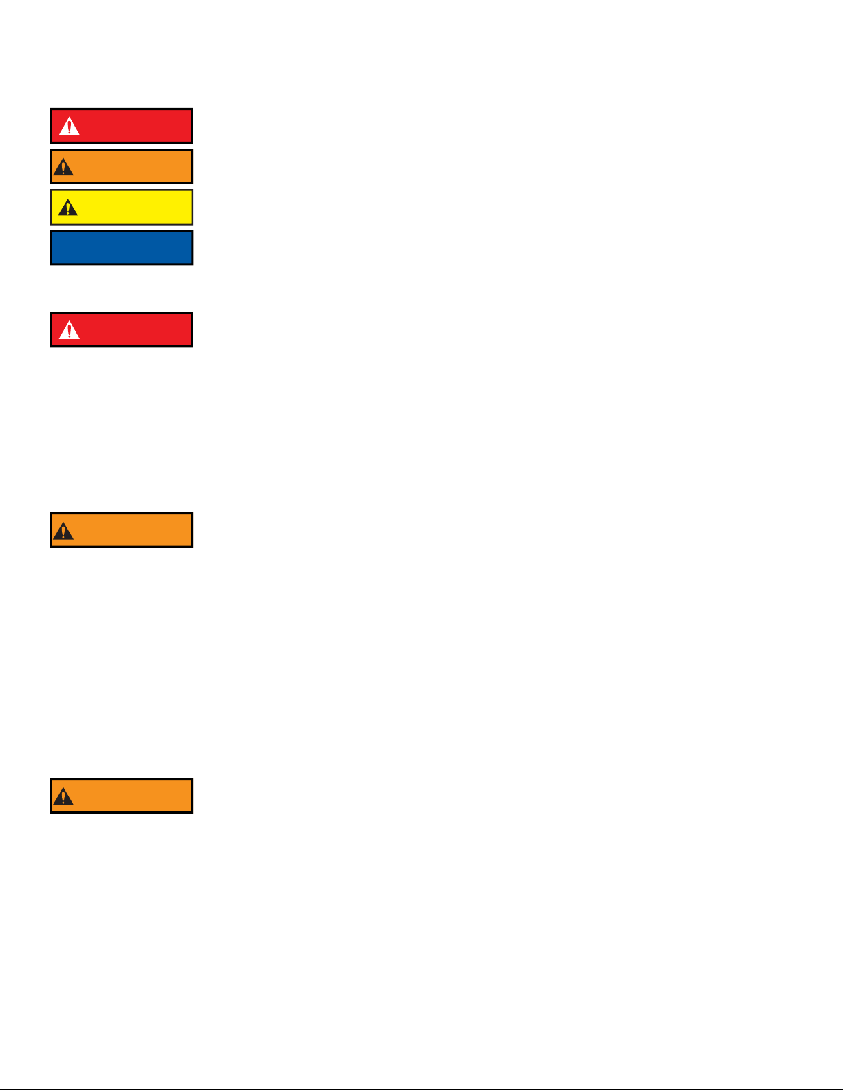
CAUTION Lifting or moving rescue tools and power units can result in falling or spine injury. Rescue tools and
power units are heavy. Risk of injury increases in unfavorable conditions such as poor lighting,
inclines, loose, wet, or icy surfaces. Follow accepted safe lifting practices.
NOTICE
Use of hydraulic fluids other than AMKUS MV1 or MV0 (see Specifications for fluid for specific tool
lines) can result in equipment damage and loss of function. Some examples include:
• Phosphate ester hydraulic fluids and blends are incompatible with Buna-N seal and hose
materials used in AMKUS Rescue Systems
• Mixing glycol with mineral oils can result in gelling and plugging of pump inlet screens
• Using fluids with wrong viscosity or wear properties. Always use AMKUS MV1 or MV0 as
specified for your tools.

©Copyright AMKUS Rescue Systems 2020-2021 6 LAI-004 July 20, 2021 Rev01
3.0 GENERAL DESCRIPTION
AMKUS manufactures a complete line of ION battery powered electro-hydraulic rescue tools. These rescue tools continue the AMKUS
tradition of superior craftsmanship and quality. AMKUS backs these tools with a standard warranty published on the AMKUS website.
The AMKUS ION tool's self-contained hydraulic system provides the motive forces needed to operate the tool. The brushless direct
current (DC) motor operates from energy stored in a 60 Volt battery. The DC motor drives a high pressure pump. Hydraulic fluid from the
pump passes through a user operated control valve and moves the piston as directed by the user. Moving the piston actuates the arms
or blades of the rescue tool.
3.1 VARIOUS MODELS AND TERMS
Battery
Lighted
Handle
Guard
Cutter Blades
Grip Control Valve
Actuator
Figure 3.1A
IC700 Cutter
Spreader
Arms
Removable
Tips
Lighted
Handle
Figure 3.1B
IS281 Spreader
Figure 3.1C
ITR500 Ram
Rotating
Grip Head
Telescoping
Piston
ON/OFF
Button
Rotating
Grip Head

©Copyright AMKUS Rescue Systems 2020-2021 7 LAI-004 July 20, 2021 Rev01
3.2 SAFETY MARKINGS
Figure 3.2
Product Information
Safety Label
Model #
Serial # (also engraved on tool)
Date of Manufacture
Fluid Type
Cutter, Spreader Telescoping Ram

©Copyright AMKUS Rescue Systems 2020-2021 8 LAI-004 July 20, 2021 Rev01
4.0 SPECIFICATIONS
4.1 GENERAL SPECIFICATIONS
Table 4.1
The 20V/60V MAX Battery pack changes voltage when you change tools, powering a line of powerful 60V MAX tools, 120V MAX tools,
and backwards compatible to existing 20V MAX tools and chargers. The battery pack is smart enough to know when to provide runtime
for 20V MAX tools and power in the new 60V MAX and 120V MAX tools.
Also compatible with:
DEWALT DCB1800B 1800 Watt Portable Power Station and Simultaneous Battery Charger - AMKUS ICHRG120-4
BATTERY SPECIFICATIONS
20V/60V MAX* FLEXVOLT 6.0 Ah BATTERY
Model: DeWALT DCB606
AMKUS Part # IBATTFV-6
Dimensions: Length x Width x Height inches (mm) 4.9 x 3.3 x 3.6 (124 x 84 x 91)
Weight LB (kg) 2.25 (1.0)
20V/60V MAX* FLEXVOLT 9.0 Ah BATTERY
Model: DeWALT DCB609
AMKUS Part # IBATTFV-9
Dimensions: Length x Width x Height inches (mm) 5.4 x 3.8 x 3.6 (137 x 97 x 91)
Weight LB (kg) 3.2 (1.45)
20V/60V MAX* FLEXVOLT 12.0 Ah BATTERY
Model: DeWALT DCB612
AMKUS Part # IBATTFV-12
Dimensions: Length x Width x Height inches (mm) 5.4 x 3.8 x 3.6 (137 x 97 x 91)
Weight LB (kg) 3.2 (1.45)
CHARGER SPECIFICATIONS Part#: ICHRG120
Model: DeWALT 20VMAX* Fan Cooled Fast Charger DCB118
Input Power [Volts AC] 120
Output [Volts DC] 20
Charge Current [A] 8
Dimensions: Length x Width x Height inches (mm) 7.6 x 4.7 x 3.3 (193 x 120 x 84)
Charge Time (minutes) 60
OPERATING LIMITS
Operating Temperature Range: Degrees F (C) -25 TO 140 (-32 TO 60)
ELECTRIC DRIVE SPECIFICATIONS
Motor Type Brushless
Input Voltage [Volts DC] 60
Rated Input Current: Amps 27
HYDRAULIC SPECIFICATIONS
Fluid Type: AMKUS MV1 Hydraulic Fluid (Part#) KF0001
Maximum Operating Pressure PSI (bar) 10,500 (724)

©Copyright AMKUS Rescue Systems 2020-2021 9 LAI-004 July 20, 2021 Rev01
4.2 CUTTER SPECIFICATIONS
Table 4.2
4.3 SPREADER SPECIFICATIONS
Table 4.3
4.4 TELESCOPING RAM SPECIFICATIONS
5.0 SAFETY CONSIDERATIONS
5.1 PROTECTIVE CLOTHING
5.2 TRAINING
Part#: IC700
MECHANICAL SPECIFICATIONS
Dimensions: Length x Width x Height Inches (mm) 32.9 x 8.7 x 11.6 (856 x 221 x 294)
Weight (excluding battery) lb (kg) 54.3 (24.6)
Weight (ready to use) lb (kg) 56.6 (25.6)
Cutter Opening Inches (mm) 5.8 (147)
Cutter Rating NFPA 1936 A7/B8/C7/D9/E9/F4
Part#: IS281
MECHANICAL SPECIFICATIONS
Dimensions: Length x Width x Height Inches (mm) 35.9 x 11.1 x 11.6 (912 x 282 x 294)
Weight (excluding battery) lb (kg) 53.9 (24.4)
Weight (ready to use) lb (kg) 56.3 (25.5)
Max Spreading Distance Inches (mm) 28.2 (716)
Max Spreader Opening (w/optional ERT tips) Inches (mm) 35.4 (899)
Highest Spreading Force (HSF) lb (kN) 16.430 (73.1)
Lowest Spreading Force (LSF) lb (kN) 11,850 (52.7)
Max Spreading Force lb (kN) 23,850 (106.1)
Highest Pulling Force (HPF) lb (kN) 12,860 (57.2)
Lowest Pulling Force (LPF) lb (kN) 9,200 (40.9)
Part#: ITR500
MECHANICAL SPECIFICATIONS
Dimensions: Length (Retracted) x Width x Height Inches (mm) 21.9 x 11.5 x 10.9 (556 x 292 x 277)
Dimensions: Length (Extended) x Width x Height Inches (mm) 50.5 x 11.5 x 10.9 (1283 x 292 x 277)
Weight (excluding battery) lb (kg) 54.30 (24.63)
Weight (ready to use) lb (kg) 56.55 (25.65)
Stroke: Piston 1 Inches (mm) 15 (381)
Stroke: Piston 2 Inches (mm) 13.55 (344)
Stroke: Overall Inches (mm) 25.55 (649)
Highest Spreading Force (HSF)- Piston 1 lbs (kN) 46,500 (206.8)
Lowest Spreading Force (LSF)- Piston 2 lbs (kN) 21,750 (96.7)
WARNING
Tool operators bear responsibility for ensuring use of appropriate protective clothing and
equipment. The chosen protective clothing and equipment must provide protection from potential
hazards users may encounter while operating AMKUS rescue tools. Requirements for protective
clothing and equipment are determined by the Authority Having Jurisdiction (AHJ).
WARNING
AMKUS tools facilitate the extrication of entrapment victims. Only trained emergency services
personnel should attempt victim extrication. All personnel using Amkus rescue tools are assumed
to have completed a training course covering safe extrication of entrapment victims. The training
must be acknowledged as educationally sound by the local Authority Having Jurisdiction (AHJ)
over such training.

©Copyright AMKUS Rescue Systems 2020-2021 10 LAI-004 July 20, 2021 Rev01
5.3 OPERATING CONSIDERATIONS
To avoid rescue tool overheating:
• Keep motor cooling vent holes unobstructed.
• Remove the battery prior to cleaning, servicing, or inspecting the tool.
• After use, clean off any accumulated oil, grease, dirt, or corrosive
substances with a damp cloth and soapy water.
6.0 SET-UP PROCEDURE
Normally, AMKUS equipment is prepared and serviced by your dealer prior to delivery. If, however, you have decided to place the
equipment into service yourself, remove equipment from the packing cartons and carefully inspect for damage. Damage that occurs
during shipment should be reported immediately to the carrier.
6.1 CHARGE THE BATTERY
6.2 INSTALL THE BATTERY
A quick push slides the battery into the tool. Slide the battery onto the tool until the latch clicks.
Figure 6.2
NOTICE
AMKUS tools are intended for intermittent use. Allow sufficiently long pauses for the rescue tool to
cool. If the tool’s exterior becomes too hot to touch, the temperature is likely above 120°F (49°C). An
overheated rescue tool operates less effectively. When hydraulic oil temperature reaches 158°F
(70°C), the tool’s efficiency drops significantly, and the tool should be stopped to cool down.
NOTICE
Operating the rescue tool continuously against an end stop may cause overheating resulting in an
inoperable tool. Permanent damage to the tool may occur. When an end stop is reached, release the
control handle to return the control to the neutral position.
NOTICE
Store electric tools in a dry place.
WARNING
Read and understand the battery and charger manufacturer’s documentation before using the
battery and charger.
WARNING
An accidental start-up may cause injury. Always make the tool safe by turning the tool off, removing
the battery, and removing hands from the controls when making adjustments or removing/installing
attachments or accessories.
Figure 5.3
Cooling Vent Holes

©Copyright AMKUS Rescue Systems 2020-2021 11 LAI-004 July 20, 2021 Rev01
6.3 POWER BUTTON ON/OFF
To Power ON - Press and release the silver power button to activate
the rescue tool. The power is on when the status LED indicator light
is on.
To Power OFF - Press, hold for 1 second, and release the power
button to shut off the rescue tool. The power is off when the status
LED indicator light is off.
The rescue tool will power off automatically after 20 minutes of
inactivity.
6.4 ROTATING HANDLE
ION Cutter and Combi Tools come equipped with a 360° swiveling handle that has variable tension.
Figure 6.4
6.4.1 HANDLE LIGHTS
AMKUS dual handle lights operate in one of two modes, an on/off mode (standard), or an optional mode with three intensity levels.
To operate the lights in the on/off mode, press the power button to turn the lights on. Press the button again to turn off.
To operate the lights in the three intensity level mode, press the power button to turn the lights on. Press the button to scroll through the
three intensity levels and then off.
To change between operating modes:
1. Press the button once to turn on the lights.
2. Press and hold the button until the lights flash.
3. The lights now operate in the alternate mode.
Power
Button
Status
LED
RELEASE
LOCK
TENSION
SCREW
To increase rotating handle tension,
tighten the tension screw shown above.
Flip the red latch up on the tool’s cuff to rotate the rescue tool.
Flip the latch down to lock the handle position.

©Copyright AMKUS Rescue Systems 2020-2021 12 LAI-004 July 20, 2021 Rev01
6.5 CONTROL VALVE ACTUATOR
The control valve actuator has three positions, OPEN (cutter, spreader) or EXTEND (ram), OFF, and CLOSE (cutter, spreader) or
RETRACT (ram). The control valve actuator includes a deadman safety feature which returns the control valve actuator to the OFF
position (neutral) when released. When the control valve is in the OFF position, the tool movement stops, and holds position and load.
The control valve actuator controls the motor and hydraulic pump. Electronics within the tool prevent electrical overload during
operation.
Verify operation of control valve actuator by checking to see it returns automatically to the neutral position when released.
7.0 OPERATION
7.1 BATTERY CHARGE STATUS
Check the battery charge status using the indicator lights on the battery by pushing the status button on the battery.
Figure 7.1
7.2 WHEN TO CHANGE THE BATTERY
ION tools keep power ON until turned off, or after 20 minutes of inactivity. The battery management system maintains power until the
battery is drained. Push the status button on the battery to check the battery status. The indicator light bars display the battery’s charge
status.
Change the battery if the battery no longer continuously operates the tool, there is one bar left on the battery charge indicator, or the
Status LED indicates “red” for low battery.
7.3 STORAGE RECOMMENDATIONS
1. The best storage place is cool and dry, away from direct sunlight and excess heat or cold.
2. For long storage, it is recommended to store a fully charged battery pack in a cool dry place out of the tool and charger for optimal
results.
3. If the tool is exposed to water, remove the battery. Allow the battery and tool to dry before storage or use.
7.4 STATUS LED
During tool operation, the brightness of the LED will adjust to indicate to the user the amount of power the tool is currently using to
operate. The brighter the LED the more power being applied to cutting or spreading. The LED is also used to communicate status of
important tool conditions to the operator. Error codes will not prevent the tool from operating. The codes are intended to alert the
operator of a potentially harmful condition.
LED COLOR STATUS MESSAGE
Green Battery Good
Red Battery Low
Yellow Tool in Error
• Temperature is over 113°F (45°C)
• Temperature is under 3°F (-16°C)
• Actuator ON, motor not running
• Actuator NOT ON, motor running
Flashing Red Battery Fault

©Copyright AMKUS Rescue Systems 2020-2021 13 LAI-004 July 20, 2021 Rev01
7.5 CUTTING
Rotation of the control valve actuator runs the electric motor and pump. Rotating the control valve actuator regulates the hydraulic flow
rate and power delivered to the tool. Turning the control valve actuator to the end stops provides maximum hydraulic flow rate and
power.
Figure 7.5
To perform a cutting operation, first, open the cutter blades. Place the blades around the object being cut. Close the blades to cut the
object. Obtain the maximum cutting forces nearest the pivot point. Start the cut with the blades as fully engaged as possible. Make the
cut. Open the blades and remove the tool when finished.
WARNING
When
When operating the cutter, take care to be positioned to the side of the cutter. As the cutter blades
meet resistance, the rescue tool may rotate or drift. If tool rotation places the user, operator, or
others in jeopardy, immediately release the control valve actuator. The deadman safety feature of
the control valve actuator should immediately return the control valve actuator to the center
(neutral) position stopping blade movement. Reposition the cutter as needed for optimal cutting
performance.
WARNING
Blades can break if positioned incorrectly, causing hazardous projectiles and an inoperable tool. If
blades start to flex sideways (tool rolls as space between blades increases), stop immediately and
reconsider cutting strategies.
CAUTION The blades on AMKUS cutters effectively cut steering columns, brake pedals, door mechanisms,
and other vehicle items as necessary for extrication. However, using AMKUS cutters as a piercing
tool for heavy metal is not recommended. Therefore, when cutting, take care to insure the blade tips
move through a clear path of travel. The blade tips can pierce automotive sheet metal body panels.
Avoid obstacles like the heavy metal backing plates hidden behind seat belt mounts, door hinges,
and latching mechanisms or locks.
NOTICE
Cutting hardened metals can potentially dent or deform the blade’s cutting edge. Blades may break
at these weak spots on subsequent cuts, especially if cutting near the tips. Avoid cutting hardened
solids of unknown strength such as:
• Padlock shackles
• Tie rods
• Leaf springs
• Spindles
• Hardened bolts
• Tool steel
• Heat treated chain
Blade damage or breakage that results from cutting hardened metals or solids is not covered by the
AMKUS Rescue Systems warranty.
The blades are intended and designed to cut hardened auto bodies and components without
damage.
We recommend an Authorized AMKUS Rescue Systems Dealer inspect, evaluate, and replace
dented or damaged blades as necessary.

©Copyright AMKUS Rescue Systems 2020-2021 14 LAI-004 July 20, 2021 Rev01
Figure 7.5
CORRECT BLADE POSITION INCORRECT BLADE POSITION
BLADE TIPS STAY TOGETHER BLADES FLEX FORCING TIPS APART

©Copyright AMKUS Rescue Systems 2020-2021 15 LAI-004 July 20, 2021 Rev01
7.6 SPREADING / SQUEEZING / LIFTING
Rotating the control valve actuator regulates the hydraulic flow rate and power delivered to the tool. Turning the control valve actuator to
the end stops provides maximum hydraulic flow rate and power.
Figure 7.6A
Figure 7.6B
For exchanging spreader tips, See Section 8.1 on page 17.
WARNING
When
When operating the spreader, the tool may rotate as it meets resistance. If tool rotation places the
user, operator, or others in jeopardy, immediately release the control valve actuator. Stop and
modify the extrication procedure. The deadman safety feature returns the control valve actuator to
the center (neutral) position stopping arm movement. Seek another purchase point to proceed with
the extrication.
WARNING
When
Spreading, squeezing, pulling, and lifting operations can cause loads to become unstable. Unstable
loads can cause injury or death. To avoid load instability:
• Position the spreader tips to maintain maximum contact with the surfaces to be spread, gripped
or lifted.
• Always stabilize the object being lifted.
TIPS MAY SLIP
INCREASE GAP AND
REPOSITION TIPS
CORRECT
STARTING POSITION
INCORRECT
STARTING POSITION

©Copyright AMKUS Rescue Systems 2020-2021 16 LAI-004 July 20, 2021 Rev01
7.7 TELESCOPING RAM OPERATION
The telescoping ram has two stages that extend out in sequence. The first stage has a higher force than the second stage due to its
larger diameter.
Figure 7.7A
Table 7.7B
WARNING
Crushing from falling or rolling loads may result in injury or death. To reduce risk, observe the
following:
• Identify the crush zone. These are areas under the load and around the load with risk of
crushing from a falling or rolling load.
• Position the ram base securely against a support surface. Excess space may be taken up using
cribbing.
• Extend the lifting head to the object being displaced.
• Ensure nearby people are clear of the crush zone before lifting or retracting.
• Displace the object only as far as needed.
• Stop to stabilize the load in increments as the load is lifted or lowered.
NOTICE
The telescoping ram is used in pushing and lifting objects with pistons extending. The load is held
when the control valve actuator is in OFF (neutral) position. The ram is NOT to be used for pulling
tension loads with pistons retracting.
CORRECT STARTING POSITION INCORRECT STARTING POSITION
Too much space
Space filled
with cribbing
To
o much s
pa
ce

©Copyright AMKUS Rescue Systems 2020-2021 17 LAI-004 July 20, 2021 Rev01
8.0 ACCESSORIES
8.1 EXTENDED REACH SPREADER TIPS (ERT)
The ION spreaders use removable tips. To remove the spreader tip, use a thumb and finger to depress the spring loaded tip pins, and
remove the tips. To re-install the spreader tip, slide the tip back into place. Be sure that both pins return fully to their original positions.
The reach and versatility of the spreader can be increased by using the Extended Reach Tips (ERT). ERT tips are interchangeable with
the standard tips.
Figure 8.1
8.2 CHAIN USE
Chain kits are available for spreaders.
Setup and operation of the chain kit:
• Secure the chains around the load, latching the grab hooks
fully across the chain. Remove any slack. (Tip hooks must not
be inserted into the holes in the chain links.)
• Remove slack in the chain using quick adjust links (spreader),
or grab hooks (combi)
• Tension the chain slightly and check to see that the
connections are stable and safe
• Activate the control valve actuator to close the arms and draw
the load
Chain Rating: 3/8” grade 70 Transport chain, working load limit
6600 lbs (29.94 kN)
Figure 8.2B
WARNING
Transport chain is NOT rated for overhead lifting. Injury or death may occur from improper chain
use. Observe chain safety guidelines established by the Authority Having Jurisdiction.
GATOR TIP ERT
COMBINATION
GATOR TIP AND ERT
COMBINATION
OFFSET ERT
PUSH TO RELEASE
Figure 8.2A
LOCK
RELEASE

©Copyright AMKUS Rescue Systems 2020-2021 18 LAI-004 July 20, 2021 Rev01
9.0 SAFETY GUARDS
Tools with moving blades have a guard over the moving parts. The guard is secured with screws which can be removed to clear debris
during maintenance. Reinstall guards after maintenance.
Figure 9.0
10.0 INSPECTION AND MAINTENANCE
PERIODIC MAINTENANCE SCHEDULE
Table 10.0
10.1 ROUTINE MAINTENANCE
10.1.1 CHECK THE BLADES
The use of damaged blades decreases the cutting efficiency of the tool and can overheat the motor.
Replace the blades when they become worn, cracked, or gouged. (Consult AMKUS Rescue Systems)
Check the torque on the cutter and combination tool pivot bolt monthly. Proper pivot bolt torque is 140 ft-lb (190 N-m).
10.1.2 HYDRAULIC MAINTENANCE
The pressure relief valve is not user adjustable. Attempting to adjust the PRV may cause damage and make the PRV inoperable.
10.1.3 MOTOR MAINTENANCE
Keep the motor cooling vents clean and unobstructed.
Frequency
(Hours of Use) Operation Method Responsible
Party
AFTER EVERY
USE
CHECK BLADES, TIPS, ARMS, AND RAM PISTONS FOR WEAR or
DAMAGE
Visual
Operator
EVERY 8 HOURS
CHECK THE TOOL FOR DAMAGE, VERIFY OPERATING
CONTROLS BEFORE AND AFTER EACH USE
Visual
ENSURE ALL NUTS AND BOLTS ARE SECURE Visual and
Hand Tools
WARNING
When
Perform all maintenance, inspection, and cleaning operations after the battery is removed and the
tool is cooled down to avoid injury or damage to the tool (see the Responsible Party in the
maintenance schedule).
Clean and inspect the tool before starting any maintenance work.
Annual tool maintenance shall be completed regardless of how many hours the tool has been used
since its last maintenance.
Figure 10.1.3
Cooling Vent Holes

©Copyright AMKUS Rescue Systems 2020-2021 19 LAI-004 July 20, 2021 Rev01
10.1.4 LUBRICATION
Cutter blades, combi blades, spreader arms, links, and pins are lubricated with white lithium grease. Annual re-lubrication per AMKUS
Service Procedures is recommended for average service conditions. More frequent lubrication may be required for severe or frequent
usage conditions.
10.1.5 HANDLE LIGHT BATTERY REPLACEMENT
To replace the batteries:
1. Remove the lid screws with a 3 mm hex key.
2. Remove and replace the 2 AA batteries in the battery holder.
3. Use the hex key to tighten the lid screws back into position.
11.0 TROUBLESHOOTING
11.1 GENERAL
Malfunctions can be divided into three sections:
1. Malfunction of the electric motor
2. Malfunction of the hydraulic system
3. Malfunctions related to other rescue tool components or systems
Remedies marked by the letter M require the intervention of the Maintenance Technician.
Remedies marked with the letter O can be performed by the Operator.
11.2 TROUBLESHOOTING THE MOTOR
Table 11.2
11.3 TROUBLESHOOTING THE HYDRAULICS
Table 11.3
NOTICE
Immediately remove malfunctioning or damaged tools from service. Consult your dealer or AMKUS
Rescue Systems.
ALL SERVICE MUST BE PERFORMED BY QUALIFIED SERVICE TECNICIANS IN OBSERVANCE OF
SAFETY REGULATIONS.
PROBLEM POSSIBLE REASON POSSIBLE REMEDY PERFORMED BY
MOTOR DOES
NOT START
Battery defective Replace battery O
Tool not turned on Press and release the
power button O
Battery not charged Charge battery O
PROBLEM POSSIBLE REASON POSSIBLE REMEDY PERFORMED BY
ELECTRONIC
MOTOR
OVERHEATED
Battery overheated Allow battery to cool O
Cooling vents obstructed Clean cooling vents O
PROBLEM POSSIBLE REASON POSSIBLE REMEDY PERFORMED BY
STROKE DOES
NOT BEGIN Control valve actuator damaged Replace control valve M
MOTOR DOES
NOT STOP
Battery shorted Replace battery O
Control valve actuator stuck Blow out control valve with
air/Consult Authorized
AMKUS Service Tech
M,O
DISCONTINUOUS
STROKE Max. pressure valve fault Consult AMKUS Service
Department M,O
Figure 10.1.5
REMOVE
SCREWS

©Copyright AMKUS Rescue Systems 2020-2021 20 LAI-004 July 20, 2021 Rev01
AMKUS RESCUE SYSTEMS
AMKUS.com
4201 Montdale Drive, Valparaiso, IN 46383-4098 USA
800-592-6587 · 219-548-5000
12.0 PARTS, SERVICE, AND TECHNICAL INFORMATION
Parts, service, and technical information may be obtained from your local AMKUS dealer, or at amkus.com
13.0 DECOMMISSIONING
When decommissioning any AMKUS Rescue Systems Tool or power supply, follow local regulations. For proper disposal information,
contact your local AMKUS Rescue Systems dealer.
14.0 INSPECTION, CLEANING, DECONTAMINATION, AND STORAGE
1. Always store the tool securely in a clean, cool, dry space.
2. Relieve the pressure on the tools after use by backing off the end stop.
3. Remove the battery from the tool.
4. Charge the battery.
BEFORE BEING PLACED BACK IN SERVICE, the rescue tool must be inspected to this list:
1. Check to see that all rescue tool markings are legible.
Contact your local dealer or AMKUS Rescue Systems for replacement labels.
2. Wipe the tool clean.
3. If the rescue tool becomes contaminated, determine the nature of the contamination. Follow the decontamination guidelines
provided by the Authority Having Jurisdiction. Technical advice may be requested from AMKUS Rescue Systems.
4. Inspect the tool, controls, and battery after each use for damage, leakage, and excessive wear.
5. If rescue tool damage or excessive wear is noticed, remove the rescue tool from service immediately.
Contact your local dealer or AMKUS Rescue Systems for service.
6. Install battery and verify tool operation.
WARNING
Any equipment failing any part of this checklist is unsafe for use and must have the problem
corrected before use or being placed back in service. Operating equipment that has failed the
checklist is a misuse of this equipment. Contact your local AMKUS dealer or AMKUS Rescue
Systems.
This manual suits for next models
2
Table of contents
Other Amkus Power Tools manuals