Amphenol LINC-1RUK-48LCA1-100F User manual

Installation Guide

2
Amphenol Network Solutions
All rights reserved. 04.25.23 152738 A0
1-509-926-6000 —amphenol-ns.com
Installation Guide, Part Number 152738
Copyright 2023, Amphenol Network Solutions. All Rights Reserved
Network Solutions is a registered trademark of Amphenol Network Solutions.
22425 East Appleway Ave. #11
Liberty Lake, WA 99019
Amphenol Network Solutions assumes no liability from the application or use of these products. Neither does Amphenol
Network Solutions convey any license under its patent rights nor the patent rights of others. This document and the
products described herein are subject to change without notice.
Connecting the future for more than 40 years
Amphenol Network Solutions challenges the status quo and looks beyond what is possible in network connectivity and
power management.
Founded in 1982, Amphenol Network Solutions, formerly Telect, is driven by the principles of innovation and customer
service. Headquartered in Liberty Lake, WA, the privately held company supports a global network of customers with a
comprehensive product portfolio and a values-driven corporate culture.
Our products and solutions are found across communications service-provider networks, data centers and utility networks
around the globe.
At Amphenol Network Solutions, we pride ourselves on our ability to respond to customer challenges, building a
reputation among communications service providers for delivering solutions uniquely tailored to their needs.
•Custom-configured solutions
•Products integrate seamlessly into existing infrastructure
•Exceptional customer service
•Hassle-free warranty
Technical Support
Email: support@amphenol-ns.com
Phone: 509-926-6000

3
Amphenol Network Solutions
All rights reserved. 04.25.23 152738 A0
1-509-926-6000 —amphenol-ns.com
Contents
1Introduction .....................................................................................................................................................................5
1.1 About this Guide .......................................................................................................................................................6
2Specifications..................................................................................................................................................................7
2.1 Chassis Dimensions .................................................................................................................................................7
2.2 Panel Capacity and Weight ......................................................................................................................................8
3Installation Considerations..............................................................................................................................................8
3.1 Inspection .................................................................................................................................................................8
3.2 Unpacking.................................................................................................................................................................9
3.3 Location and Space..................................................................................................................................................9
3.4 Tools and Equipment................................................................................................................................................9
4LiNC Panel Rack Mounting...........................................................................................................................................10
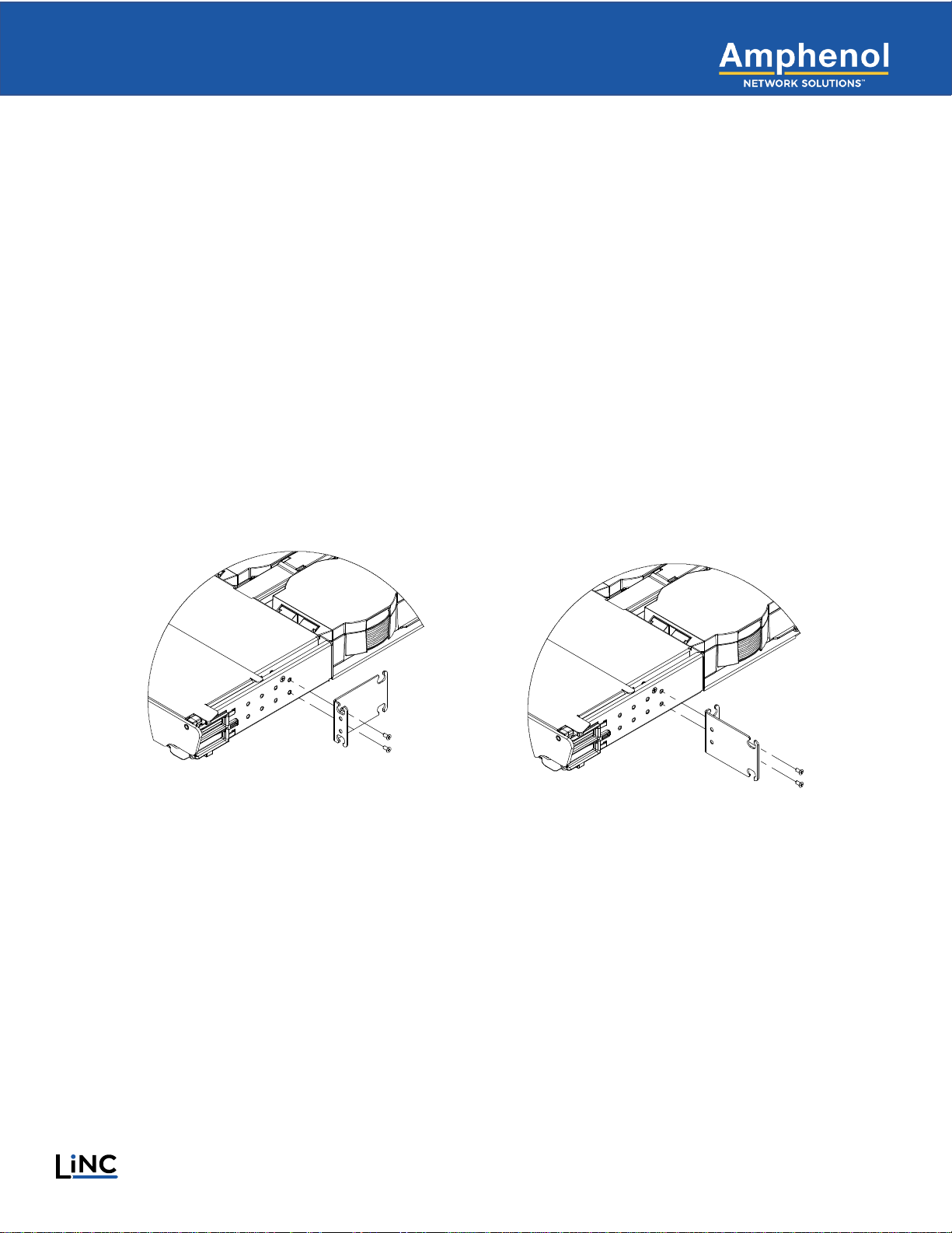
4.1 Adjusting Mounting Brackets on a LiNC Chassis...................................................................................................10
4.2 Preparing for Installation.........................................................................................................................................12
4.3 Installing the LiNC Chassis on a Rack ...................................................................................................................12
5LiNC Panel Installation and Connections......................................................................................................................13
5.1 Panel Overview.......................................................................................................................................................13
5.2 Connect MPO Trunk Cable.....................................................................................................................................13
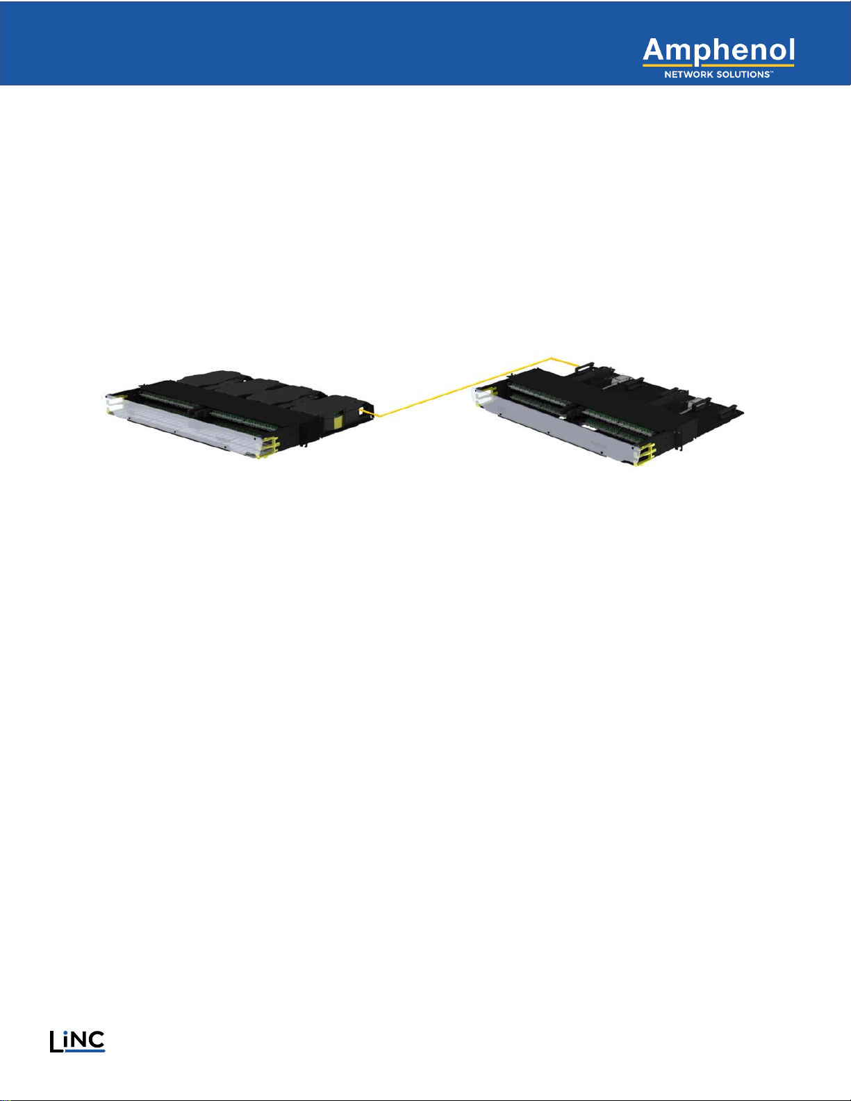
5.3 Connect MPO Trunk Cable to Remote Panel.........................................................................................................14
5.4 Utilizing an Auxiliary Cable Spool for Longer MPO Connections...........................................................................16
5.5 Connect MPO Trunk Cable to Breakout Module....................................................................................................17
5.6 Connect Fiber Jumpers on Front of Panel..............................................................................................................19
5.7 Designation.............................................................................................................................................................19
6Service ..........................................................................................................................................................................20
6.1 Owner Maintenance................................................................................................................................................20
6.1.1 High Insertion Loss and the Importance of Cleaning Connectors and Adapters..........................................20
6.1.2 Removing LiNC Modules for Service............................................................................................................20
7Customer Service and Ordering Information ................................................................................................................21
7.1 In-Warranty Service................................................................................................................................................21
7.2 Out-of-Warranty Service.........................................................................................................................................21
7.3 Repackage for Shipment........................................................................................................................................21
7.4 Ordering Accessories .............................................................................................................................................22
7.4.1 List of Accessories ........................................................................................................................................22

4
Amphenol Network Solutions
All rights reserved. 04.25.23 152738 A0
1-509-926-6000 —amphenol-ns.com
Table of Figures
Figure 1-1 LiNC Spool Panel (left) and Remote Panel (right).................................................................................................5
Figure 2-1 Chassis Dimensions..............................................................................................................................................7
Figure 4-1 19-Inch (left) and 23-Inch (right) Mounting Options.............................................................................................10
Figure 4-2 Mounting Bracket Location Options (top view)....................................................................................................11
Figure 4-3 Zip Tie Used to Secure Module (right, with arrow)..............................................................................................12
Figure 4-4 LiNC Chassis Rack Mounting..............................................................................................................................12
Figure 4-5 LiNC Spool Panel with Front Door Open (left) and Top Door Open (right).........................................................13
Figure 5-1 LiNC Spool Panel with Spool Assembly Partially Removed for Easier Access ..................................................13
Figure 5-2 LiNC Spool Assembly with Doors Closed (left) and Open (right)........................................................................14
Figure 5-3 Close-Up of Release Tab on Spool Assembly, Locked (left) and Unlocked (right).............................................14
Figure 5-4 MPO Trunk Cable Connection on Remote Panel................................................................................................15
Figure 5-5 Auxiliary Spool (left); Inner Spool Installs in Spool Assembly (right)...................................................................16
Figure 5-6 MPO Trunk Cable to Connect to Breakout Module.............................................................................................17
Figure 5-7 Cable Routing and MPO Connection to Breakout Module..................................................................................17
Figure 5-8 Secured Spool Assembly with MPO Trunk Cable Exiting via Cable Management Features..............................18
Figure 5-9 Fiber Optic Jumpers Connected and Routed on Front of LiNC Panel ................................................................19
Figure 5-10 Pre-Installed Designation Labels, Front (left) and Rear (right)..........................................................................19

5
Amphenol Network Solutions
All rights reserved. 04.25.23 152738 A0
1-509-926-6000 —amphenol-ns.com
1 Introduction
•The LiNC system provides a high-density solution that is simple to deploy
•A complete LiNC system includes one 1 RU spool panel and one 1 RU remote panel
•Each chassis houses four modules for a total of up to 96 LC or 48 SC connectors
•This guide explains how to:
oInstall the LiNC chassis in a rack
oComplete all required MPO trunk cable connections
oRoute and secure the fiber optic cable within the chassis
Figure 1-1 LiNC Spool Panel (left) and Remote Panel (right)

6
Amphenol Network Solutions
All rights reserved. 04.25.23 152738 A0
1-509-926-6000 —amphenol-ns.com
1.1 About this Guide
This manual provides a comprehensive overview and installation guidelines for the LiNC chassis. While
care has been taken to define all necessary information, complete details may not be covered. If you have any
questions, contact Amphenol Network Solutions Technical Support at support@amphenol-ns.com or call
1.509.926.6000.
Throughout this guide, relevant and crucial information is displayed in the form of Notes, Alerts, Cautions and
Warnings. These notifications are prominently displayed, and their importance is indicated as follows:
NOTE: General information the user should pay special attention to.
Alert! Important information and/or instructions the user should adhere to.
CAUTION! Indicates a hazardous situation, which if not avoided could result in minor or moderate injury.
WARNING: Indicates a potentially hazardous situation which if not avoided could result in death or
serious injury.
Amphenol Network Solutions assumes no liability from the application or use of these products. Neither does
Amphenol Network Solutions convey any license under its patent rights of others. This document and the products
described herein are subject to change without notice.

7
Amphenol Network Solutions
All rights reserved. 04.25.23 152738 A0
1-509-926-6000 —amphenol-ns.com
2 Specifications
2.1 Chassis Dimensions
Figure 2-1 Chassis Dimensions

8
Amphenol Network Solutions
All rights reserved. 04.25.23 152738 A0
1-509-926-6000 —amphenol-ns.com
2.2 Panel Capacity and Weight
Sample systems listed below—each includes spool panel, remote panel, and spooled MPO trunk cable.
Part Number
Description
Weight
LINC-1RUK-48LCA1-100F
48 LC/APC Capacity, 100-foot MPO cable
14.5 lbs. (6.6 kg)
LINC-1RUK-96LCA2-45F
96 LC/UPC Capacity, 45-foot MPO cable
14.8 lbs. (6.7 kg)
LINC-1RUK-96LCA2-100F
96 LC/UPC Capacity, 100-foot MPO cable
17.3 lbs. (7.8 kg)
3 Installation Considerations
WARNING! Fiber cables transmit invisible infrared light. To avoid eye damage or blindness, never look directly
into fibers or connectors.
CAUTION! These instructions presume you have verified that the Amphenol Network Solutions equipment being
installed is compatible with the rest of the system including power, ground, circuit protection, signal
characteristics, equipment from other vendors, and local codes or ordinances.
ALERT! This product must be installed and maintained only by qualified technicians.
ALERT! Install this system according to company requirements. It is recommended to install the system in a
Restricted Access Location (RAL) where access is limited through use of tool, lock and key, or other means
of security and be controlled by the authority responsible for the location.
ALERT! Prior to panel installation, ensure there is enough space in front and rear to access cabling.
ALERT! Only use components and crimping tools approved by agencies or certifying bodies recognized in
your country or region, such as Underwriter’s Laboratories (UL), TUV, etc.
ALERT! Do not stand on fiber or fiber cables.
3.1 Inspection
When you receive the equipment, carefully unpack contents and compare it to the packaging list. Please report any
defective or missing parts to Amphenol Network Solutions Quality at quality@amphenol-ns.com or call 1.509.926.6000.
Keep all documentation that comes with your shipment.
Please read and understand all instructions before starting installation. If you have any questions, contact Amphenol
Network Solutions Technical Support at support@amphenol-ns.com or call 1.509.926.6000.
Exercise care when unpacking and setting the equipment in place. Amphenol Network Solutions is not liable for transit
damage. If the product is damaged, please report it to the carrier and contact Amphenol Network Solutions Quality.

9
Amphenol Network Solutions
All rights reserved. 04.25.23 152738 A0
1-509-926-6000 —amphenol-ns.com
3.2 Unpacking
Upon receipt of your order, carefully unpack contents and compare it with the packing list and the order placed. While
items described below are a comprehensive list that includes the LiNC chassis and brackets and doors, the contents
of your order may vary.
•LiNC Spool chassis
•LiNC Remote chassis
•Breakout modules –installed
•MPO Spool assembly –installed
•Mounting brackets –installed
•Designation labels –installed
•Top and front panel doors –installed
•Pull-tab MPO connector handles
•#12-24 Rack mounting screws
•Auxiliary MPO spools (not all configurations)
•Quick guide
3.3 Location and Space
The LiNC chassis requires space in the front and rear for access to patching and cabling. Leave as much side
clearance for tray and worker access as required by your application or local regulations. Plan the input/output and
cable feed of the chassis before installation.
The chassis comes equipped with 19" mounting brackets pre-installed.
3.4 Tools and Equipment
Installation requires a Philips head screwdriver. No other special tools are required to assemble the LiNC panel.

10
Amphenol Network Solutions
All rights reserved. 04.25.23 152738 A0
1-509-926-6000 —amphenol-ns.com
4 LiNC Panel Rack Mounting
Please read these instructions carefully before beginning installation. If you need assistance, call Amphenol Network
Solutions at 509-926-6000 or email us at support@amphenol-ns.com.
Inspect equipment after unpacking and compare it to the packing list.
Immediately report any shipping damage, defects or missing parts to Amphenol Network Solutions at 509-926-6000.
Keep all documentation that comes with your shipment.
Amphenol Network Solutions is not liable for shipping damage. If the product is damaged, notify the carrier and call
Amphenol Network Solutions at 509-926-6000 for further recourse.
NOTE: For service or warranty information, please visit www.amphenol-ns.com and click on the “Support” tab, email us at
support@amphenol-ns.com or phone us at 509-926-6000.
This section covers how to prepare and mount the LiNC chassis and pre-installed modules.
4.1 Adjusting Mounting Brackets on a LiNC Chassis
LiNC chassis includes two mounting brackets, one per side, to attach the LiNC chassis to a 19" or 23" EIA rack.
Brackets are pre-installed for 19" racks. For 23" racks, remove and reverse the mounting brackets.
Figure 4-1 19-Inch (left) and 23-Inch (right) Mounting Options

11
Amphenol Network Solutions
All rights reserved. 04.25.23 152738 A0
1-509-926-6000 —amphenol-ns.com
Mounting brackets arrive pre-installed on the chassis in the standard position, but if the position of the brackets needs to
be changed, a multi-hole pattern allows the chassis to be offset towards the front or rear in accordance with customer
requirements.
To change the position of the mounting bracket:
1. Remove mounting bracket using a Phillips screwdriver.
2. Align mounting bracket screw holes with the screw holes in the sidewall of the chassis.
Insert screws through outside holes of the bracket into the panel sidewall.
3. Using a Phillips screwdriver, tighten screws to secure the bracket to the panel.
4. Repeat Steps 1 –3 for the remaining bracket on the opposite side.
Figure 4-2 Mounting Bracket Location Options (top view)

12
Amphenol Network Solutions
All rights reserved. 04.25.23 152738 A0
1-509-926-6000 —amphenol-ns.com
4.2 Preparing for Installation
Remove all packing materials. Carefully cut and remove zip ties at rear of each spool assembly.
Figure 4-3 Zip Tie Used to Secure Module (right, with arrow)
4.3 Installing the LiNC Chassis on a Rack
Using a Phillips head screwdriver and the provided screws, install the chassis on the rack by aligning the mounting holes
in the bracket with the holes in the rack. Follow these steps:
1. Partially install screws corresponding with the lower mounting rack hole position for each side of the panel. Do not
tighten the screws completely.
2. Slide the mounting brackets downward into place behind the partially installed screws.
3. Secure the panel by tightening screws in both the top and bottom positions of each mounting bracket.
Figure 4-4 LiNC Chassis Rack Mounting

13
Amphenol Network Solutions
All rights reserved. 04.25.23 152738 A0
1-509-926-6000 —amphenol-ns.com
For easier access during the remaining installation steps, slide the top cover toward the rear of the panel and open the
clear front door.
Figure 4-5 LiNC Spool Panel with Front Door Open (left) and Top Door Open (right)
5 LiNC Panel Installation and Connections
5.1 Panel Overview
Each LiNC system includes a spool panel and a remote panel. Modules pre-installed in the spool panel feature spools
with 45 feet of 24-fiber or 100 feet of 12-fiber MPO trunk cable for cross-connection. The spool should be utilized for
excess trunk cable storage.
NOTE: Additional trunk cable lengths can be ordered and are shipped with auxiliary spools.
5.2 Connect MPO Trunk Cable
Starting at the rear of the panel, users can remove the spool assembly from the chassis for easier access. Spool
assemblies are secured in the chassis by magnets. Prior to making any connections, pull the spool assembly toward the
rear of the panel to release the magnetic connection. To replace the spool assembly, set it on the floor of the chassis and
slide it back toward the middle of the chassis until it secures in place, making sure to locate the base of the spool
assembly under the mushroom-shaped posts for security.
Figure 5-1 LiNC Spool Panel with Spool Assembly Partially Removed for Easier Access

14
Amphenol Network Solutions
All rights reserved. 04.25.23 152738 A0
1-509-926-6000 —amphenol-ns.com
Access the interior of the spool assembly by opening the protective front door downward and lifting the top cover.
Figure 5-2 LiNC Spool Assembly with Doors Closed (left) and Open (right)
OPTIONAL: If desired, clip the included pull-tab handles onto the MPO connector housing. This simplifies handling of the
MPO connector in the following steps.
5.3 Connect MPO Trunk Cable to Remote Panel
Slide the yellow locking tab to unlock the cable spool.
Figure 5-3 Close-Up of Release Tab on Spool Assembly, Locked (left) and Unlocked (right)

15
Amphenol Network Solutions
All rights reserved. 04.25.23 152738 A0
1-509-926-6000 —amphenol-ns.com
Using the end of the MPO trunk cable facing rearward (it is wound on the lower section of the cable spool), gently unspool
the cable to the desired length and connect to the remote panel.
Route fiber through cable management rings on the rear of the remote panel.
Figure 5-4 MPO Trunk Cable Connection on Remote Panel
If necessary, at the spool panel, wind the spool counter-clockwise to remove excess slack cable.
Slide the locking tab to lock the cable spool in place.

16
Amphenol Network Solutions
All rights reserved. 04.25.23 152738 A0
1-509-926-6000 —amphenol-ns.com
5.4 Utilizing an Auxiliary Cable Spool for Longer MPO Connections
MPO Trunk cable runs greater than 45 feet of 24-fiber cable or 100 feet of 12-fiber cable must utilize an auxiliary cable
spool. In these applications, all cable must be utilized from the auxiliary spool. The auxiliary spool is comprised of
recyclable materials and can be disposed of as such.
Connect one end of the MPO trunk cable to the appropriate connector at the rear of the remote panel.
Unspool the cable to desired length. After removing all cable from the auxiliary spool, remove the inner spool from the
auxiliary spool. Install the inner spool in a spool assembly. Install the spool assembly as described in section 5.2.
Figure 5-5 Auxiliary Spool (left); Inner Spool Installs in Spool Assembly (right)

17
Amphenol Network Solutions
All rights reserved. 04.25.23 152738 A0
1-509-926-6000 —amphenol-ns.com
5.5 Connect MPO Trunk Cable to Breakout Module
Uncoil the MPO trunk cable from the top of the spool. Route it around the bend radius protection features and out of the
spool assembly.
Figure 5-6 MPO Trunk Cable to Connect to Breakout Module
OPTIONAL: If desired, clip the included pull-tab handles onto the MPO connector housing. This simplifies handling of the
MPO connector in the following steps.
Connect the cable to the MPO connector at the rear of the breakout module, leaving a small amount of slack cable to
enable slight forward movement of the breakout module during jumper connection without impacting the MPO connection
on the rear of the module. Route the slack cable through the cable management on the spool assembly.
Figure 5-7 Cable Routing and MPO Connection to Breakout Module

18
Amphenol Network Solutions
All rights reserved. 04.25.23 152738 A0
1-509-926-6000 —amphenol-ns.com
Route the trunk cable through cable management features on the spool assembly.
Figure 5-8 Secured Spool Assembly with MPO Trunk Cable Exiting via Cable Management Features

19
Amphenol Network Solutions
All rights reserved. 04.25.23 152738 A0
1-509-926-6000 —amphenol-ns.com
5.6 Connect Fiber Jumpers on Front of Panel
LiNC Breakout modules feature four 24-port LC or 12-port SC patch platforms on the front of the panel for a total of 96
LC or 48 SC patch ports.
Using the handle located on the inboard edge of each module, pull the module forward slightly to the service position for
easier access. The magnetic connection will disengage.
Connect jumpers as desired using the patch ports on the front of the panel.
Push the module handle sideways toward the center of the panel and slide the module back into place until the magnetic
connection re-engages.
Route fiber through cable management features at the side of the panel. Use the top opening for jumpers connected to
the top row of patch ports, and the bottom opening for jumpers connected to the bottom row of patch ports. Fibers can be
routed fully or partially to the left or right side of the panel.
Figure 5-9 Fiber Optic Jumpers Connected and Routed on Front of LiNC Panel
5.7 Designation
Each LiNC panel features pre-installed designation labels for front and rear connections. Slide the labels out to a usable
position, then replace once circuit designation is complete.
Figure 5-10 Pre-Installed Designation Labels, Front (left) and Rear (right)

20
Amphenol Network Solutions
All rights reserved. 04.25.23 152738 A0
1-509-926-6000 —amphenol-ns.com
6 Service
6.1 Owner Maintenance
The Amphenol Network Solutions LiNC system does not require any preventative maintenance. If equipment is not
working properly, contact technical support and be advised of the following warning/caution/alert.
WARNING! To avoid eye damage or blindness, never look directly into fibers or connections.
CAUTION! Wear safety glasses while working with exposed fiber optic fiber. Do not touch eyes while working
with fiber optic fibers.
ALERT! This product must be installed and maintained by qualified technicians.
6.1.1 High Insertion Loss and the Importance of Cleaning Connectors and Adapters
The major causes for poor performance (high insertion loss) are:
• Attenuation due to too sharp or too many close radius bends in the fiber cable
• Loose connections
• Dirty connectors or adapters
If you experience insertion loss greater than 2.5 dB, check for sharp bends and loose connections. Clean all polished
ferrules on pigtails and both ends of the patch cord or jumper.
Though Amphenol Network Solutions includes dust caps with all adapters and connectors, it isn’t always possible to
ensure that fiber ferrules stay clean. If you need to clean connectors and adapters, Amphenol Network Solutions
recommends a commercially available system or solution. Special formulation for cleaning fiber ferrules allows the
commercial solvent to stay liquid long enough to dissolve impurities quickly and thoroughly, yet evaporate quickly after
wiping dry. Always allow the ferrules to air dry thoroughly before reconnecting. “Canned air” can be used to clean away
debris initially, but do not use an aerosol after cleaning polished surfaces. Most aerosols contain contaminants.
If a commercial solution is not available, a reagent-grade ethyl alcohol, nominally USP > 99%, can be used. These
generally are available at typical pharmacies.
6.1.2 Removing LiNC Modules for Service
To access LiNC connectors for service, follow these steps:
1. Disconnect the MPO trunk cable at the rear of the module.
2. From the front of the module, use the handle on the inside of the module to slide the module forward, releasing the
magnetic connection.
3. Depress the barb on the inside rear of the module. If the barb cannot be reached by hand, a simple tool such as a
standard screwdriver can be used, or an adjacent spool can be removed to gain hand access. The barb is in place to
prevent moving the module too far forward and damaging the MPO connector when the cable is connected.
4. After service, reverse these steps to return the module to standard position.
This manual suits for next models
2
Table of contents
Other Amphenol Network Hardware manuals
Popular Network Hardware manuals by other brands

ICP DAS USA
ICP DAS USA DB-24PR/24 quick start guide

Patton electronics
Patton electronics SMARTNODE 4900 quick start guide

Bosch
Bosch VIP-X1XF Installation and operating manual

Cradlepoint
Cradlepoint AER 2100 quick start guide

Panasonic
Panasonic K-NL408KT/G quick start guide

ZyXEL Communications
ZyXEL Communications NSA-2400 user guide