Amphenol Tempsonics Level Plus LLE User manual

Magnetostrictive Liquid Level Transmitters with Temposonics®Technology
Level Plus®– LLE
Operation Manual
Compact Level Measurement
Inherent Accuracy +/-0.5 mm
No Scheduled Maintenance or Recalibration
Optional Integral Temperature Measurement

Table of contents
1. Contact information.......................................................................................................................................... 3
2. Terms and definitions........................................................................................................................................ 4
3. Introduction ................................................................................................................................................... 5
3.1 Purpose and use of this manual ................................................................................................................................................................ 5
3.2 Used symbols and warnings ..................................................................................................................................................................... 5
4. Safety instructions ........................................................................................................................................... 5
4.1 Intended use.............................................................................................................................................................................................. 5
4.2 Foreseeable misuse................................................................................................................................................................................... 5
4.3 Installation, commissioning and operation................................................................................................................................................ 6
5. Product overview............................................................................................................................................. 7
5.1 Components.............................................................................................................................................................................................. 7
5.2 Accuracy.................................................................................................................................................................................................... 7
5.3 Warranty.................................................................................................................................................................................................... 7
5.4 Storage...................................................................................................................................................................................................... 8
5.5 Model number identification...................................................................................................................................................................... 9
5.6 Technical data.......................................................................................................................................................................................... 11
5.7 Technical drawing.................................................................................................................................................................................... 12
6. Installation and mounting .................................................................................................................................13
6.1 Training ................................................................................................................................................................................................... 13
6.2 Stilling wells and guide poles .................................................................................................................................................................. 13
6.3 Tools........................................................................................................................................................................................................ 13
6.4 Installation steps ..................................................................................................................................................................................... 13
6.5 Mounting................................................................................................................................................................................................. 14
7. Electrical connections ......................................................................................................................................15
7.1 Basic information .................................................................................................................................................................................... 15
7.2 Safety Recommendation ......................................................................................................................................................................... 15
7.3. Grounding .............................................................................................................................................................................................. 16
7.4 Wiring connections ................................................................................................................................................................................. 16
8. Maintenance .................................................................................................................................................17
8.1 Training ................................................................................................................................................................................................... 17
8.2 Tools........................................................................................................................................................................................................ 17
8.3 Inspection................................................................................................................................................................................................ 17
8.4 Preventative maintenance........................................................................................................................................................................ 17
9. Repair.........................................................................................................................................................18
9.1 RMA policy.............................................................................................................................................................................................. 18
9.2 Training ................................................................................................................................................................................................... 18
9.3 Troubleshooting....................................................................................................................................................................................... 18
10. Spare Parts...................................................................................................................................................19
11. Interface .......................................................................................................................................................19
11.1 Analog Output ....................................................................................................................................................................................... 19
11.2 IO-Link Output....................................................................................................................................................................................... 19
11.3 SSI Output............................................................................................................................................................................................. 19
11.4 CANopen Output.................................................................................................................................................................................... 19

Level Plus® LLE
Operation Manual
I3 I
1. Contact information
United States
General
Tel: +1-919-677-0100
Fax: +1-919-677-2343
E-mail: [email protected]
http://www.temposonics.com
Mailing and shipping address
Temposonics LLC
3001 Sheldon Drive
Cary, North Carolina, 27513, USA
Customer service
Tel: +1-800-633-7609
Fax: +1-800-498-4442
Technical support and applications
24 Hour Emergency Technical Support
Tel: +1-800-633-7609
E-mail: [email protected]
Germany
General
Tel: +49-2351-9587-0
Fax: +49-2351-56491
E-mail: [email protected]
http://www.temposonics.com
Mailing and shipping address
Temposonics GmbH & Co. KG
Auf dem Schüffel 9
58513 Lüdenscheid, Germany
Technical support and applications
Tel: +49-2351-9587-0
E-mail: [email protected]
http://www.temposonics.com

Level Plus® LLE
Operation Manual
I4 I
2. Terms and definitions
A
Analog Output
For a sensor with analog output, the measured value is output as an
analog voltage signal or current signal.
D
Differential
For differential measurement, the distance between the two position-
magnets is output as a value.
I
Interface
Noun; The measurement of the level of one liquid when that liquid is
below another liquid.
Interface
Adj.; The Software Graphical User Interface (GUI) that allows the user
to access software protocols (HART®, DDA, MODBUS).
N
NPT
U.S. standard defining tapered pipe threads used to join pipes and
fittings.
S
Specific Gravity
The density ratio of a liquid to the density of water at the same
conditions.
R
Resolution
The sensor precisely measures time to provide the position
measurement. For the analog output the measured time value is
converted into an analog voltage signal or current signal using a high-
performance Digital to Analog Converter (DAC) having 16 bits of
resolution.

Level Plus® LLE
Operation Manual
I5 I
3. Introduction
3.1 Purpose and use of this manual
Important:
Before starting the operation of the equipment read this
documentation thoroughly and follow the safety information.
The content of this technical documentation and of its various annexes
is intended to provide information on mounting, installation and
commissioning by qualified automation personnel or instructed service
technicians who are familiar with the project planning and dealing with
Level Plus liquid level transmitters.
3.2 Used symbols and warnings
Warnings are intended for your personal safety and for avoidance
of damage to the described product or connected devices. In this
documentation, safety information and warnings to avoid dangers that
might affect the life and health of personnel or cause material damage
are highlighted by the preceding pictogram, which is defined below.
Symbol Meaning
NOTICE
This symbol is used to point to situations
that may lead to material damage and/or
personal injury.
4. Safety instructions
4.1 Intended use
The liquid level transmitter is intended to be used to measure the level
of liquid(s) contained by a structure. The product may only be used for
the applications defined under item 1 to item 3 and only in conjunction
with third-party devices and components recommended or approved
by Temposonics. As a prerequisite of proper and safe operation, the
product requires correct transport, storage, mounting and commissio-
ning and must be operated with utmost care.
1. Application does not exceed product’s performance specification in
chapter 5.5.
2. The liquid(s) being measured are compatible with the selected
wetted parts of the product.
3. Temposonics floats should be used for proper functionality and
safety approval.
Forseeable misuse Consequence
Wrong sensor connection Possible damage to electronics
See chapter 7 for Electrical
Connections
Improper Installation Physical damage to packaging
See chapter 6 for Installation
Process Temperature out of range Signal Degradation, Possible
Damage to Sensor
See chapter 5.6 for Specications
Power Supply out of range No Communication, Possible
Damage to Sensor
See chapter 5.6 for Specications
Process Pressure out of range Possible Damage to Sensor,
See chapter 5.6 for Specications
Improper Chemical Compatibility Possible Damage to Sensor,
Customer Must Select Wetted
Material that is compatible with
liquid(s) in tank
Modifying Sensor Warranty Void, Hazardous
Approval Void Customer should
contact factory for custom unit
Improper Grounding Possible Damage to Sensor, Full
Protection Compromised,
See chapter 7.3 for Grounding
Use of oat not sold by
Temposonics
Unit may not function correctly or
may have erradic output
Fig. 1: Foreseeable misuse
4.2 Foreseeable misuse

Level Plus® LLE
Operation Manual
I6 I
4.3 Installation, commissioning and operation
The liquid level transmitter should be used only in technically safe
conditions. To maintain this condition and to ensure safe operation,
installation, connection and service, work may be performed only by
qualified technical personnel.
If danger of injury to persons or of damage to operating equipment
could be caused by sensor failure or malfunction, additional safety
measures should be included in the overall automation solution. In
the event of trouble, shut down the sensor and protect it against
accidental operation.
1. Wear proper personal protection equipment such as hard hat,
safety shoes, safety glasses, gloves, and hearing protection.
2. Do not open or dismantle the sensor.
3. Follow the specifications given in the technical documentation.
4. Two (2) individuals are recommended to conduct proper
installation, commissioning, and repair of the level transmitter.
5. Protect the sensor against mechanical damage during installation
and operation.
6. Do not use damaged products and secure them against
unintentional use. Mark damaged products as being defective.
7. Connect the sensor very carefully and pay attention to the
polarity of connections. Temposonics recommends to not make
connections while power is live.
8. Before turning on power, ensure that nobody’s safety is
jeopardized by starting level transmitter and/or process.
9. Regularly follow preventative maintenance to prevent safety risks
10. Make sure that no wire strands are loose or sticking out of
the terminal block connection which could short and cause a
problem.

Level Plus® LLE
Operation Manual
I7 I
5. Product overview
The Level Plus LLE satisfies the demand for an accurate and robust
liquid level transmitter for general purpose applications. The LLE can
provide product level and/or interface level in a compact mechanical
design. There is no requirement for scheduled maintenance or
recalibration for the expected 10 year life of the sensor. Set it and
Forget it.
The LLE liquid level transmitter can be mounted on most tanks
offering NPT and RF flanged connections from 3/4 to 6 inches. The
LLE also offers a variety of outputs including analog, CANbus, SSI and
IO-Link. Included in the model number is the selection of float, cable,
and stop collar options. The single model offers everything needed for
level measurement in a variety of applications.
Applications
• Hydraulic Reservoir
• Industrial Printers
• Firefighting Airplanes
• Waste Management
• Generators
• Process Tanks
• Skids
Features
• Product and Interface Level
• No scheduled maintenance or recalibration
• Inherent Accuracy +/- 0.5 mm
• IP69K
• 100 g Shock/15 g Vibration
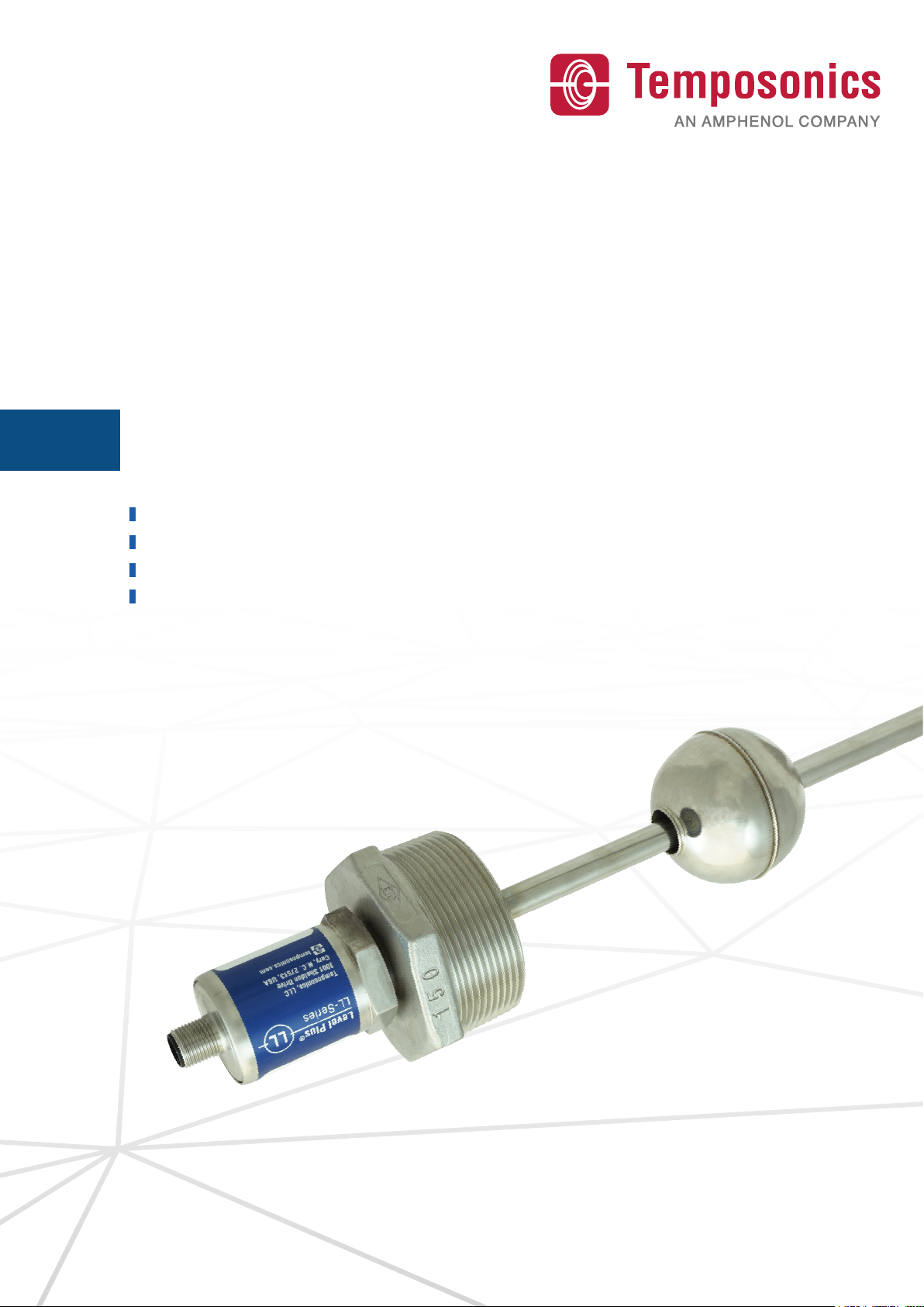
5.1 Components
The Level Plus®LLE liquid level transmitter consists of four main
components; a base model, float, adaptor, and optional temperature
measurement. Varying the components of the transmitter allows the
transmitter to be customized to almost any application.
Base Model
The base model of the LLE consist of the housing, 3/4” NPT threads,
M12 connector, and either a 7 mm or 10 mm pipe. The drawing of the
base model is shown in section 5.7 Technical Drawing.
Floats
LLE transmitters offer numerous floats for different applications such
as stainless steel for both product level and interface level. To be able
to accurately detect the interface level there needs to be a difference
of at least 0.05 in specific gravities between the product and interface
liquids. For detailed information about floats, refer to the ‘Accessories
Catalog’, (Temposonics Part # 551103).
For assistance with selecting a specific float for your application,
please contact Technical Support with the following information:
• Specific gravity of liquid(s) being measured
• Process temperature
• Process opening size
• Vessel pressure
Adaptor
The LLE is available with multiple adapters to allow for mounting of
the standard 3/4” NPT fitting into larger openings. Available adapters
include NPT fittings from 1” to 4”, ANSI flanges from 1” to 6”, SAE 5
bolt adapters, and custom flanges.
Temperature Measurement
The LLE offers an optional temperature measurement for analog
outputs models with a direct RTD output from a PT100 Class A RTD.
The RTD is located at 2" from the tip of the pipe for order lengths less
than 20" and at 10% of order length for all other lengths.
Accessories
Temposonics also offers a series of displays, housings, converters,
and other accessories, please refer to the ‘Accessories Catalog’,
(Part#551103).
5.2 Accuracy
For magnetostrictive transmitters inherent accuracy is measured
in terms of non-linearity. Non-linearity is a measurement of any
imperfections in the waveguide that are reflected in the linearity of
the transmitter’s output. Temposonics tolerances reflect a maximum
non-linearity of +/- 0.5 mm. Temposonics is able to achieve such
strict tolerances by manufacturing all of its own waveguide from a
proprietary alloy and testing 100% of all transmitters before shipping.
5.3 Warranty
Important:
Contact Technical Support or Customer Service for assistance if
you suspect that the transmitter is not working correctly. Technical
support can assist you with troubleshooting, part replacement, and
Returned Material Authorization (RMA) information if required.
All Level Plus®transmitters come with a two year limited warranty
from the factory shipment date. An additional extended warranty can
be purchased. A Return Materials Authorization (RMA) number is
required and must accompany any transmitter returns. Any unit that
was used in a process must be properly cleaned in accordance with
OSHA standards, before it is returned to the factory. A Material Safety
Data Sheet (MSDS) must also accompany the transmitter that was
used in any process.
The Temposonics obligation is limited to repair or replacement of any
defective part of the unit. No warranty can be provided for defects
that are due to improper use or above average stress of the product,
as well as for wear parts. Under no circumstances will Temposonics
accept liability in the event of offense against the warranty rules, no
matter if these have been assured or expected, even in case of fault or
negligence of the company.

Level Plus® LLE
Operation Manual
I8 I
Temposonics explicitly excludes any further warranties. Neither
the company’s representatives, agents, dealers nor employees are
authorized to increase or change the scope of warranty.
5.4 Storage
If storage is required prior to installation, store indoors in a dry
environment at ambient temperature range not to exceed −40…+71°C
(−40…+160°F).

Level Plus® LLE
Operation Manual
I9 I
5.5 Model Number Indentification
d Output - Temperature
V 1 1 T 10…0 Vdc (2 output channel) w/RTD
V 1 2 T 10…0 Vdc (2 output channel) w/RTD
A 1 1 T 20…4 mA (1 output channel) w/RTD
A 1 2 T 20…4 mA (2 output channels) w/RTD
Note: Sensor pipe H = 10 mm is required RTD at 2 in. (50 mm) if length is less than 20 in.
(508 mm). RTD at 10% of length for all other lengths.
e Process Connection Type
1NPT
6150# RF Flange
SSAE
ZCustom Flange
b Sensors pipe
G7 mm 304 SS Pipe
H10 mm 316 SS Pipe
L L E
a b c d e f g h i
a Sensor model
LL E E-Series
c Order length
X X X X M 0156…2646 mm
X X X X U 006.2…104.2 in.
.
1 2 3 4 5 6 7 8 9 10 11 12 13 14 15 16 17 18 19 20
d Output
C 4 1 1 CANopen (bus terminator), 1000 kBit/s, 20 um,
1 magnet
C 4 2 1 CANopen (bus terminator), 500 kBit/s, 20 um,
1 magnet
C 4 3 1 CANopen (bus terminator), 250 kBit/s, 20 um,
1 magnet
C 4 4 1 CANopen (bus terminator), 125 kBit/s, 20 um,
1 magnet
C 4 1 2 CANopen (bus terminator), 1000 kBit/s, 20 um,
2 magnets
C 4 2 2 CANopen (bus terminator), 500 kBit/s, 20 um,
2 magnets
C 4 3 2 CANopen (bus terminator), 250 kBit/s, 20 um,
2 magnets
C 4 4 2 CANopen (bus terminator), 125 kBit/s, 20 um,
2 magnets
See next page
f
d Output - No Temperature
V 1 1 0 10…0 Vdc (1 output channel with 1
position magnet)
V 1 2 0 10…0 Vdc (2 output channels with 2
position magnet)
A 1 1 0 20…4 mA (1 output channel with 1
position magnet)
A 1 2 0 20…4 mA (2 output channels with 2
position magnets)
L 0 0 0 IO-Link
S 1 B 0 SSI, 25 bit, Binary, 0.1 mm resolution*
S 1 G 0 SSI, 25 bit, Gray, 0.1 mm resolution*
S 2 B 0 SSI, 24 bit, Binary, 0.1 mm resolution*
S 2 G 0 SSI, 24 bit, Gray, 0.1 mm resolution*
C 3 1 1 CANopen, 1000 kBit/s, 20 um, 1 magnet
C 3 2 1 CANopen, 500 kBit/s, 20 um, 1 magnet
C 3 3 1 CANopen, 250 kBit/s, 20 um, 1 magnet
C 3 4 1 CANopen, 125 kBit/s, 20 um, 1 magnet
C 3 1 2 CANopen, 1000 kBit/s, 20 um, 2 magnets
C 3 2 2 CANopen, 500 kBit/s, 20 um, 2 magnets
C 3 3 2 CANopen, 250 kBit/s, 20 um, 2 magnets
C 3 4 2 CANopen, 125 kBit/s, 20 um, 2 magnets
*/ Measurement direction is set to measure away from housing towards tip.

Level Plus® LLE
Operation Manual
I10 I
f Process Connection Size
A3/4"
B1"
C1½"
D2"
E2½"
F3"
G4"
H5"
SSAE 5 bolt
3SAE-12
g Float 1
7 0 404834 **
7 1 404835 **
7 2 201999
1 0 561612
1 1 254886
1 2 201120
L 1 251981-2 ***
L 2 254526-2 ***
L 3 201250-2 ***
L 4 252961-2 ***
L 5 201232-2 ***
L 6 251982-2 ***
L 7 254894-2 ***
L 8 252962-2 ***
L 9 201233-2 ***
h Float 2
X X None
L 6 251982-2
L 7 254894-2
L 8 252962-2
L 9 201233-2
f Options
BStop Collar and Cable
C5 m cable
SStop Collar
XNone
**/ requires G = 7 mm pipe
***/ requires Options B or S with Stop Collar for larger I.D. floats. Not to be used with 7 mm pipe.
Manuals, Software & 3D models available at:
www.temposonics.com

Level Plus® LLE
Operation Manual
I11 I
5.6 Technical data
Level Output
Voltage 0…10 VDC or 10…0 VDC, 0…10 VDC and 10…0 VDC (controller input resistance RL > 5 kΩ)
Current 4…20 mA or 20…4 mA (minimum / maximum load: 0 / 500 Ω)
SSI (Synchronous Serial Interface) Binary or Gray, 24 or 25 bit
CANbus CANopen: CIA standard DS 301 V3.0 / encoder profile DS 406 V3.1, CAN System ISO-11898
IO-Link V1.1, 32 bit signed, COM3 (230.4 kBaud)
Measured value Product Level and/or Interface Level
Measurement parameters
Resolution 0.1 mm
Inherent accuracy +/-0.5 mm
Repeatability ≤ ±0.005 % F.S. (minimum ±20 μm)
Temperature Output
Measured Variable Single point temperature
Accuracy Class A RTD
Output PT100 RTD
Operating conditions
Operating temperature −40…+75 °C (−40…+167 °F)
Humidity 90 % relative humidity, no condensation
Ingress protection 1IP67 / IP69K (correctly fitted)
Shock test 100 g (single shock) IEC standard 60068-2-27
Vibration test 15 g / 10…2000 Hz IEC standard 60068-2-6 (resonance frequencies excluded)
EMC test Electromagnetic emission according to EN 61000-6-3
Electromagnetic immunity according to EN 61000-6-2
The sensor meets the requirements of the EU directives and is marked with
Design/Material
Sensor electronics housing/Flange Stainless steel 1.4305 (AISI 303); option: Stainless steel 1.4404 (AISI 316L)
Sensor rod 7 mm (0.28 in.) rod Ø: Stainless steel 1.4301 (AISI 304)
10 mm (0.39 in.) rod Ø: Stainless steel 1.4404 (AISI 316L)
Stroke length 156…2646 mm (6.2…104.2 in.)
Operating pressure 7 mm (0.28 in.) rod Ø: 300 bar (4351 psi), 450 bar (6527 psi) peak
10 mm (0.39 in.) rod Ø: 350 bar (5076 psi), 530 bar (7687 psi) peak
Mounting
Rigid Pipe NPT (3/4", 1", 1.5", 2", 2.5", 3", 4“), ANSI RF Flange (2", 3", 4", 5", 6") (150#, 300#, 600#)
1/ The IP rating is not part of the UL recognition
See next page
Electrical connection

Level Plus® LLE
Operation Manual
I12 I
5.7 Technical drawing
Controlling design dimensions are in millimeters and measurements in ( ) are in inches
Product float Sensor rod
Type: 7 (0.28) OD
Type: 10 (0.39) OD
Interface float Stop collar
34
(1.3)
13
(0.5)
M12 Connector
57
(2.2)
Sensor electronics housing
51
(2.0)
Null zone
50…2500
(2…100)
Measurement range
63.3
(2.5)
Inactive zone
156…2646
(6.2…104.2)
Order length
Process connection
NPT (3/4", 1", 1.5", 2", 3", 4") or
RF Flange (2", 3", 4", 5", 6")
Fig. 2: Technical drawing LLE
Electrical connection
Connection type Analog: M12 male connector (5 pin)
SSI: M12 male connector (8 pin)
IO-Link: M12 male connector (4 pin)
CAN: M12 male connector (5 pin)
Operating voltage +24 VDC (−15 / +20 %); UL recognition requires an approved power supply with energy
limitation (UL 61010-1), or Class 2 rating according to the National Electrical Code (USA) /
Canadian Electrical Code
Ripple ≤ 0.28 VPP
Current consumption Analog: 50…140 mA, SSI, CANbus & IO-Link: 60 mA
Dielectric strength 500 VDC (DC ground to machine ground)
Polarity protection Up to −30 VDC
Overvoltage protection Up to 36 VDC

Level Plus® LLE
Operation Manual
I13 I
6. Installation and mounting
6.1 Training
Installation should only be conducted by qualified service person-
nel according to local regulations or Temposonics trained service
technicians. Temposonics offers web based and in person training for
installation, commissioning, maintenance, and repair. Temposonics
also offers factory direct services for these same functions. Contact
Temposonics to discuss training or factory direct services before
starting.
6.2 Stilling wells and guide poles
Level Plus®transmitters can be mounted in slotted or unslotted stilling
wells but a slotted stilling well is always preferred. Using a unslotted
stilling well will negatively affect performance of any level device as
the level in the stilling well can differ from the level in the tank. The
Level Plus®transmitter can also be installed to one side of the stilling
well to also allow for sampling and manual gauging from the same
opening as the automatic tank gauging. Contact technical support for
details.
Level Plus®transmitters do not require a stilling well for installation.
Our transmitters are installed in numerous tanks without stilling wells
with no loss in performance due to our patented flexible waveguide
and hose. A stilling well is highly recommended for agitated, turbulent,
and/or fast filling tanks.
6.3 Tools
• Adjustable pliers
• Large pipe wrench
• Common head screwdriver, slotted screwdriver
6.4 Installation steps
Caution:
It is recommended that assembly and mounting of this transmitter
should not be done alone. To ensure proper and safe assembly
of the level transmitter, a minimum of two (2) individuals are
recommended. Gloves are also recommended. PPE may be required
for work areas such as safety shoes, safety glasses, hard hat, and
fire resistant clothing.
1. Consult chapter 4.3 before starting.
2. Perform steps 1-10 in chapter 8.4.1
3. Remove stop collars from rigid pipe.
4. Slide NPT adapter or flange onto rigid pipe and secure the
adapter/flange. To prevent damage to rigid pipe keep the adapter/
flange supported and towards the end of the level transmitter.
5. Slide the product float onto the rigid pipe. Slide the interface float
(optional) onto the rigid pipe. Install stop collar so the magnet of
the float is 64 mm (2.5 in.) from the tip of the rigid. Do not drop
float(s) or allow them to free fall along the rigid pipe as damage
may result.
NOTICE
The bottom stop collar can be removed or adjusted based on the
float selected for the application. Please consult the factory for more
information.
6. Slide float(s) and adapter or flange assembly back down to the
stop collar to prevent them from free falling during installation
into the tank. If you are using the o-ring stop collar it will not
support the weight of the adapter or flange. Insert the rigid pipe
and floats through the tank opening and lower the transmitter
float assembly into the tank until it rests on the bottom.
7. Connect the adpter or flange to the mating connector on the tank.
8. Connect the 3/4” NPT (rigid) to the adapter or flange
assembly. Tighten the NPT fitting to the adapter or flange. It is
recommended to use anti-seize on the connection.
9. Connect cable to connector.
10. Terminate the pigtail cable noting proper wire orientation. Wiring
diagram is shown in Section 7.
Consult Section 5.7 Technical Drawing to reference what the finished
installation should look like.

Level Plus® LLE
Operation Manual
I14 I
6.5 Mounting
The method of mounting the transmitter is dependent on the vessel
or tank in which it is being used, and what type of transmitter is being
mounted. For model LLE there is a NPT thread mount or flange mount.
NPT Threaded mounting
The level transmitter can be mounted directly to the tank via a NPT
threaded fitting, assuming there is a proper threaded connection
available as shown in section 5.7. If the float will not fit through the
opening, there must be some alternative means to mount the float on
the transmitter from inside the vessel; this may require an access port
nearby the entry point of the transmitter.
Drilled and tapped flange mounting
The level transmitter can be mounted directly to the tank using a
flanged opening. If the float will not fit through the flanged opening
when the flange is removed, there must be some alternative means
to mount the float on the transmitter from inside the vessel; this may
require an access port nearby the entry point of the transmitter.

Level Plus® LLE
Operation Manual
I15 I
7. Electrical connections
7.1 Basic information
Placement of installation and cabling have decisive influence on
the sensor‘s electromagnetic compatibility (EMC). Hence correct
installation of this active electronic system and the EMC of the entire
system must be ensured by using suitable metal connectors, shielded
cables and grounding. Overvoltages or faulty connections can damage
its electronics despite protection against wrong polarity.
7.2 Safety recommendations
Be sure to:
1. Always follow applicable local and national electrical codes and
observe polarity when making electrical connections.
2. Never make electrical connections to the level transmitter with
power turned on.
3. Use low-resistant twisted pair and shielded cables. Connect the
shield to ground externally via the controller equipment.
4. Keep control and sign leads separate from power cables and
sufficiently far away from motor cables, frequency inverters, valve
lines, relays, etc.
5. Use only connectors with metal housing and connect the
shielding to the connector housing.
6. Keep the connection surface at both shielding ends as large as
possible. Connect the cable clamps to function as a ground.
7. Keep all non-shielded leads as short as possible.
8. Keep the earth connection as short as possible with a large cross
section. Avoid ground loops.
9. With potential differences between machine and electronics
earth connections, no compensating currents are allowed to flow
across the cable shielding. Recommendation: Install potential
compensating leads with large cross section or use cables with
separate double shielding, and connect only one end of the shield.
10. Use only stabilized power supplies in compliance with the
specified connecting values
NOTICE
1. Do not mount the sensors in the area of strong magnetic or
electric noise fields.
2.Never connect / disconnect the sensor when voltage is applied.

Level Plus® LLE
Operation Manual
I16 I
7.3 Grounding
Earth/Machine Ground
The LLE is earth grounded through the process connection to the
tank with the assumption that the tank is grounded. If the tank is not
grounded then a ground will need to be connected to the housing of
the LLE. Without correct grounding the overvoltage protection will be
compromised.
Shield Ground
Immunity performance of the sensor from external sources of surge,
burst, RF, radiated emissions and other noise is dependent on a proper
ground for the shield of the communications cable. The communica-
tions cable shield should be of a braided type and connected to the
internals.
.
7.4 Wiring Connections
D34 Analog
Signal + power supply
M12 male connector
(A-coded) Pin Function
1
2
3
4
5
View on sensor
1+24 VDC (−15 / +20 %)
2 Output 1
3 DC Ground (0 V)
4 Output 2
5 DC Ground
D84 SSI
Signal + power supply
M12 male connector
(A-coded) Pin Function
1
4
2
6
3
5
7
View on sensor
1 Clock (+)
2Clock (−)
3 Data (+)
4Data (−)
5 Not connected
6 Not connected
7+24 VDC (−15 / +20 %)
8 DC Ground (0 V)
D34 CAN
Signal + power supply
M12 male connector
(A-coded) Pin Function
1
2
3
4
5
View on sensor
1 Shield
2+24 VDC (−15 / +20 %)
3 DC Ground (0 V)
4 CAN_H
5 CAN_L
D44 IO-Link
Signal + power supply
M12 A-coded Pin Function
2
1
4
31 +24 VDC (±25 %)
2DI/ DQ
3 DC Ground (0 V)
4C/ Q
Fig. 3: D34 Analog
Fig. 4: D84 SSI
Fig. 5: D34 CAN
Fig. 6: D44 IO-Link
T84 Analog + RTD
Signal + power supply
M12 male connector
(A-coded) Pin Function
1
4
2
6
3
5
7
View on sensor
1 Clock (+)
2Clock (−)
3 Data (+)
4Data (−)
5 Not connected
6 Not connected
7+24 VDC (−15 / +20 %)
8 DC Ground (0 V)
Fig. 7: T84 Analog + RTD

Level Plus® LLE
Operation Manual
I17 I
8.4.2 Severe Service Applications
8.4.2.1
Perform Inspection suggested in chapter 8.3.
8.4.2.2
Disconnect Power.
8.4.2.3
Disconnect process connection from tank. Remove level transmitter
from tank.
8.4.2.4
When the bottom of the pipe is reached inspect the float(s).
8.4.2.4.1
If the floats are highly contaminated then remove the assembly from
the tank and remove the floats from the pipe.
8.4.2.4.2
If the floats are slightly contaminated then clean the floats without
removing the floats from the pipe.
8.4.2.5
Add anti-seize or similar lubricant to connection to prevent daamge to
threads. Replace rigid pipe and floats in tank.
8.4.2.6
Connect process connection to tank.
8.4.2.7
Connect Power.
8.4.2.8
The process should be carried out regularly until a consistent pattern
has been established as to how long the intervals between cleanings
should be.
8. Maintaince
8.1 Training
Installation should only be conducted by qualified service personnel
according to local regulations or Temposonics trained service
technicians. Temposonics offers web based and in person training for
installation, commissioning, maintenance, and repair. Temposonics
also offers factory direct services for these same functions. Contact
Temposonics to discuss training or factory direct services before
starting.
8.2 Tools
• Adjustable wrench
• Anti-seize
8.3 Inspection
Below are some standard items that should be inspected on a
regular basis to make sure that the level transmitter and surrounding
environment are in operating condition.
• There are no visible unauthorized modifications
• Electrical connections are tight
• No obvious damage to cable
• Housing is not damaged or cracked
• No corrosion on visible parts
8.4 Preventative maintenance
The level transmitters do not typically require preventative
maintenance but may require preventative maintenance dependent
on the application. For general purpose applications where there is
no potential for buildup on the pipe and/or float there is no need for
preventative maintenance but routine inspection is still suggested.
For severe service applications where there is potential for buildup on
the pipe and/or float then preventative maintenance is required.
8.4.1 General purpose applications
8.4.1.1
Perform Inspection suggested in chapter 8.3.
8.4.1.2
It is suggested to disconnect the process connection between the tank
and the level transmitter and anti-seize or similar lubricant to prevent
damage to threads.
8.4.1.3
No additional preventative maintenance is necessary. Preventative
maintenance suggested for Severe Service Applications may be
performed.
NOTE
It is best to clean the pipe as it is removed from the tank to minimize
the amount of product that is removed from the tank. The user
should take caution and abide by all regulations so that product is
not spilled and the environment is not contaminated.

Level Plus® LLE
Operation Manual
I18 I
9. Repair
9.1 RMA policy
Important:
Contact Technical Support or Customer Service for assistance if
you suspect that the transmitter is not working correctly. Technical
support can assist you with troubleshooting, part replacement, and
Returned Material Authorization (RMA) information if required.
All Level Plus®transmitters come with a two year limited warranty
from the factory shipment date. A Return Materials Authorization
(RMA) number is required and must accompany any transmitter
returns. Any unit that was used in a process must be properly cleaned
in accordance with OSHA standards, before it is returned to the
factory. A Material Safety Data Sheet (MSDS) must also accompany
the transmitter that was used in any process.
9.2 Training
Repair should only be conducted by qualified service personnel
according to local regulations or Temposonics trained service
technicians. Temposonics offers web based and in person training for
installation, commissioning, maintenance, and repair. Temposonics
also offers factory direct services for these same functions. Contact
Temposonics to discuss training or factory direct services before
starting.
9.3 Troubleshooting
Symptom Possible cause Action
No
communication
with transmitter
No power Check voltage at
transmitter
Wiring incorrect Reference wiring
connections, chapter
7.4
Wrong protocol Conrm software and
transmitter are same
protocol
Fig. 8: Troubleshooting reference

Level Plus® LLE
Operation Manual
I19 I
Fig. 9: Spare parts
10. Spare Parts
Below are the spare parts list for the LLE that are included as part of
the model number. Please contact Temposonics Technical Support
with any questions.
11. Interface
11.1 Analog output
The analog output for LLE is either single output or dual output
dependent on the order code. The output codes starting with V are
voltage outputs and the codes starting with A are current outputs. The
first digit is the voltage or current closest to the head and the second
is closet to the tip. For example, A010 4..20mA has the 4mA set point
closest to the head and 20 mA closest to the tip. The analog output
cannot be adjusted.
Stop Collar Part number
7 mm O-ring 562354
10 mm O-ring 562355
7 mm stop collar 562392
10 mm stop collar 562348
Cable Part number
Analog 370675
IO-Link 370675
CANopen 370675
SSI 370676
Process Connection Part number
SAE 5 Bolt 404205
1 “ NPT 562349-1
1,5 “ NPT 562349-2
2 “ NPT 562349-3
2,5 " NPT 562349-4
3 " NPT 562349-5
4 " NPT 562349-3
2 " 150# RF Flange 560465-1
3 " 150# RF Flange 560465-2
4 " 150# RF Flange 560465-3
5 " 150# RF Flange 560465-4
6 " 150# RF Flange 560465-5
11.2 IO-Link output
IO-Link is an open standard according to IEC 61131-9. It is a serial,
bi-directional point-to-point connection for signal transmission and
energy supply. The bi-directional communication enables consistent
communication between sensors and the controller as well as
consistent diagnostic information down to the sensor level. For
additional details on setup please consult the EH IO Link manual
551485 section 5.
The measurement direction of IO Link can be programmed by the
customer. The Parameter Measuring Direction, Index 0x73, can be set
to False to measure from the housing to the tip of the pipe or True to
measure from the tip of the pipe to the housing.
11.3 SSI output
The SSI output is available as either 24 or 25 bit, Binary or Gray code,
and 0.1 mm resolution. The measurement direction is set to measure
up from the tip of the pipe.
11.4 CANopen output
CANbus (Controller Area Network) is designed for high-speed data
exchange at machine level. CAN is a vendor independent open
fieldbus system, based on standard ISO 11898. CAN specifies the
functional and technical parameters with which the intelligent digital
automation devices can be networked via a master-slave serial link
by using a communication profile. Protocol architecture of functional
and applications data is oriented to the OSI reference model (ISO
7498). Bus technology is administrated and developed by the user
organisation CiA (CAN in Automation)
The CANOpen output of the LLE is avaialbe with or without integral
termination, selectable Baud rate of 1000, 500, 250, or 125 kBit/s.
The resolution is set at 0.02 mm and the output can be configured for
1 or 2 floats. The measurement direction is set to measure away from
the electronic housing and towards the tip of the pipe

UNITED STATES
Temposonics, LLC
Americas & APAC Region
3001 Sheldon Drive
Cary, N.C. 27513
Phone: +1 919 677-0100
E-mail: [email protected]
GERMANY
Temposonics
GmbH & Co. KG
EMEA Region & India
Auf dem Schüffel 9
58513 Lüdenscheid
Phone: +49 2351 9587-0
E-mail: [email protected]
ITALY
Branch Of ce
Phone: +39 030 988 3819
E-mail: [email protected]
FRANCE
Branch Of ce
Phone: +33 6 14 060 728
E-mail: [email protected]
UK
Branch Of ce
Phone: +44 79 44 15 03 00
E-mail: [email protected]
SCANDINAVIA
Branch Of ce
Phone: + 46 70 29 91 281
E-mail: [email protected]
CHINA
Branch Of ce
Phone: +86 21 2415 1000 / 2415 1001
E-mail: [email protected]
JAPAN
Branch Of ce
Phone: +81 3 6416 1063
E-mail: [email protected]
temposonics.com
© 2022 Temposonics, LLC – all rights reserved. Temposonics, LLC and Temposonics GmbH & Co. KG are subsidiaries of Amphenol Corporation. Except for any third party marks for
which attribution is provided herein, the company names and product names used in this document may be the registered trademarks or unregistered trademarks of Temposonics, LLC or
Temposonics GmbH & Co. KG. Detailed trademark ownership information is available at www.temposonics.com/trademarkownership.
Document Part Number:
552101 Revision A (EN) 05/2022
Table of contents
Other Amphenol Transmitter manuals