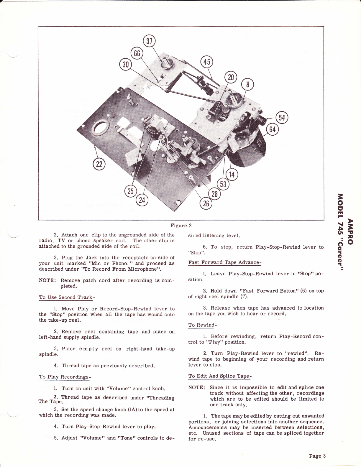
2. Forbestresults, cuttape at a slight diagonal,
join ends together with splicing tape on the glossy side
and trim off any excessive width.
E rasing Recorded Material-
When the Play-Record knob (3) is in the "Record"
position, the erase head is automatically in operation,
erasing any previous recording before a new one is
made. You may erase material no longer needed,
without recording, by moving the Play-Record knob
(3) to "Record" on turning the "Volume" control knob
to the minimum volume position just before the record-
er shuts off. Onetrack is erased at a time, To erase
the second track, reverse the reels and repeat the
above operation.
To Use Recorder As A Public Address System-
Plug microphone cord into I'Mic. or Phonoil re-
ceptacle. Turn Play-Record controlto I'phono-record"
position. Be sure microphone is far enough away from
speaker to avoid feedback squeal. Volume may be ad-
justed with Volume eontrol. Mikeand/or radio-phono
can be simultaneously used for blending of special
effects in public address use with Ampro Dual - Input
Mixer, No. 133.
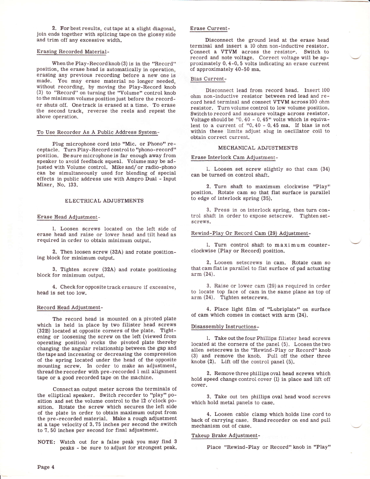
ELECTRICAL ADJUSTMENTS
Erase Head Adjustment-
I, Loosen screws located on the left side of
erase head and raise or lower head and tilt head as
required in order to obtain minimum output.
2. Then loosen screw (32A) and rotate position-
ing block for minimum output.
3. Tighten screw (32A) and rotate positioning
block for minimum output.
4, Checkfor oppositetrackerasure if excessive,
head is set too low.
Record Head Adjustment-
The record head is mounted on a pivoted plate
which is held in place by two filister head screws
(32B) located at opposite corners of the plate. Tight-
ening or loosening the screw on the left (viewed from
operating position) rocks the pivoted plate thereby
changing the angular relationship between the gap and
thetapeand increasing or decreasing the compression
oI the spring located under the head of the opposite
mounting screw. In order to make an adjustment,
threadtherecorder with pre-recorded 1 mil alignment
tape or a good recorded tape on the machine.
Connect an output meter across the terminals of
the elliptical speaker. Switch recorder to "play" po-
sition and set the volume control to the 12 o'clock po-
sition. Rotate the screw which secures the left side
of the plate in order to obtain maximum output from
the pre-recorded material. Make a rough adjustment
at a tape velocityof 3. ?5 inches per second the switch
to ?.50 inches per second for final adjustment.
NOTE: Watch out for a false peak you may find 3
peaks - be sure to adjust for strongest peak.
Page 4
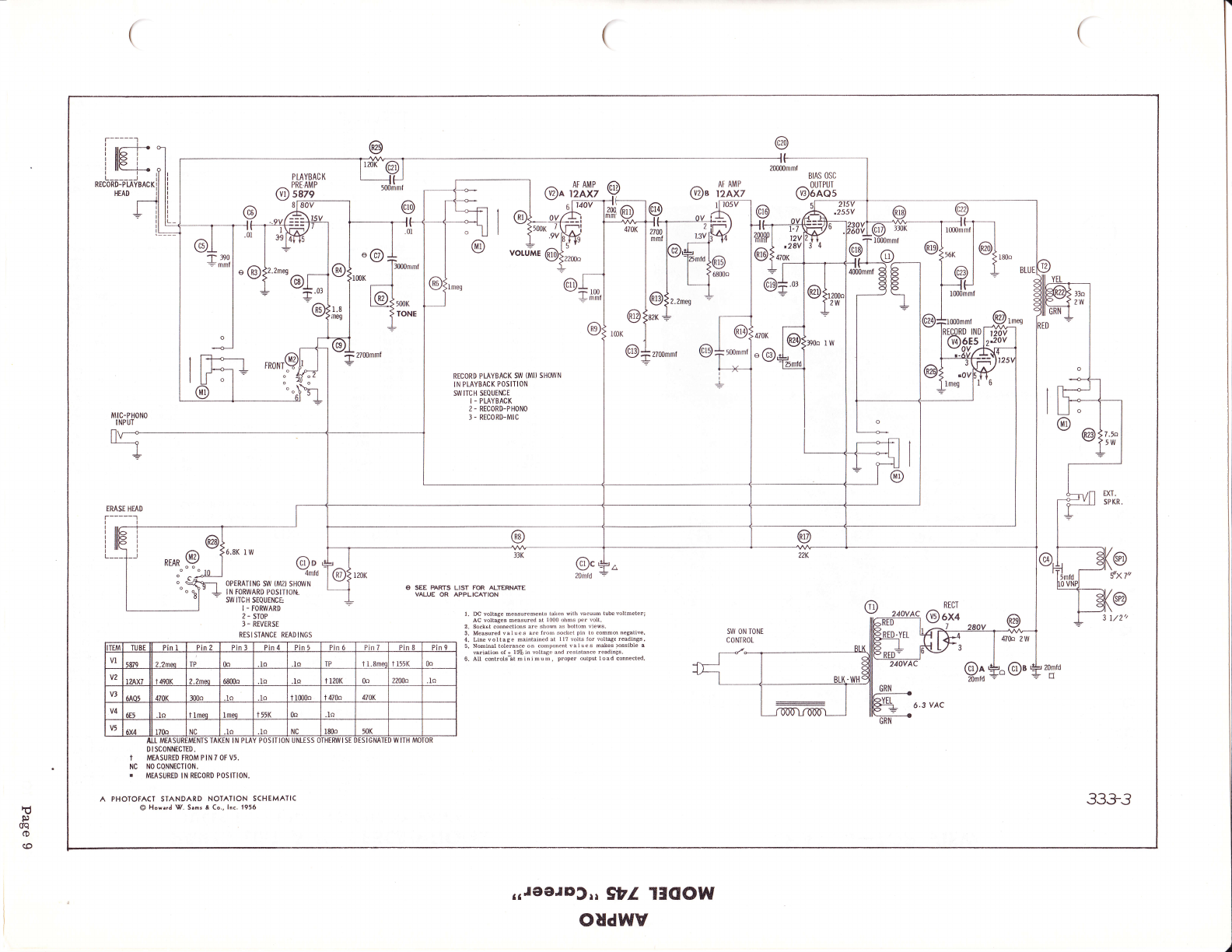
Erase Current-
Disconnect the ground lead at the erase head
terminal and insert a 10 ohm non-inductive resistor.
Qonnect a VTVM across the resistor. Switch to
record and note voltage. Correct voltage will be ap-
proximately 0,4-0. 5 volts indicating an erase current
of approximately 40-50 ma.
Bias Current-
Disconnect lead from record head. Insert 100
ohm non-inductive resistor between red lead and re-
cord head terminal and connect VTVM acrossl00 ohm
resistor. Turnvolume control to low volume position.
Switchtorecord and measure voltage across resistor.
Voltage shouldbe "0.40 - 0,45" volts which is equiva-
lent to a current of "0.40 - 0.45 ma. If bias is not
within these limits adjust slug in oscillator coil to
obtain correct current.
MECHANICAL ADJUSTMENTS
Erase Interlock Cam Adjustment-
l. Loosen set screw slightly so that cam (34)
can be turned on control shajt.
2. Turn shaft to maximum clockwise t'Playt'
position. Rotate cam so that flat surface is parallel
to edge of interlock spring (35).
3. Press in on interlock spring, then turn con-
trol shaft in order to expose setscrew. Tighten set-
screws.
Rewind-Play Or Record Cam (29) Adjustment-
1. Turn control shaJt to maximum counter-
clockwise (Play or Record) position.
2. Loosen setscrews in cam. Rotate cam so
thatcamflatis parallel to flat surface of pad actuating
arm (24).
3. Raise or lower cam (29) as required in order
to locate top face of cam in the same plane as top of
arm (24). Tighten setscrews.
4. Place light film of "Lubriplate" on surface
of cam which comes in contact with arm (24).
Disassembly Instructions-
1. Take outthe four Phillips filister head screws
located at the corners of the panel (5). Loosenthetwo
allen setscrews in the "Rewind-Play or Recordl knob
(3) and remove the knob. Puli off the other three
knobs (2). Lift off the control panel (5).
2. Removethreephillipsoval head screws which
hold speed change control cover (l) in place and lift off
cover.
3. Take out ten phillips oval head wood screws
which hold metal panels to case.
4. Loosen cable clamp which holds line cord to
back of carrying case. Standrecorder on end and pull
mechanism out of case.
Takeup Brake Adjustment-
Place "Rewind-Play or Recordtt knob in [Playtt
t-