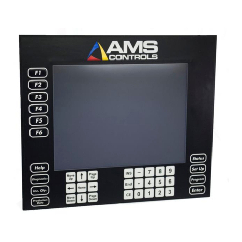
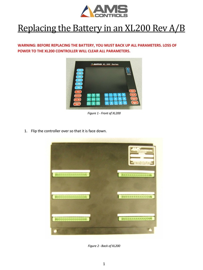
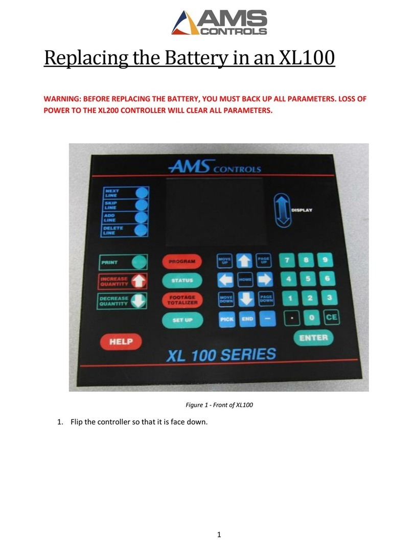
AMS Controls MP328CL User manual

AMS Controls 1MP328CL Controller
5/23/2012 Gripper
Model
MP328CL
Closed Loop Backgauge Controller
Reference Manual
Chapter 1 ____________________________________ Introduction
Chapter 2 ___________________________________ Specification
Chapter 3 _____________________________ Product Description
Chapter 4 _____________________________________ Installation
Chapter 5 _____________________________Operating Procedure
Chapter 6 _____________________________In Case of a Problem
Appendix A______________________________Setup Data Sheets
Appendix B_______________________________ Mounting Details
Appendix C______________________ Electrical Interface Diagram

AMS Controls 2MP328CL Controller
5/23/2012 Gripper
MP328CL Gripper Controller
AMS Controls has been supplying length control systems to the
metal fabricating industry since 1978 and has built a reputation of
producing high quality and reliable controllers.
The MP328CL Gripper controller is a cost effective controller
designed to perform multiple bends on a sheet of metal and will
use a gripping function to hold the metal and to sequence it
through each bend..
The MP328CL is housed in a compact 8.00” x 12.50” wide x
2.25” deep enclosure and requires a single 24 VDC power supply
for operation.
RUN
HALT
SET
*
PRG
ENT
7
8
9
4
5
6
1
2
3
0
CE
•
MP300 SERIES
LENGTH CONTROL SYSTEMS
CYCLE
UP

AMS Controls 3MP328CL Controller
5/23/2012 Gripper
Front Panel Components and Description
The Model MP328CL front panel has three push button switches,
a 16 key keypad, and a two line 48 character liquid crystal
display.
The three push buttons provide the following functions:
•CYCLE This push button will open the gripper jaws and
will reset the sequence
•RUN Press to initiate an automatic move sequence
•HALT Press to manually stop the guide movement
The keys provide the following functions:
•SETUP Press to enter the setup mode. The setup
mode is used to enter specific parameters
about the Gripper.
•∗Press the asterisk key to exit the setup or
programming modes. Also known as the
STATUS key to display current position, etc.
•PRG Press to program a new set position. While in
the program mode, the new position will flash.
•ENT Press to store the values entered in the setup
and program modes.
•CE Press to clear an incorrect entry value before
the “ENT” key is pressed. Also used to clear
any errors reported by the controller.
Setup Mode
Note: The following descriptions include all possible
SETUP PARAMETERS and there are some parameters that
are not used for every application. Only use the ones that
apply for your particular machine.

AMS Controls 4MP328CL Controller
5/23/2012 Gripper
The SETUP mode is used when the MP328CL is initially installed
to configure it to the particular characteristics of the Gripper. The
SETUP mode is entered by pressing the “Set Up” key and the
mode can be exited by pressing the “∗” key. When power is
applied to the controller, the built-in diagnostics check the
memory for data retention.
If an error is detected, the memory is automatically cleared and
the SETUP mode is entered to indicate that this data should be
reentered. The setup values are entered in the order shown
below and an explanation of each parameter is given. A form is
provided in the back of this manual for recording the setup
parameters of your machine. This form should be completed
after your machine has been installed and properly adjusted.
To enter the SETUP mode, press the “Set Up” key. The
following display will appear.
Selec
ting
“1”
will allow the operator to adjust the following parameters:
Reference Mode
The REFERENCE MODE parameter tells the MP328CL where
the reference switch is located. The reference point is the center
of the brake where the bend occurs. If the switch is close to the
reference point and most of the moves of the Gripper occur
“behind” the switch, the REFERENCE MODE is NEAR. If the
switch is behind the Gripper and most of the moves are in “front”
of the switch, the REFERENCE MODE is FAR. Use any number
key to toggle the choices.
The switch for a NEAR REFERENCE MODE must be normally
closed and remain open as long as the Gripper is on the switch
or closer to the reference point than the switch. The switch for a
FAR REFERENCE MODE must be normally open and remain
closed as long as the Gripper is on the switch or farther away
from the reference point than the switch.
1=Configure 2=In/Out
3=Loc/Remote 4=Reference

AMS Controls 5MP328CL Controller
5/23/2012 Gripper
Ref. Pos.
The REFERENCE POSITION is the distance from the reference
point to the inside jaws of the gripper after being referenced.
Lip Size
If this parameter is greater than zero, a lip will be added to the
beginning of each sheet. The acceptable range of values are
0.0000” to 50.0000”.
Metal Flow
This parameter specifies whether the metal is fed from one side
of the brake and the formed parts comes out of the other
(NORMAL); or if it is fed through the backside of the brake,
(REVERSE). If this parameter is set to NORMAL, the machine
should move to the total sheet length plus the CLEARANCE
DISTANCE when there is a new program. When REVERSE is
selected, it will move to the new CLEARANCE DISTANCE.
Clearance Dist
This parameter determines the point at which the gripper will
move to when a new program is entered or after completion of a
sequence. CLEARANCE DIST plus ACTUAL PART LENGTH
will determine the position of the guide between sequences.
Brake Dwell Dn
BRAKE DWELL DOWN is the time it takes for the brake to move
from the top of the stroke to the bottom of the stroke. The range
of time allowed is 0.001 to 9.999 seconds and can be set to the
nearest millisecond.
Brake Dwell Up
BRAKE DWELL UP is the time necessary for the brake to return
from the bottom to the top of its stroke
NOTE:
If the LOOP ENABLE input is used while the brake is
activated, the LOOP ENABLE input must be reactivated
before the total BRAKE DWELL (down and up) is completed.

AMS Controls 6MP328CL Controller
5/23/2012 Gripper
Loop Gain
LOOP GAIN is a parameter which sets the sensitivity of the servo
loop. Lowering this number will make the drive less responsive.
Raising this number will make the system move sensitive and
responsive. If the LOOP GAIN is too high, the system will
become unstable and oscillate.
Great care should be used in changing this number. Make
gradual changes.
The acceptable range of values for this parameter is 0.100
through 500.00 and the default value is 1.000
Jog Velocity
The JOG VELOCITY sets the speed that the line moves during
jogging, referencing, and calibration, measured in feet per minute
(FPM). The accepted range of values for this parameter is 1
FPM through 50 FPM and the default value is 10 FPM.
Max Velocity
The MAX VELOCITY parameter sets the maximum speed
(speed used during the RUN sequence), in FPM.
Acceleration
ACCELERATION sets the rate of change of velocity in inches per
second, per second (inches/second)2. This parameter controls
both the acceleration and deceleration of the travel. The
accepted range of values for this parameter is 1 In/S2 through
3500 In/S2, and the default value is 10 In/S2.
Offset Volts (Auto)
The OFFSET VOLTS is the voltage required to cause the
positioning system to come to a complete stop. This parameter
is automatically adjusted by the AMS controller but it can be
changed by the user when the loop is not enabled. This would
only be done if the initial value if grossly off, and it would take too
long for the controller to integrate out the error. The more
common usage of this parameter is for monitoring the amount of
offset and making external adjustments to the drive. This
parameter should be kept as close to zero as possible to give the
controller the maximum control range.

AMS Controls 7MP328CL Controller
5/23/2012 Gripper
Offset Integral
The OFFSET INTEGRAL defines the integral time constant for
the removal of position error (drift), when the closed loop servo
system attempt to hold the line in a locked position. An OFFSET
INTEGRAL time constant of 100 seconds is recommended.
Derivative
On systems that use hydraulics or have a lot of inertia, it is
possible that the system may have a slow response time. If this
is the case, it may be possible to have a faster response by
entering a DERIVATIVE value. The sluggish response of the
machine will result in an error, and the purpose of the
DERIVATIVE is to anticipate the rate of change in the error, and
amplify the rate of change to improve performance.
If it is determined that this parameter is to be used, start with a
value of 10 seconds (or less), and then decrease the value until a
change in pitch or “hum” is heard in the motor which indicates
that the controller is overcorrecting the error. When this occurs,
increase the value until the system stops oscillating.
CAUTION:
Changing this value will amplify any noise in the system, as
well as the error, which can cause problems in the system.
This parameter may also increase the tolerance of the
system which could cause variation errors. Entering a zero
for DERIVATIVE will disable the parameter.
Tolerance
On the machine, the controller can check for the Gripper to be
within a specified TOLERANCE before activating the brake. If
the machine has not stopped within this TOLERANCE, the
controller will halt and an error will be displayed.
The TOLERANCE should be set small enough to get acceptable
parts but wide enough to avoid production interruptions. The
controller allows values from 0.0005 inches to 10.0000 inches.
The default value for TOLERANCE is 1.0000 inches.

AMS Controls 8MP328CL Controller
5/23/2012 Gripper
Grip Delay
The GRIP DELAY is a delay that can be entered into the
controller to adjust for the gripper hitting the part, and the part
bouncing off of the gripper so that the jaws of the gripper do not
grab the part properly. When the part enters the jaws of the
gripper it will activate the gripper so that the jaws will clamp down
on the part. A small delay can be entered so that the jaws do not
close immediately. The acceptable range of values for this
parameter is 0.0 to 5.0 seconds.
Resolution
The RESOLUTION parameter defines the length of the Gripper
movement for each increment of the motor encoder. It is a
function of the distance traveled by the gripper during one
revolution of the motor encoder, and the number of counts per
revolution of the motor encoder. The formula for calculating
RESOLUTION is as follows:
Resolution =Distance of Gripper movement
4 x Encoder Count
The encoder used will typically be a motor encoder or an encoder
mounted in such as way as to simulate the motor movement.
Correction (TO BE SPECIFIED)
The CORRECTION FACTOR adjusts for errors in the GRIPPER
movement. It is expressed as a percentage, with 100% being no
correction. Increasing the CORRECTION FACTOR causes the
GRIPPER movement to become longer and decreasing the value
shrinks the GRIPPER movement.
Calculate the CORRECTION FACTOR using the following steps:
1) Make the GRIPPER move to the same position ten times and
take an accurate measurement of this value (OR) 2) Bend a
piece of metal each of the ten times that the GRIPPER moves.
3) Find the average length by adding up all ten measurements
and dividing by ten. 4) Use the following formula for the new
CORRECTION FACTOR, using the average of the ten parts for
"actual measured position.":
New CORR. FACTOR = (Programmed Length ÷Actual
Measured Position) x Old CORR. FACTOR

AMS Controls 9MP328CL Controller
5/23/2012 Gripper
Filter Constant
The FILTER CONSTANT can be adjusted in order to improve
accuracy. A low value should be used on machines with very
stable line speeds. A high value (greater than 50 Hz) should be
used when rapid fluctuations in line speeds occur. Some trial
may be necessary to achieve an accurate value. The default
value is 32 Hz, which is considered to be on the high side of the
low values. The controller will allow values from 1.0 Hz to 200.0
Hz.
Units
Length measurements can be programmed and displayed as
either English inches, Metric millimeters, or Metric centimeters.
Press any number key to toggle through the choices.
Pressing the “∗” key will show the current “Set Position” and
“Current Position”. If the “Set Up” key is pressed again other
options are available.
If “2” is pressed, the INPUT/OUTPUT screen can be viewed.
This can be helpful as a troubleshooting aid if the machine is not
working properly.
1=Configure 2=In/Out
3=Loc/Remote 4=Reference
In: _ _ _ _ _ _ _ _
Out: _ _ 3 _ _ _ _ _

AMS Controls 10 MP328CL Controller
5/23/2012 Gripper
Pressing the “Set Up” key will allow you to exit this screen.
Pressing “3” while viewing the SETUP screen enters the
LOCAL/REMOTE function. If the programming for the machine
is to be done with this controller, select the LOCAL mode. If
another controller will program the machine, select REMOTE.
Selecting “4” while viewing the SETUP screen, will cause you to
enter the REFERENCE mode. The machine will immediately
locate the reference switch and then stop. This is done to set a
REFERENCE for the machine. If this is not manually done, it will
automatically find the reference switch when RUN is pressed.
Referencing
The controller must be referenced to a known position each time
power is removed and restored to the unit. The fixed reference
point will be a home switch.
Near referencing with a home switch:
1. The MP328CL determines the state of the Home Switch. If
the switch is OPEN, skip to step # 3.
2. The MP328CL moves the gauge in the forward direction until
the Home Switch is OPEN. It then skips to step # 5.
3. The controller moves the gauge in the reverse direction until
the Home Switch is CLOSED.
4. The MP328CL moves the gauge in the forward direction until
the Home Switch is OPEN.
5. At the CLOSED -> OPEN transition of the Home Switch, the
encoder interrupt captures the encoder count and sets it
equal to the reference position.
Far referencing with a home switch:
1. The MP328CL determines the state of the Home Switch. If
the switch is OPEN, the controller moves the gauge in the
reverse direction until the Home Switch is CLOSED.
2. The controller moves the gauge in the forward direction until
the Home Switch is OPEN.
3. The MP328CL moves the gauge in the reverse direction until
the Home Switch is CLOSED.
4. At the OPEN -> CLOSED transition of the Home Switch, the
encoder interrupt captures the encoder count and sets it
equal to the reference position.

AMS Controls 11 MP328CL Controller
5/23/2012 Gripper
NOTES:
•If near referencing is used, the home switch must be
wired N/C (normally closed). Far referencing requires
that normally open contacts be used.

AMS Controls 12 MP328CL Controller
5/23/2012 Gripper
If the “Set Up” key is pressed twice, the following screen
appears:
While in the second SETUP screen, pressing “1” will test the
communications with another controller if they are interfaced
together. If there is no communications, the messages “No Data
Received” and “No Data Sent” will be seen.
Pressing “2” while in the second SETUP screen allows the
controller to perform a calibration of the machine automatically.
If you enter a calibration value, the machine will move to that
point and prompt the operator for a measured value to that point.
The machine will then calculate the correction value and ask the
operator if they want this value updated.
(THIS MAY CHANGE!!)
Program Mode
The program mode is entered by pressing the “PRG” key. The
part “type” will start to flash, indicating that the controller is
waiting for the entry of the new type of part that is to be made.
The operator need only to press any number key to toggle
through the choices, and press the “ENT” key to lock the
selection in., the choices are:
- Single Piece. Only the lip is bent, if programmed.
L L-Shaped. Two bends are made (including the lip).
U U-Shaped. Three bends (including the lip).
0 Full wrapper. One piece is made that is bent four
times (with the lip), to form a complete section of duct.
After the TYPE is selected, the HEIGHT and WIDTH
measurements can then be entered. Again use the “ENT” key to
lock the selection in. Only height will be used for (-) type parts.
PROGRAM SCREEN
1= Test Communications
2=Auto Calibrate
S 0 Loc Bnd 0/3 0.00”
Type : 0 50.00” x 35.00”

AMS Controls 13 MP328CL Controller
5/23/2012 Gripper
After the part is programmed, the STATUS screen will be shown,
listing the line velocity, whether the controller is in the LOCAL or
REMOTE mode, the current bend that is being made, the current
position, the part TYPE, and the part dimensions.
STATUS SCREEN
Run Operation
With this style of machine, the gripper has a sheet detect switch.
When the run button is first pressed, and there is no sheet in the
gripper, the controller should move the gripper in until the sheet
is found, and engage the gripper. When the run button is
pressed and a sheet is detected by the gripper, the controller
should grip the metal, if it has not already, position to the first
bend, engage the brake (wait for the dwell time), then move to
the next position. When all bends are made, it should return to
the clearance position (as programmed in the configuration).
Type Height Width
-- 0.00” 0.00”
Gripper
Brake
Sheet

AMS Controls 14 MP328CL Controller
5/23/2012 Gripper
When part information is programmed, and the RUN button is
pressed the gripper will try to find the part in the forward
direction. As long as the programmed part is shorter than the
clearance position, the part will be processed. If the part is
physically longer than the clearance position, the gripper must be
jogged back to allow the part to be accepted. This must be done
on the first part of that length, and the machine will readjust itself
for the remaining parts.
If “metal flow” is set to NORMAL, the home position will be at the
total sheet size plus the clearance distance. If it is REVERSE,
then the home position is at the clearance distance only. In the
first case, the operator will be placing a sheet on a transfer table
in front of the brake. The clearance position of the gripper should
be far enough away so that it will not interfere with the operator
Move to the home
position
New Program
Done
Run
Move in until
switch is on or at
end of the table
Is the gripper
switch on?
No
Engage gripper
Done
Engage gripper
Move to the next
position
Turn the brake on
Wait for dwell dn
Turn the brake off
Wait for dwell up
Last move?
Move to home
Done
Yes
No

AMS Controls 15 MP328CL Controller
5/23/2012 Gripper
putting the sheet on the table. In the second case, the sheet is
fed from the other side of the brake into the gripper. As soon as
the gripper “sees” the metal, it clamps. Because of this
arrangement, it is necessary to feed the metal only a short
distance.

AMS Controls 16 MP328CL Controller
5/23/2012 Gripper
MP328CL Switch Settings
Switch Description
1 Unit ID Must be OFF
2 Unit ID Must be ON
3 Unit ID Must be ON
4 Analog Polarity
5 Encoder Direction
6 Not Used Must be OFF
7 Unit ID Must be OFF
The proper Unit ID switch setting for the MP328CL is: switches 2
and 3 ON. Some systems have the capability of having 2
MP328CLs, and the Unit ID switch setting for the second
controller is: switches 1, 2, and 3 ON.
MP328CL Inputs/Outputs
Inputs Description
1 Jog Forward
2 Jog Reverse
3 Home
4 Run Enable
5 Setup/Lockout
6 E-Stop
7 Sheet Detect
8 Loop Enable
Outputs Description
1 Drive Enable
2 Not Used
3 Not Used
4 Run
5 No Brake
6 Not Used
7 Gripper
8 Brake
Pin 14 Analog +
Pin 15 Analog -

AMS Controls 17 MP328CL Controller
5/23/2012 Gripper
Mounting Details
Figure B-1. Panel Mount Mounting Dimensions
REVISIONS
TOLERANCES
DECIMAL
FRACTIONAL
ANGULAR
NO.
DATE
BY
A
B
C
D
E
TITLE
DRAWN BY
CHK'D
FILE
APP'D
DATE
SCALE
MATERIAL
DRAWING NO.
APPLIED MICROSYSTEMS
NOTES:
PANEL CUTOUT
11 7/8"
12 1/2"
7 3/8"
8"
11 1/2"
7"
11 1/2" X 7"
OPTIMUM
VIEWING
ANGLE
2 1/4"
DASHED LINE IS EDGE OF PANEL
(REFERENCE)
MP300 MOUNTING DIMENSIONS
3804
DRILL 1/4" HOLE
MJA
10-29-91
3/16"
3/16"
3/16"
3/16"
Table of contents
Other AMS Controls Controllers manuals

AMS Controls
AMS Controls XL200 Series User manual

AMS Controls
AMS Controls XL200 Series Use and care manual

AMS Controls
AMS Controls XL200 Series Installation manual

AMS Controls
AMS Controls XL200 Series Use and care manual

AMS Controls
AMS Controls XL100 Use and care manual

AMS Controls
AMS Controls XL200 ECO 1263 Use and care manual

AMS Controls
AMS Controls MP450S User manual

AMS Controls
AMS Controls XL200 Series Use and care manual

AMS Controls
AMS Controls MP450 User manual