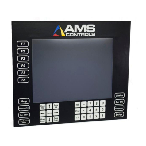
AMS Controls XL200 Series Installation manual

Flash Wizard Programming Instructions
for XL200 Controllers
Updated 5.12.2012

Flash Wizard Programming Instructions
2
Table of Contents
Required Equipment ..................................................................................................................................... 3
XL200 Series Software and Hardware Versions............................................................................................ 3
Latest Release by Version ......................................................................................................................... 3
What does the software version number mean?................................................................................. 4
XL200 Series Software Flashing Procedure................................................................................................... 4
Flashing Software by Revision and Version .................................................................................................. 6
V1& V2 Software for Rev. A Hardware ..................................................................................................... 6
V1& V2 Software for Rev. B Hardware ................................................................................................... 16
V3 Software for Rev. C Hardware ........................................................................................................... 23
V4 Software for Rev. D Hardware...........................................................................................................30

Flash Wizard Programming Instructions
3
Required Equipment
•Windows PC or laptop computer
•“Straight-through” RS232 programming cable (or USB-to-RS232)
oNo longer than 6’ (1.8 M)
oRS232 pintout
2 – 2
3 – 3
5 – 5
•XL200 Series machine controller
•24VDC Power
XL200 Series Software and Hardware Versions
The XL200 Series machine controller can be field flashed with new software versions, and it can be
flashed with different software models. The software model and version supported by any XL200
controller depends on the hardware revision of the unit.
As products are developed, tested, and then subjected to the realities of a manufacturing environment -
improvements are made in terms of reliability and performance. New features and functions desired by
customers are added and refined.
The process of evolving hardware is tracked by a Revision Letter at AMS Controls. In terms of the XL200
Series machine controller, there is a CPU Board Revision Letter and an Input/Output (I/O) Board Revision
Letter. The CPU board dictates the highest software version supported by a particular unit, and the I/O
board revision indicates whether the unit supports open loop software, closed loop software, or both.
Rev. A & B I/O boards could only support open loop or closed loop, but not both. This means if you own
a XL200 controller with a Rev. A or Rev. B I/O board, you must have AMS change out the board in order
to go from open loop to closed loop software, or closed loop to open loop software.
All I/O boards Rev. C and later support both open loop and closed loop software. You need only flash the
unit with the desired software model.
CPU Board
Hardware Revision
Software Version
Rev. A & B
V1 & 2
Rev. C
V3
Rev. D
V4
Latest Release by Version
Software versions 1 and 2 are no longer supported or developed. Versions 3 and 4 are currently
supported and are being developed concurrently for most features. Some features will show up in

Flash Wizard Programming Instructions
4
version 4 software that will never be available in version 3 software, due to the limitations of the older
hardware revision (this was also the case between v2 and v3).
Major Software
Version Number
Final Release Version
V1
V1.11 (open loop models), V1.13 (closed loop models)
V2
V2.71.01 (all models)
V3
Check with AMS for latest version
V4
Check with AMS for latest version
What does the software version number mean?
Software versions are expressed as 3 sets of numbers separated by “points” (.). The first number refers
to the major software version and often ties the version to a specific hardware revision. The second
number is a major release version. Every so often, the Engineering Department at AMS generates a “new
release” that includes any new developments, features, functions and bug fixes since the last release.
The last number is a maintenance release version, usually created in situations where a customer is
experiencing a serious bug that affects production, or has paid for a new feature that they desire
immediately.
4.12.04
Major Version
Number
Major Release
Number
Maintenance
Release Number
Software Version Breakdown
XL200 Series Software Flashing Procedure
Before attempting to flash a XL200 Series machine controller, users must contact AMS Controls for the
appropriate flash file. The Flash Wizard software will usually be included in what is sent, or it can be
downloaded from the AMS Controls website.
In order to create a flash file, AMS Technical Support Specialists must know the hardware version,
current software model, desired software model, software version, and serial number of the controller
to be flashed. Often, the Specialist can find most of this information with only the serial number of the
controller, assuming adequate records have been kept and updated.

Flash Wizard Programming Instructions
5
XL200 controllers currently loaded with Version 1 software can only be tracked by serial number in
terms of their hardware revisions. Version 1 software did not display the controller’s hardware
information to the user.
Version 2 and higher software models display all their pertinent information in a single menu –
Diagnostics\System Information. Normally, only the software model and serial number will be required
by the Specialist at AMS. If records were lost or improperly updated, a digital picture of the System
Information screen showing the Model, Serial Number, and hardware revision numbers might be
required.
XL200 System Information Menu
When the flashing software and new flash file are received, the flash file name should match the new
software model, version and serial number. For instance, XL212_v3_45_01_sn7505.FMF.

Flash Wizard Programming Instructions
6
Flashing Software by Revision and Version
Different software versions and hardware revisions have slightly different procedures. Please verify your
specific hardware and software versions to be sure you’re using the correct procedure.
Authorization codes were always required by the original XL200 Flash Program software. Later, Flash
Wizard was created and would often allow the user to program the XL200 Series machine controller
without the need for an authorization code.
Flash Wizard does not require an authorization code if the software model does not change. That is, if
the controller’s software version is the only change, no code is required. If the software model will
change with the flash, the user will be required to contact AMS Controls for an authorization code,
unless AMS was contacted for the flash file, originally. Technical Support Specialists can embed the
controller’s serial number in the flash file so that Flash Wizard will not prompt for an authorization
code.
V1& V2 Software for Rev. A Hardware
The first hardware generation of XL200 Series controllers required a different flashing program in order
to change controller software model. The XL200 Flash Program was required, and this program always
required the user to get an authorization code from AMS Controls. The code could not be generated
ahead of time. The user must begin the flash process at the controller, receive a “flash code”, contact
AMS Controls with that code, and wait for an authorization code to be generated and sent back.
To flash a controller with Rev. A hardware:
***WARNING***
On Rev. A hardware models, the controller must not lose power or lose communication with the
laptop during this process. If this occurs, you might not be able to recover and the unit will have to be
shipped to AMS Controls to be re-flashed.
1. Remove power from the XL200 Series machine controller.
2. If the XL200 is on an Eclipse network, disconnect the B connector from the back of the XL200
controller before continuing with the flash process.

Flash Wizard Programming Instructions
7
3. Connect the laptop to the XL200 using the RS232 cable. The laptop should be plugged into AC
power. Most laptops switch to a “low power” mode when running on battery power. This can
interfere with Com Port communication.
The RS232 cable should plug into the 9 pin port on top of the XL200 controller.
RS232 Port
4. Start the XL200 Flash Program software. It will probably state “Comport not open”, since the
software defaults to COM 2, and most laptops do not have a COM 2.
XL200 Flash Program Software

Flash Wizard Programming Instructions
8
5. Using the textbox in the lower left-hand corner, change the com port to an existing port on the
laptop and press the Tab key on the laptop keyboard.
Flash Program Software Pointed to Valid Com Port
6. On the XL200 Series controller, turn DIP switch 10 to the ON position. This puts the XL200 into
Program Flash Memory mode the next time it’s powered up.
DIP Switches on Top of XL200

Flash Wizard Programming Instructions
9
7. Apply 24 VDC to the XL200 CPU inputs (A1, A2). The XL200 should power up with a blue screen
with white lettering that reads “XL200 Program Flash Memory”. Whatever appears on the XL200
screen should also appear in the XL200 Flash Program software screen, indicating the laptop and
XL200 are connected and communicating with each other.
Note: The information in the following screenshot might not exactly match the data you see
displayed on your laptop. This is normal.
Controller Connected and Communicating to Software

Flash Wizard Programming Instructions
10
8. Click the Program button. The software will present the Open dialog box so that the correct
flash file can be selected.
Open Dialog Allows Correct Flash File to be Selected

Flash Wizard Programming Instructions
11
9. Navigate to the desired flash file and select it through the Open Dialog box.
Flash File Selected and Ready to Open

Flash Wizard Programming Instructions
12
10. Click the Open button. The XL200 Flash Program should immediately display a code, and is now
waiting for an Authorization Code.
Code Required to Generate Authorization Code

Flash Wizard Programming Instructions
13
11. Contact AMS Controls for the return authorization code. Enter the authorization code in the text
boxes provided and click the Enter button. The flash process should begin. It typically takes
about 20 minutes to complete programming.
Erasing Flash Memory before Programming New File

Flash Wizard Programming Instructions
14
12. Once the flash process is complete, the message “Intel Hex File has been successfully loaded.”
At this point, the XL200 Flash Program software can be closed.
Flash Programming Completed
13. Turn off power to the XL200 controller.
14. Disconnect the RS232 programming cable from the controller.
15. Re-connect the B connector if it was removed in Step 5.
16. Turn off DIP switch 10 on the top of the controller.
17. Turn on power to the controller. Answer whatever on-screen prompts are required to fully boot
the unit to the Status menu.
18. Turn controller power off.
19. Press and hold the number “5” key on the keypad. While holding the “5” key down, re-apply
power to the unit. Continue holding the “5” key until the following message is displayed:

Flash Wizard Programming Instructions
15
Clearing Memory after Flashing
20. Select the option for “Clear ALL Memory” and navigate to the OK button. Press the Enter key on
the keypad.
21. Once the controller reboots, re-enter the unit’s Eclipse data and let Eclipse download
parameters, jobs, etc. into the controller. If the XL200 is not connected to Eclipse parameters,
jobs, etc. must be re-entered by hand.

Flash Wizard Programming Instructions
16
V1& V2 Software for Rev. B Hardware
XL200 Series machine controllers with Rev. B hardware could be flashed with v1 or v2 software using the
Flash Wizard program from AMS Controls. Flash Wizard is free software that can be downloaded from
the AMS Controls website. Typically, a Technical Support Specialist will include a copy of Flash Wizard
with the file to be flashed into the controller.
When using Flash Wizard, a Technical Support Specialist can embed the unit’s serial number in the flash
file when it’s created. If this is done, the user will not be required to obtain an authorization code from
AMS Controls. If this is not done, the user must begin the flash process in order to receive an
authentication code. This code is given to a Technical Support Specialist who will generate the
authorization code.
To flash a controller with Rev. B hardware:
***WARNING***
On Rev. B hardware models, the controller must not lose power or lose communication with the
laptop during this process. If this occurs, you might not be able to recover and the unit will have to be
shipped to AMS Controls to be re-flashed.
1. Remove power from the XL200 Series machine controller.
2. If the XL200 is on an Eclipse network, disconnect the B connector from the back of the XL200
controller before continuing with the flash process.
3. Connect the laptop to the XL200 using the RS232 cable. The laptop should be plugged into AC
power. Most laptops switch to a “low power” mode when running on battery power. This can
interfere with Com Port communication.
The RS232 cable should plug into the 9 pin port on top of the XL200 controller.
RS232 Port

Flash Wizard Programming Instructions
17
4. Start the Flash Wizard software.
Flash Wizard software
5. If this is the first time running Flash Wizard on the current laptop/PC, then navigate to
Setup\Port on the menu bar to configure the software for the correct communications port.
Otherwise, skip to Step 6.
Only the port number should change in the dialog. The other settings are default, and will
always be correct for flashing a XL200 Series machine controller.
Port Setup Menu

Flash Wizard Programming Instructions
18
6. On the XL200 Series controller, turn DIP switch 10 to the ON position. This puts the XL200 into
Program Flash Memory mode the next time it’s powered up.
DIP Switches on Top of XL200
7. With the XL200 and laptop connected and Flash Wizard already running on the laptop, apply
power the controller. The XL200 will boot to a blue screen with white lettering XL200 Program
Flash Memory with some additional information specific to the controller. Whatever appears on
the controller’s screen should also appear in the Flash Wizard window.
Flash Wizard Displays Same Information as XL200

Flash Wizard Programming Instructions
19
8. Navigate to File\Flash XL200 Series. The Open dialog box will appear.
Open Dialog Allows Correct Flash File to be Selected
9. Navigate to the desired flash file and select it through the Open Dialog box.
Flash File Selected and Ready to Open

Flash Wizard Programming Instructions
20
10. Click the Open button and Flash Wizard will begin the flash process. If the purpose of the flash is
to change software models, the user must obtain a file from AMS Controls that has the
controller’s serial number embedded within the flash file, or an authorization code will be
required.
Existing Flash Programming is Erased Before New Flash Programming Begins
Other manuals for XL200 Series
4
Table of contents
Other AMS Controls Controllers manuals

AMS Controls
AMS Controls XL200 ECO 1263 Use and care manual

AMS Controls
AMS Controls XL200 Series Use and care manual

AMS Controls
AMS Controls MP450S User manual

AMS Controls
AMS Controls XL200 Series User manual

AMS Controls
AMS Controls XL200 Series Use and care manual

AMS Controls
AMS Controls XL100 Use and care manual

AMS Controls
AMS Controls MP450 User manual

AMS Controls
AMS Controls MP328CL User manual

AMS Controls
AMS Controls XL200 Series Use and care manual