Revision 1.11/ 02/18/2014
Application Note –AS5000 Programmer
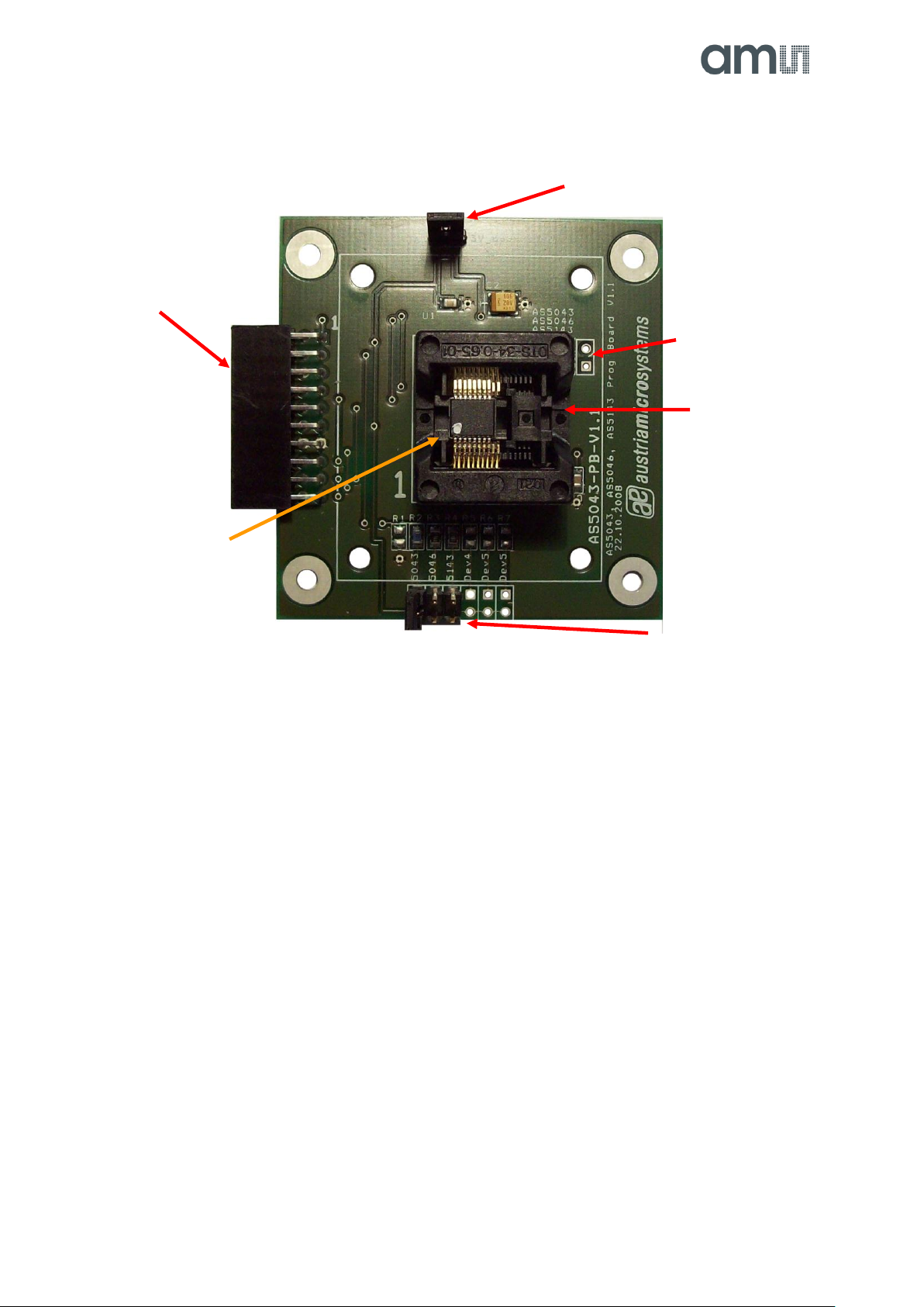
4.1 Programming the AS5043
Programming AS5043 encoders requires the AS5043-PB
ZIF socket board.
Jumper J6 must be close for normal operation and
programming operation.
Figure 9: AS5043-PB Programming board
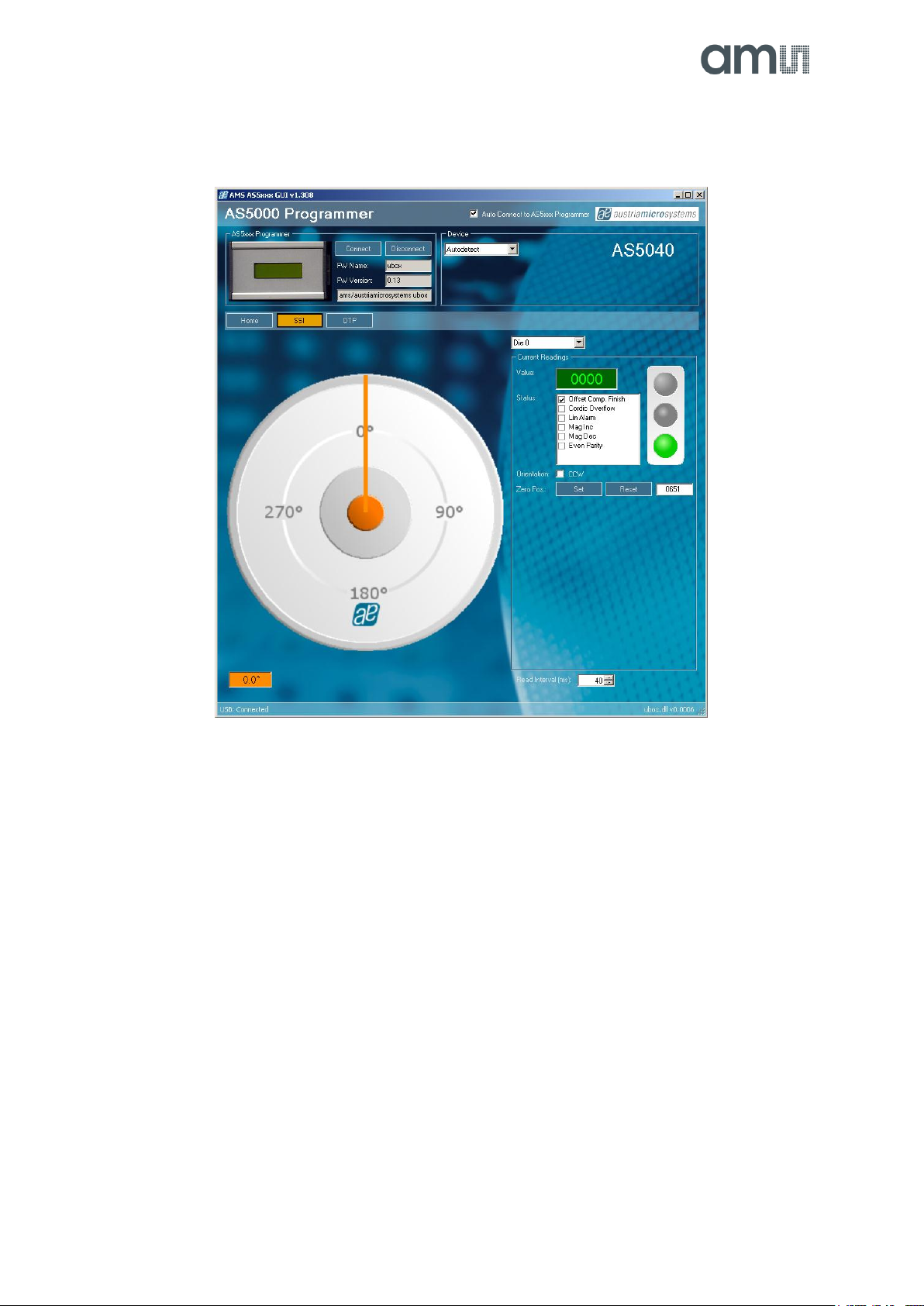
By selecting the SSI tab, information of the angular position and the status bits appear:
Figure 10: SSI tab with AS 5043 inserted in AS5043 -PB
-Die selection: This option is for dual die AS52xx devices only. For AS50xx and AS51xx devices Die 0 (default)
must be selected.
-Value field is the raw angle extracted from the SSI stream. The angle range is 0 (0°) to 1023 (359.6°)
-Status field displays the status bits extracted from the SSI stream. Green light means that the airgap between the
magnet and encoder is correct. Orange light means the magnet is too close of too far.
-CCW checkbox is the angle direction. To invert the rotating direction, check CCW.
-Zero Position field: Set button writes the actual angle value into the Zero Position register of the encoder. This
programming is not permanent. The actual value will be 0 after zero position programming. To reset the zero
position register, or to set a new zero position, click on Reset first.
-Read interval is the SSI stream readout and refresh rate the GUI.
Status bits and field alarm
a
Set the actual angle as
Zero Position
Selected die
(dual die AS52xx devices only)
AS5043-PB ZIF socket board
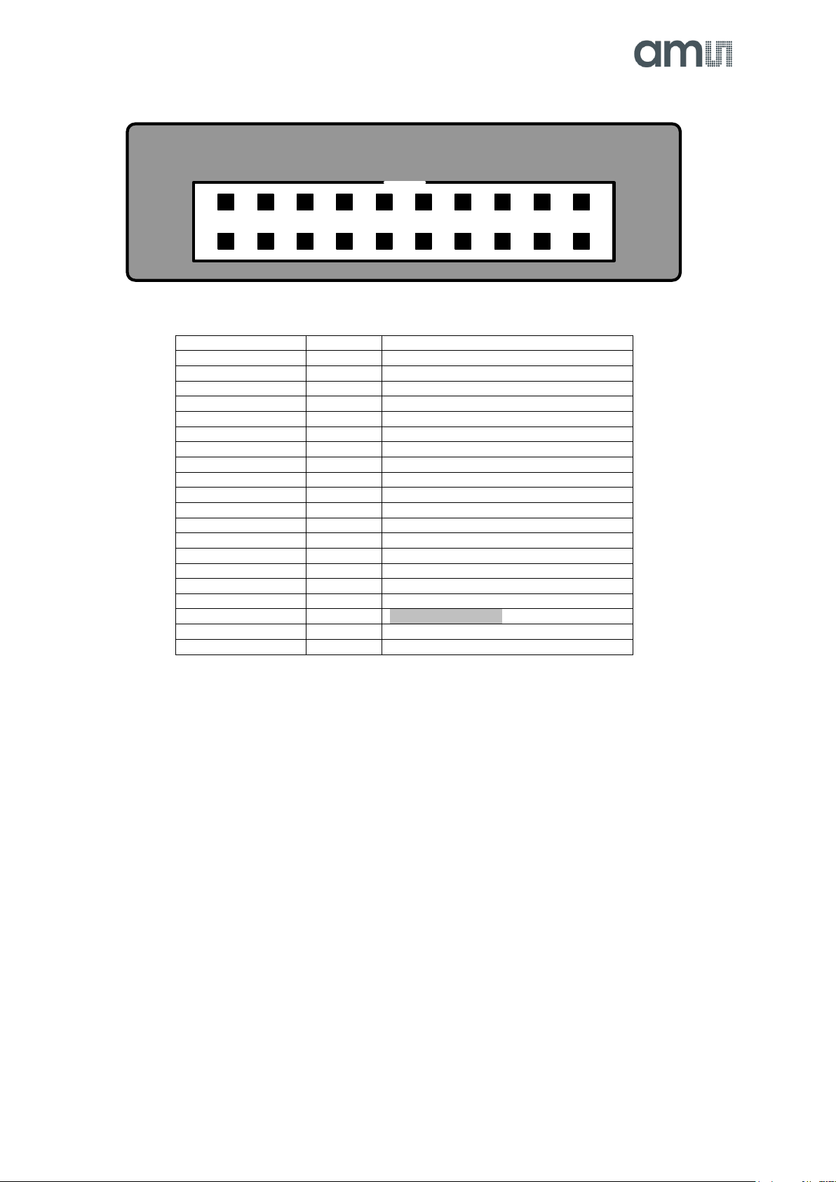
Device selection for autodetect:
-Jumper position 1: AS5043