AMS AS3935 User manual

AS3935 Standard Board
ams Demo Kit Manual, Confidential
Page 2
[v1-03] 2014-Jul-08
Document Feedback
Table of Contents
1Features............................................................................................................................... 3
1.1 Programmable Lightning Sensor AS3935 Key Features..................................................... 3
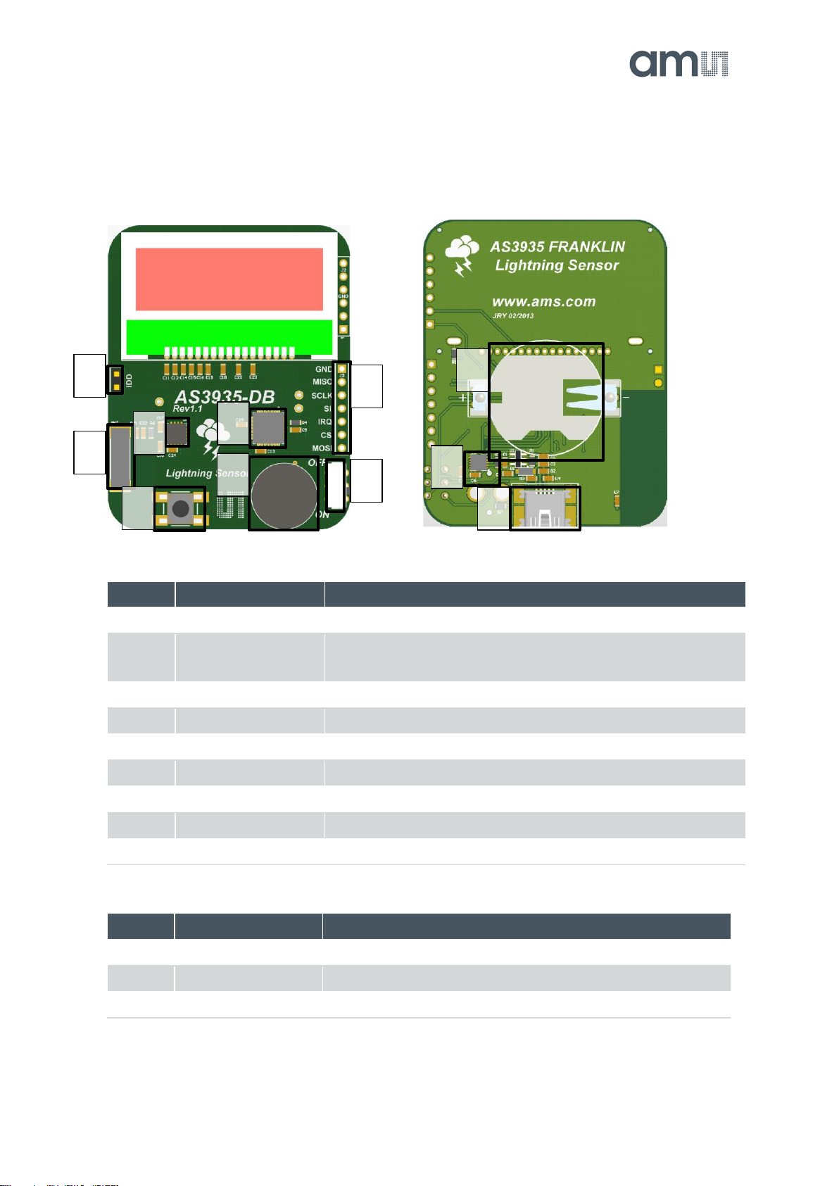
2Franklin Lightning Sensor Description ................................................................................. 4
2.1 Board Description................................................................................................................. 4
2.2 Component Description Top ................................................................................................ 4
2.3 Component Description Bottom........................................................................................... 4
2.4 Buzzer.................................................................................................................................. 5
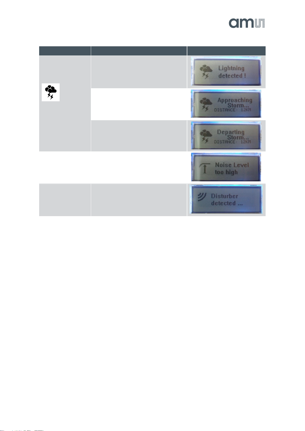
2.5 LCD...................................................................................................................................... 5
2.6 Real Time Clock (RTC)........................................................................................................ 6
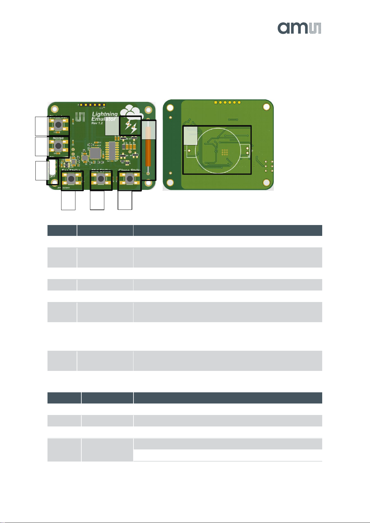
3Lightning Emulator............................................................................................................... 7
3.1 Board Description................................................................................................................. 7
3.2 Lightning Emulator Description............................................................................................ 7
3.3 LEDs .................................................................................................................................... 7
4How to get started with Franklin Lightning Sensor Demo Kit .............................................. 8
5GUI Description.................................................................................................................... 9
6History Description............................................................................................................. 12
7Layer Stack of Lightning Sensor........................................................................................ 13
8Layout Recommendations ................................................................................................. 13
9Schematic, Layout and BOM of Lightning Sensor............................................................. 14
9.1 Schematic of Lightning Sensor Demo Board.....................................................................14
9.2 Board Layout of Lightning Sensor Demo Board ................................................................ 15
9.3 Bill of Material of Lightning Sensor Demo Board............................................................... 16
10 Schematic, Layout and BOM of Lightning Emulator.......................................................... 17
10.1 Schematic of Lightning Emulator ....................................................................................... 17
10.2 Board Layout of Lightning Emulator................................................................................... 18
10.3 Bill of Material of Lightning Emulator .................................................................................19
11 Ordering & Contact Information .........................................................................................20
12 Copyrights & Disclaimer.....................................................................................................21
13 Revision Information ..........................................................................................................22

AS3935 Standard Board
ams Demo Kit Manual, Confidential
Page 3
[v1-03] 2014-Jul-08
Document Feedback
1 Features
Fully operational Lightning Sensor
Supplied by a 3V CR2032 battery with long battery life time >1000 hours
Buzzer alarm for early warning of storm
128x32 display with blue backlight for detail information about storm warning
Automatic antenna and RCO tuning implemented
USB connection for adjusting AS3935 detail settings
Handheld Lightning Emulator
Emulation of lightning with different distance (far, close, closest) and noise generation
1.1 Programmable Lightning Sensor AS3935 Key Features
Lightning Sensor warns of lightning storm activity within a radius of 40km
Distance estimation to the head of the storm down to 1km
Detects both cloud-to-ground and intra-cloud (cloud-to-cloud) flashes
Embedded man-made disturber rejection algorithm
Programmable detection levels enable threshold setting for optimal controls
SPI and I²C interface is used for control and register reading
Antenna tuning to compensate variations of the external components
Supply voltage range 2.4V to 5.5V
Power-down, listening, and active mode

AS3935 Standard Board
ams Demo Kit Manual, Confidential
Page 4
[v1-03] 2014-Jul-08
Document Feedback
2 Franklin Lightning Sensor Description
2.1 Board Description
Figure 1: Lightning Sensor –Top and Bottom view
2.2 Component Description Top
Label
Name
Info
A
ON/OFF
Power on/off the Demo Board.
B
BUTTON
Short Press: The actual time of the RTC is shown.
Long Press (>1s): The statistics of the AS3935 is cleared
C
IDD
IDD Jumper for current measurement of AS3935
D
BUZZER
Audio Information for Lightning and Disturber
E
LCD
128x32 Display, blue backlight
F
500kHz
100uH LF Antenna for AS3935
G
AS3935
Lightning Sensor
H
MCU
Microcontroller PIC24FJ64GB002
I
AS3935 Interface
SPI Interface to AS3935
2.3 Component Description Bottom
Label
Name
Info
J
USB-CONNECTOR
USB Interface for the GUI
K
AS1362, AS1746
Power Management; Analog Switch
L
CR2032 Battery
Insert CR2032 Coin Cell here
C
G
F
B
D
H
I
A
L
K
J

AS3935 Standard Board
ams Demo Kit Manual, Confidential
Page 5
[v1-03] 2014-Jul-08
Document Feedback
2.4 Buzzer
Label
Modulation
Info
D
1x500ms ON
Lightning detected
2x150ms ON
Lightning detected: Distance to the previous lightning has
changed
4x50ms ON
Disturber detected
Note: The buzzer alarm can be modified or turned off via the GUI
2.5 LCD
Label
Description
Sign
Booting
After power on of the demo board, the
austriamicrosystems logo and the
firmware version will be displayed.
Antenna Tuning
After start-up the antenna of the
AS3935 is automatically tuned. The
tuning uses the internal array of
capacitors to achieve 500kHz as
resonance frequency. The resonance
frequency and the internal capacitance
are shown on the LCD.
RCOs Calibration
After the antenna tuning the internal
RC-Oscillators are calibrated. The
SRCO is calibrated to 32kHz and the
TRCO is calibrated to 1.1MHz. Both
frequencies are displayed.
USB connected
The demo board can be connected via
USB. As soon as the USB bus is
connected the sensor is turned off and
all settings of the AS3935 can be saved
in the GUI. If the demo board is power
cycled when the USB plug is already
connected, the LCO and RCO
calibration is not executed, in order to
allow the user to do those calibrations
via the GUI.
Listening Mode
After the calibration, the Lightning
sensor is set in listening mode. No
storm is within detection range.

AS3935 Standard Board
ams Demo Kit Manual, Confidential
Page 6
[v1-03] 2014-Jul-08
Document Feedback
Label
Description
Sign
Lightning
This symbol
indicates a lightning
–the text give
further information.
Lightning has been detected. The
distance estimation and movement of
the head of the storm is shown
afterwards.
The distance to the head of the storm
decreases.
The distance to the head of the storm
increases.
Noise Floor
Detected
Continuous noise is jamming the
AS3935 AFE; during this time the
sensor cannot detect the presence of
lightning activities.
Disturber Detected
Disturbers have been received by the
AS3935 and rejected by the disturber
rejection embedded algorithm.
2.6 Real Time Clock (RTC)
The demo board has a built in RTC that must be synchronized with a PC. Once the RTC is set to
the current time, it is possible to create timestamps for detected lightning events. The
synchronization via the GUI is explained in section Error! Reference source not found..
Note: The RTC is reset to midnight of 1. January 2012 and the history is cleared when the demo
board is switched off and on again.

AS3935 Standard Board
ams Demo Kit Manual, Confidential
Page 7
[v1-03] 2014-Jul-08
Document Feedback
3 Lightning Emulator
3.1 Board Description
Figure 1: Lightning Emulator –Top and Bottom View
3.2 Lightning Emulator Description
Label
Name
Info
A
Disturber
Emulates a disturber on the antenna; red LED is flashing up
B
Noise
Emulates noise on the antenna; red LED keeps flashing as long
as noise signals are emulated (3s)
C
Far Strike
Emulates a pattern of a lightning with far distance
D
Mid Strike
Emulates a pattern of a lightning with closer distance
E
Close Strike
Emulates a pattern of a lightning with the closest distance
F
Antenna
The different patterns are modulated on the 500kHz carrier that is
transmitted via the LF antenna.
G
On/Off Switch
Turn both switches to ON to supply the lightning emulator; As
soon as the demo board is switched on, the ON LED flashes up
once a second to indicate being turned on.
H
Battery holder
CR2450
The Lightning Emulator board is supplied with a CR2450 Coin
Cell.
3.3 LEDs
Label
Name
Info
G
ON
Blue LED flashes up once a second
A
Disturber
Red LED flashes up in case a disturber is emulated
B
Noise
Red LED flashes up for 3s in case noise is emulated
J
Strike
Yellow LED flashes up in case far strike is emulated
Orange LED flashes up in case mid strike is emulated
A
B
A
C
D
E
J
F
H
G

AS3935 Standard Board
ams Demo Kit Manual, Confidential
Page 8
[v1-03] 2014-Jul-08
Document Feedback
Label
Name
Info
Red LED flashes up in case close strike is emulated
4 How to get started with Franklin Lightning Sensor Demo Kit
Due to the sensitive nature of the sensor towards noise and disturbers a separate
application note is provided. It explains the operational environment and board placement
for which the demonstration will work as intended. This information is given in the
application note “AS3935_AppNote_AN03_DemoKit_Setup_EN_v1.pdf”.
Insert the 3V battery (CR2032) in the battery holder “C”on the AS3935 demo board.
Insert a 3V battery in the battery holder “G”on the Lightning Emulator.
Position the lightning emulator and the AS3935 demo board in such a way that both antennas
are in parallel to each other. Keep a distance of 10-15 cm between both boards.
Turn on the AS3935 Lightning Sensor via the ON/OFF –switch “A”. When you switch on the
board you will see on the LCD the austriamicrosystems logo followed by the LCO and the RCO
calibration. After successful calibration the AS3935 goes into sense mode awaiting a lightning.
Note: The LCO should be tuned to 500 kHz, the TRCO to 1.1 MHz and the SRCO to 32 kHz.
To manually execute the tuning procedures connect the USB plug before turning the demo
board on via switch “A”.
Turn on the Lightning Emulator via the ON/OFF –switch “F”. When turned on, the blue LED
will be continuously flashing.
Note: Make sure the battery of the Lightning Emulator is full. Otherwise lightning might not be
emulated correctly.
Now you can start to press the switches “Far Strike”, “Mid Strike” and “Close Strike” (button “B”,
“C”, and “D”)on the Emulator, simulating lightning events that will be detected by the sensor.
The display will flash up showing the signs described above and the buzzer will trigger an
alarm.
If a disturber is emulated (button “A”) the AS3935 demo board will show “Disturber detected”.

AS3935 Standard Board
ams Demo Kit Manual, Confidential
Page 9
[v1-03] 2014-Jul-08
Document Feedback
5 GUI Description
Install the GUI and start the software. As soon as the demo board is connected the USB and
AS3935 Symbol in the corner becomes green.
The LCD will show the USB connection and the sensor is turned off.
Figure 2: GUI of the AS3935 Lightning Sensor
The following parameters can be defined on the AS3935 Lightning Sensor:
Power Down
In power down mode (R0<0>=1), the entire AS3935 is switched off. The typical current
consumption is 800nA. After power up, the TRCO is not calibrated. The calibration must be
done by the user pressing the button “Calibrate RCOs”, and respectively “Calibrate LCO” if
needed.
LNA Settings
The LNA settings have to be changed according to the location of the lightning sensor
(outdoor vs. indoor) as described in the AS3935 datasheet.
Noise Floor
The threshold for the trigger of the noise floor interrupt can be selected via this drop down
menu. A bigger value sets the threshold higher.

AS3935 Standard Board
ams Demo Kit Manual, Confidential
Page 10
[v1-03] 2014-Jul-08
Document Feedback
Disturber
If the disturbers are masked, no interrupts will occur if a disturber is detected.
Disturber Rejection Settings
With the watchdog threshold level WDTH (R1<3:0>) it is possible to increase the
robustness to disturbers. The AS3935 is also capable of rejecting impulse signals, like
spikes, picked up by the antenna. The spike rejection can be improved via the SREJ Level
defined in R2<3:0>. By default, R2<3:0> = 0x2. Larger values of SREJ correspond to more
robust spike rejection.
Minimum Number of Strikes
It is possible to program the AS3935 to only issue lightning interrupts if a minimum number
of lightning events are detected in a 15 minute time frame. This field allows setting it to 1, 5,
9 or 16 minimum numbers of lightning events. Once this threshold is reached the Lightning
Sensor will display every further detected lightning event.
Oscillators
In case the AS3935 demo board is connected to the GUI via USB before powering up the
demo board, the oscillators will not be calibrated. The calibration procedure can be
executed manually via the GUI. The first step is to measure the default resonance
frequency of the oscillators by pressing “Measure”. The oscillators will show inaccurate
values. Pressing “Calibrate LCO” will tune the antenna to 500 kHz, which will then allow the
user to calibrate the RCOs by pressing “Calibrate RCOs”. The added tuning caps will be
shown below. See the tuning sequence below:
Measure default values
Calibrate LCO
Calibrate RCOs
Buzzer Control
The buzzer alarm can be modified for lightning only or can be completely turned off. The
buzzer settings can be saved.
Save Settings / Restore Default Settings
All settings of the AS3935 and the buzzer can be saved by pressing “Save Settings”. To
reset the values to the factory settings press “Restore Default Settings”.
Firmware Update
In order to update the firmware, open Help →Firmware Update (Ctrl+F) and select the new
firmware revision.
Show History
The history of the occurred strikes can be read out via the GUI and saved to a log file.
Register Map
The entire register map can be readout via View→Register Map (Ctrl+M) and can be
modified by clicking on the register entries.

AS3935 Standard Board
ams Demo Kit Manual, Confidential
Page 12
[v1-03] 2014-Jul-08
Document Feedback
6 History Description
The demo board offers a volatile history that can be read out and its data can be saved into a log
file.
Figure 4: Lightning History Window
The history works as follows:
It is possible to synchronize the RTC of the board with the time of your PC pressing “Sync
RTC and Delete History”. The existing history in the memory is automatically deleted. A
short pressing of the button "B" on the Lightning Sensor demo board shows the actual time
on the LCD display.
Note: Right after every power up of the board the RTC is set to midnight of 1.January 2012.
The history is deleted when the board is turned off.
Each event detected by the Lightning Sensor is saved into the memory. It is possible to
read out the history by connecting to the GUI and pressing the button “Read History”. The
graph shows the estimated distance to the head of the storm over time.
Zoom into the history by holding your left mouse button pressed.
Zoom out of the history by pressing the right mouse button.
Select some strikes in the graph and the details will be highlighted in the table below.

AS3935 Standard Board
ams Demo Kit Manual, Confidential
Page 13
[v1-03] 2014-Jul-08
Document Feedback
All data can be exported into a log file by pressing “Export History”.
It is possible to save a maximum of 190 lightning events in the memory. If the memory is full
a notice will be displayed on the LCD to read out and delete the history. Please apply then
“Read History”,“Export History” and “Sync RTC and Delete History”.
7 Layer Stack of Lightning Sensor
Figure 5: Layer Stack of PCB
PCB Material: FR4 1mm for Active Tag. FR4 1.6mm for base station
2 layer board
Solder surface: chemical - tin
Width of copper: 35µm
Silk screen top/bottom: white
8 Layout Recommendations
Do not cross the SPI lines with the sensitive inputs of the antenna.
Below the 500 kHz LF antenna there should not be a GND plane.
Make sure that the GND plane is routed carefully.
Do not run SPI or any other interface on 500 kHz clock speed, in order to avoid cross-coupling.

AS3935 Standard Board
ams Demo Kit Manual, Confidential
Page 20
[v1-03] 2014-Jul-08
Document Feedback
11 Ordering & Contact Information
Ordering Code
Description
AS3935 DK
AS3935 Demo Kit Standard Board
Buy our products or get free samples online at:
www.ams.com/ICdirect
Technical Support is available at:
www.ams.com/Technical-Support
Provide feedback about this document at:
www.ams.com/Document-Feedback
For further information and requests, e-mail us at:
ams_sales@ams.com
For sales offices, distributors and representatives, please visit:
www.ams.com/contact
Headquarters
ams AG
Tobelbaderstrasse 30
8141 Unterpremstaetten
Austria, Europe
Tel: +43 (0) 3136 500 0
Website: www.ams.com
Table of contents
Other AMS Motherboard manuals

AMS
AMS TDC-GPX2 User manual

AMS
AMS AS6204 User manual

AMS
AMS AS7265 Series Multispectral Chipset User manual

AMS
AMS AS726x-iSPI User manual

AMS
AMS TMF882X User manual

AMS
AMS AS621 Series User manual

AMS
AMS AS3460 User manual

AMS
AMS TMD2636 EVM User manual

AMS
AMS TSL2540 EVM User manual

AMS
AMS AS7058 User manual

AMS
AMS TSL2772 EVM User manual

AMS
AMS TSL2521 User manual

AMS
AMS Radon AS3993 Installation and operating instructions

AMS
AMS AS5000 User manual

AMS
AMS AS5600 User manual

AMS
AMS USB I&P Box User manual

AMS
AMS AS5 47D-TO EK ST Series User manual

AMS
AMS AS5048 Eval-Kit Manual

AMS
AMS AS5270-MF_EK_SB User manual

AMS
AMS AS3933 Operating and installation instructions