AMS GP30-DEV-KIT User manual

User Guide
UG000292
TDC-GP30
Reference Board
GP30-DEV-KIT
v1-00 •2019-Feb-26

Document Feedback
TDC-GP30
Content Guide
Demo Kit Manual •PUBLIC
UG000292 •v1-00 • 2019-Feb-26
40 │2
Content Guide
1Introduction....................................3
1.1 Kit Content.................................................... 3
1.2 Ordering Information .................................... 4
2Quick Start Guide ..........................5
2.1 Install the Software....................................... 5
2.2 Install the Hardware ..................................... 5
2.3 Quick Start for Initial Measurements............ 5
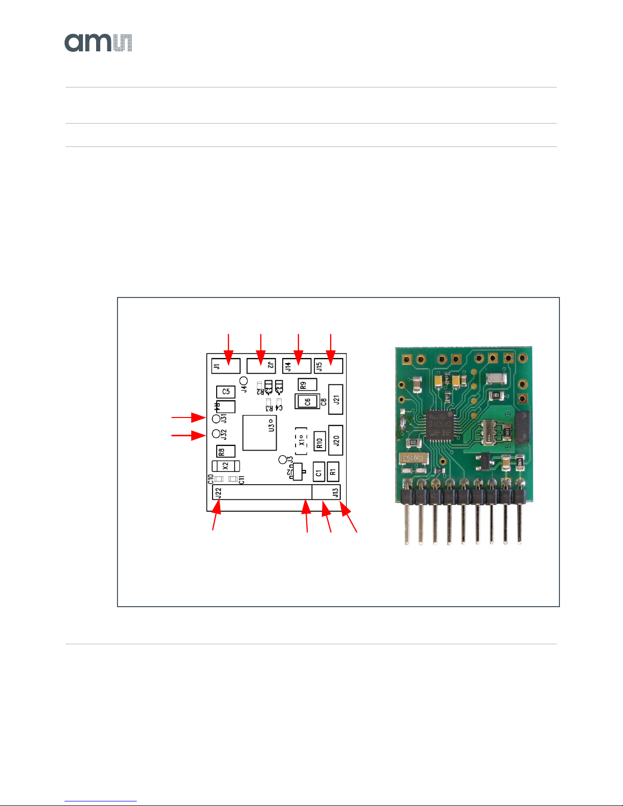
3Hardware Description....................8
3.1 Introduction................................................... 8
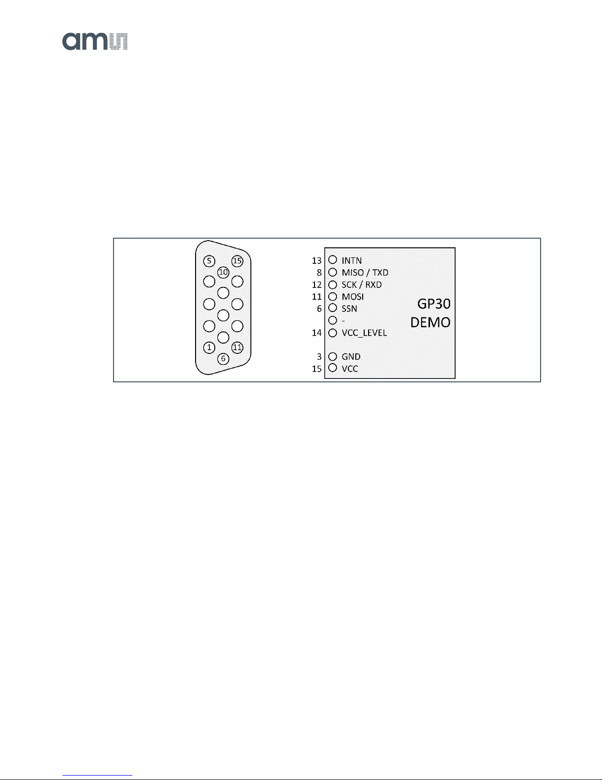
3.2 Communication Interface............................. 8
4Software Description...................10
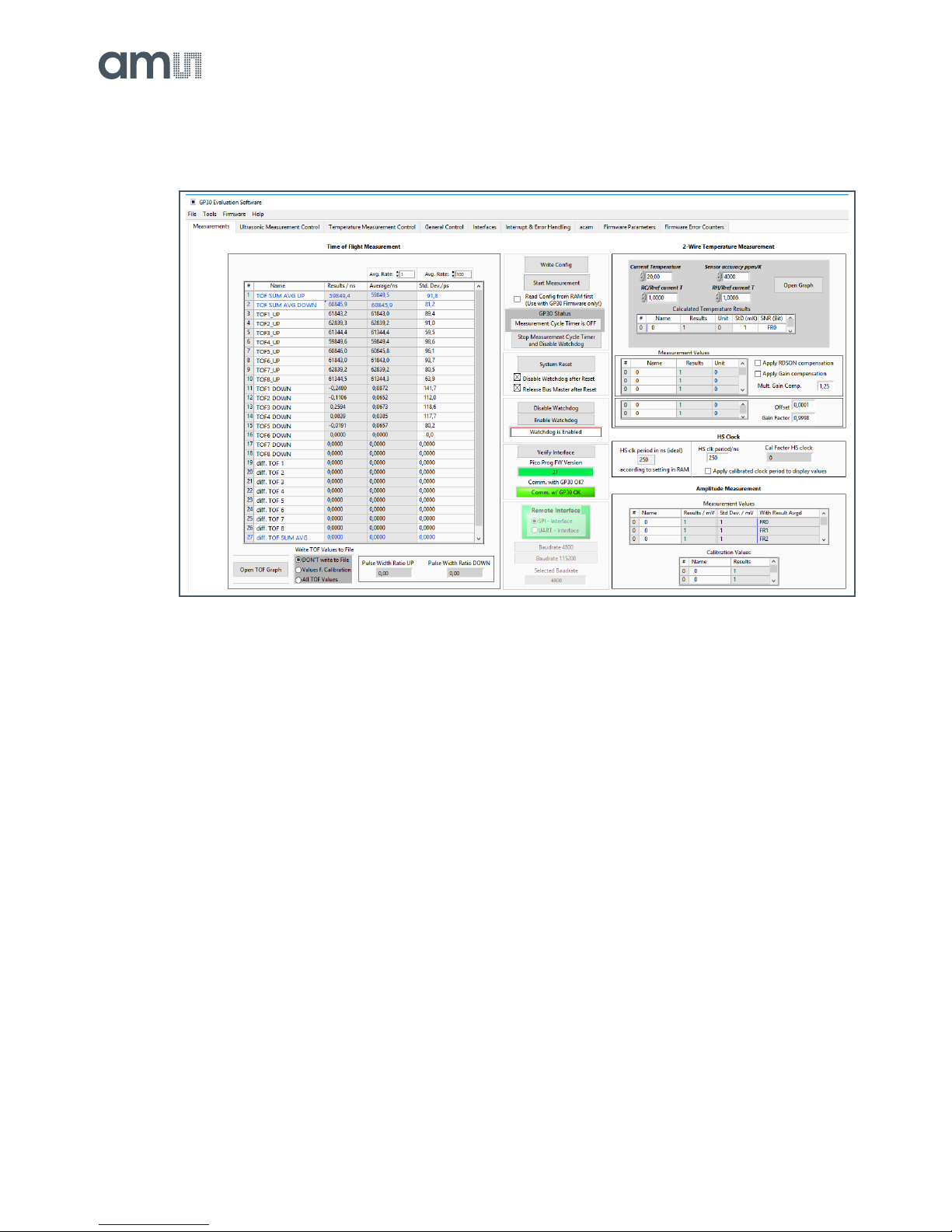
4.1 Measurement .............................................10
4.2 Ultrasonic Measurement Control ...............13
4.3 Temperature Measurement Control........... 14
4.4 General Control.......................................... 15
4.5 Interfaces....................................................16
4.6 Interrupt & Error Handling..........................17
4.7 ams............................................................. 18
4.8 Firmware Parameters and Firmware Error
Counters..................................................... 18
5Software Menu............................. 20
5.1 File.............................................................. 20
5.2 Tools .......................................................... 20
5.3 Firmware.................................................... 22
5.4 Help............................................................ 27
6Schematics, Layers and BOM .... 29
7Reference Modules and
Transducers................................. 32
7.1 Modules...................................................... 32
7.2 Transducers............................................... 36
8Revision Information................... 39
9Legal Information ........................ 40

Document Feedback
TDC-GP30
Introduction
Demo Kit Manual •PUBLIC
UG000292 •v1-00 • 2019-Feb-26
40 │3
1 Introduction
The GP30-DEV-KIT is a platform for a quick and easy start-up and evaluation of the TDC-GP30
ultrasonic flow converter (UFC). It supports the QFN32 package, which offers the functionality need for
standard water and heat meters. The development kit offers user-friendly configuration and extensive
testing of the TDC-GP30, but also the complete assembler environment for programming the device.
For a proper use of the evaluation system, we strongly recommend to refer to the latest TDC-GP30
datasheets.
1.1 Kit Content
Figure 1:
Kit Content
1 PICOPROG V3.0 (Programmer and interface)
2 USB cable (Connects PICOPROG V3.0 to PC)
3 GP30-DEMO MODULE (Based on TDC-GP30 in QFN32 package)
Please download the latest software for the kit from
https://download.ams.com/SPECIALTY-SENSORS/TDC-GP30
1
2
3

Document Feedback
TDC-GP30
Introduction
Demo Kit Manual •PUBLIC
UG000292 •v1-00 • 2019-Feb-26
40 │4
1.2 Ordering Information
Ordering Code
Part Number
Description
GP30-DEV-KIT
220260003
TDC-GP30 Demo Kit for QFN32 version
including PICOPROG and cables
GP30-DEMO-KIT-F01
220260006
TDC-GP30 Demo Kit with firmware for QFN32
version including PICOPROG and cables
GP30-DEMO MODULE
220260002
GP30 demo board for QFN32 version
GP30-DEMO-US-F01
220260005
GP30 demo board with firmware for QFN32
version

Document Feedback
TDC-GP30
Quick Start Guide
Demo Kit Manual •PUBLIC
UG000292 •v1-00 • 2019-Feb-26
40 │5
2 Quick Start Guide
This section describes how to quickly set up the GP30-DEV-KIT, establish basic operation and make
measurements.
2.1 Install the Software
It is crucial to install the software before connecting the evaluation kit to your computer. A default
driver loading of your OS may interfere with correct installation.
●Download the latest zipped software installation package to the desired directory.
●Unzip the package to the desired directory.
●Open “setup.exe” from the unzipped directory.
●Follow the instructions on the screen.
2.2 Install the Hardware
●Make sure software is installed correctly before proceeding with this step!
●Connect your computer with the PICOPROG V3.0 using USB cable.
●Connect PICOPROG V3.0 and the evaluation kit motherboard using the DB15 interfaces
●The green LED on the evaluation kit should be on.
●Connect your spool piece to US_UP and US_DOWN
2.3 Quick Start for Initial Measurements
From the “Start” menu, go to “All Programs” and then to the “ams” directory. Double click the
“GP30_v1_7_0” icon (or newer versions, if available) to begin execution of the evaluation software.
The following screen should appear:

Document Feedback
TDC-GP30
Quick Start Guide
Demo Kit Manual •PUBLIC
UG000292 •v1-00 • 2019-Feb-26
40 │6
Figure 2:
Measurement Page
●Click the “Verify Interface” button to confirm communication between PICOPROG V3.0 and
TDC-GP30 is working. Both fields, “Pico Prog FW version”and “Comm. With GP30 OK?”,
should become green.
●Next, open our configuration GP30Y_config_default_A1.A2.11.03 and download it into the chip,
pressing “Write Config”.
●Connect your spool piece to pins US_UP and US_DOWN.
●Press “Start Measurement” to begin measuring.
At this point, after successful completion of the above steps, a basic operation of the EVA kit should
be possible. The following sections provide a detailed description of the hardware and software for
advanced operation.

Document Feedback
TDC-GP30
Quick Start Guide
Demo Kit Manual •PUBLIC
UG000292 •v1-00 • 2019-Feb-26
40 │7
Figure 3:
PICOPROG Registry
If PICOPROG is not displayed correctly then go to the drivers folder, e.g. C:\Program Files
(x86)\ams\GP30\data\ and install the driver for your operating system manually. In case of an upgrade
of the software to a newer version, please make sure that the software uses the latest driver. For
manual installation open the USB communications window and check the firmware version of the
PICOPROG. It should be version PICOPROG_GP30_v21.hex or higher:
Figure 4:
PICOPROG Manual Installation

Document Feedback
TDC-GP30
Hardware Description
Demo Kit Manual •PUBLIC
UG000292 •v1-00 • 2019-Feb-26
40 │8
3 Hardware Description
3.1 Introduction
The GP30-DEMO MODULE board, shown in Figure 5, is a front-end for a water or heat meters. The
transducers and temperature sensors are directly connected to this board. It comes with a 32.768 kHz
quartz (X2) and a 4 MHz ceramic oscillator (X1). All ports of TDC-GP30 are available. Additional patch
fields allow an easy extension with additional circuits. Those can be amplifiers or analog switches for
operation in gas meter mode.
Figure 5:
GP30-DEMO MODULE
3.2 Communication Interface
The PICOPROG device is a USB-to-SPI converter box that interfaces all UFC evaluation systems.
With version 3.0, the PICOPROG also supports the USB-to-UART conversion of TDC-GP30. The
PICOPROG is registered by the operating system initially as “PICOPROG v3.0 unprogrammed”. As
Piezo
D U
PT1000
C H
GND VCC
INIT
MISO
SCK
MOSI
SSN
-
VCC_LEVEL
Pulse
Interface

Document Feedback
TDC-GP30
Hardware Description
Demo Kit Manual •PUBLIC
UG000292 •v1-00 • 2019-Feb-26
40 │9
soon as the GP30 evaluation software starts, a special firmware is written into the PICOPROG to
handle the SPI or UART communication with the TDC-GP30. The PICOPROG is now listed as
“UNIPRO” in the device manager. For SPI communication only, PICOPROG version 2.0 is sufficient.
Figure 6 shows the connection between the PICOPROG and the GP30 board. The flat connector
includes the power lines and the SPI or UART communication lines. On the demo board the
communication interface is initially selected to SPI (by solder bridge LJ2).
VCC_LEVEL is the voltage feedback for the PICOPROG level shifters.
Figure 6:
SUBD15-Connector

Document Feedback
TDC-GP30
Software Description
Demo Kit Manual •PUBLIC
UG000292 •v1-00 • 2019-Feb-26
40 │10
4 Software Description
4.1 Measurement
When started, the software comes up with the main window, showing the “Measurements” tab.
Figure 7:
Main Window
4.1.1 First Step with Measurement Control Elements
A good first step is to load a working configuration and make measurements in frontend mode (without
using the internal 32-Bit µP). ams provides a sample configuration file named
GP30Y_config_default_A1.A2.11.03 which typically works well with DN20 spool pieces.
Load Configuration File: File menu Open Config choose appropriate configuration file

Document Feedback
TDC-GP30
Software Description
Demo Kit Manual •PUBLIC
UG000292 •v1-00 • 2019-Feb-26
40 │11
1. Press “System Reset” button. Now the PICOPROG FW version field should get green and the
appropriate version should be displayed (20 or higher). Further, “Comm GP30 OK?” should get
green to show that communication with TDC-GP30 works.
2. If watchdog is not disabled by “System Reset”. Button press “Disable Watchdog” button.
3. Press “Write Config” button to download the configuration settings into TDCX-GP30.
4. Press “Start measurement” button. Now the chip starts to measure and the software displays
the results in the table “Time of Flight Measurements”.
The user can now modify the configuration to fit it to his needs. Having done this, the user can store
his own configuration files.
4.1.2 Time of Flight Measurement Results
GP30 stores the first 8 hits of every TOF direction separately and also the sum of all measured hits.
These 9 results are displayed for both directions, as we call them up and down. The evaluation
software additionally calculates the difference between up and down stream, DIFF-TOF. In total, all 27
results are displayed in the “Results” column.
In the “Average” column the user can set the sample size for the averaging (<1000). The software
calculates the rolling average of the results accordingly. In “Std. Dev.” column the standard deviation,
calculated over a variable sample size, is displayed. The number of samples can be chosen (e.g.
100).
The same is done with the amplitude values of the receiving signals and the pulse width ratio between
first hit and start hit. The values for both directions are displayed.
Information
The high speed calibration is by default off. This is more convenient when comparing measurement
data. But when collecting data for calibration it is strongly recommended to have this active
Figure 8:
HS Clock Calibration
A graph to display TOF measurement results opens in a separate window by pressing “TOF Graph”
button

Document Feedback
TDC-GP30
Software Description
Demo Kit Manual •PUBLIC
UG000292 •v1-00 • 2019-Feb-26
40 │12
It is possible to activate up to four plots. Each plot has various selections, e.g. TOF1UP, TOF2UP etc..
Always averaged values are displayed.
Figure 9:
TOF Graph
The measurement data can be exported into text files, either the main values for calibration only, or
the full data.
Figure 10:
Data Export for Calibration
Figure 11:
Data Export Complete

Document Feedback
TDC-GP30
Software Description
Demo Kit Manual •PUBLIC
UG000292 •v1-00 • 2019-Feb-26
40 │13
4.1.3 2-Wire Temperature Measurement Results
A graph to display temperature measurement results opens in a separate window by “Temperature
Graph” button, similar to TOF graph.
Figure 12:
Temperature Measurement Results Graph
4.2 Ultrasonic Measurement Control
In this tab the user makes all settings for an appropriate ultrasonic measurement. They group as
follows:
●Time of Flight Sequence Control
●Time of Flight Hit Control
●Amplitude Measurement Control
●Transducer Interface Options

Document Feedback
TDC-GP30
Software Description
Demo Kit Manual •PUBLIC
UG000292 •v1-00 • 2019-Feb-26
40 │14
Figure 13:
Ultrasonic Measurement Control Tab
The meanings of the various settings are displayed in clear text. For more details about the register
settings please refer to the GP30 manual.
4.3 Temperature Measurement Control
All settings for an appropriate temperature measurement are done in this tab, which are grouped as
follows:
●Sequence Control
●Measurement Control
●Temperature Measurement Cycle Time

Document Feedback
TDC-GP30
Software Description
Demo Kit Manual •PUBLIC
UG000292 •v1-00 • 2019-Feb-26
40 │15
Figure 14:
Temperature Measurement Control Tab
The meanings of the various settings are displayed in clear text. For more details about the register
settings please refer to the GP30 manual.
4.4 General Control
The “General Control”tab covers configuration settings for
●Task sequencing
●High speed clock control
●Voltage measurement
●CPU handling
●Timer settings

Document Feedback
TDC-GP30
Software Description
Demo Kit Manual •PUBLIC
UG000292 •v1-00 • 2019-Feb-26
40 │16
Figure 15:
General Control Tab
The meanings of the various settings are displayed in clear text. For more details about the register
settings please refer to the GP30 manual
4.4.1 Firmware
In case the TDC-GP30 has firmware, setting flag “Enable post processing” turns on the CPU (flow
meter mode). Having this not set, the GP30 runs as front-end in time conversion mode.
4.5 Interfaces
The “Interfaces” tab covers configuration settings for
●Pulse interface including test option
●EEPROM interface
●GPIO control
●UART remote interface.

Document Feedback
TDC-GP30
Software Description
Demo Kit Manual •PUBLIC
UG000292 •v1-00 • 2019-Feb-26
40 │17
Figure 16:
Interfaces Tab
The meanings of the various settings are displayed in clear text. For more details about the register
settings please refer to the GP30 manual.
4.5.1 Pulse Interface
The pulse interface needs an appropriate firmware in the chip. The settings in the evaluation software
only generate an artificial pulse to test the general functionality. The output is not related to any
measurement.
4.5.2 UART
The UART is not supported in this software version.
4.6 Interrupt & Error Handling
On this tab error indicators and interrupt sources for remote interface can be selected.

Document Feedback
TDC-GP30
Software Description
Demo Kit Manual •PUBLIC
UG000292 •v1-00 • 2019-Feb-26
40 │18
Figure 17:
Interrupt and Error Handling
The meanings of the various settings are displayed in clear text. For more details about the register
settings please refer to the GP30 manual.
4.7 ams
On this tab, named acam, specific parameters are displayed, but for ams internal use and analysis
only.
4.8 Firmware Parameters and Firmware Error Counters
Those two tabs display and allow editing of parameters related to the ams flow firmware. They are of
use only for TDC-GP30-F01. For details please refer to the datasheet TDC-GP30 Vol.4 Firmware
Overview.

Document Feedback
TDC-GP30
Software Description
Demo Kit Manual •PUBLIC
UG000292 •v1-00 • 2019-Feb-26
40 │19
Figure 18:
Firmware Parameters Tab
Figure 19:
Firmware Error Counters

Document Feedback
TDC-GP30
Software Menu
Demo Kit Manual •PUBLIC
UG000292 •v1-00 • 2019-Feb-26
40 │20
5 Software Menu
Beside main window, the software menu allows the opening of other windows. There are some menu
items which are redundant to available buttons of main window.
5.1 File
●Open Config
This dialog box allows the path selection of a configuration file, covering the register settings,
necessary for a proper configuration of the GP30. After opening this file, the control settings are
updated in the GUI.
●Save Config
This menu item allows the saving of the current GUI control settings into a configuration file
●Close
Close all open windows of the GP30 Evaluation software.
5.2 Tools
●Run Measurement
Same function as “Start/Stop Measurement” button in “Measurement” tab of main window.
●TOF Graph
Same function as “Open TOF Graph” button in “Measurement” tab of main window.
●Temperature Graph
Same function as “Open Graph” button for temperature measurement in “Measurement” tab of main
window.
Table of contents
Other AMS Motherboard manuals

AMS
AMS AS5 47 Series User manual

AMS
AMS TSL2521 User manual

AMS
AMS AS3956 User manual

AMS
AMS AS5048 Eval-Kit Manual

AMS
AMS TMD2620-DB User manual

AMS
AMS AS703X_EVALKIT_BT User manual

AMS
AMS AS3933 Operating and installation instructions

AMS
AMS AN5000 Series Installation and operating instructions

AMS
AMS AS7058 User manual

AMS
AMS AS3935 User manual