Anacortes Yacht Charters Meg Ann lll 1998 5788 Bayliner User manual

0
Operating Manual for
Meg Ann lll
1998 5788 Bayliner

1
Contents
OPERATIONS MANUAL ...............................................................................................................................................2
A. MAIN ENGINE CHECKOUT (pre-start) ...................................................................................................................3
A. 120 @ 2 4 0 VOLT SYSTEM: power sources and discussion ....................................................................................7
B. SHORE POWER: GENERAL .....................................................................................................................................9
C. GENERATOR STARTING AND USE .......................................................................................................................10
D. INVERTER – 4000-Watt 110v Power ........................................................................................................................10
E. ELECTRIC WATER HEATER.................................................................................................................................... 11
F. 24 VOLT SYSTEM ..................................................................................................................................................... 11
G. BATTERY SWITCHES ..............................................................................................................................................12
MARINE HEADS AND HOLDING TANK .................................................................................................................. 12
THE VACU-FLUSH HEADS ..........................................................................................................................................13
TOILET OPERATION .....................................................................................................................................................13
A. STOVE TOP ................................................................................................................................................................16
B. MICROWAVE .............................................................................................................................................................16
REFRIGERATORS, FREEZER AND ICE MAKERS ....................................................................................................16
ELECTRONICS: NAVIGATION EQUIPMENT, RADIOS & RADAR .........................................................................17
SETTING ANCHOR ........................................................................................................................................................21
ANCHORING ..................................................................................................................................................................21
CHECKLISTS & MANEUVERING SUGGESTIONS SHORE LINES ........................................................................22
WEIGHING ANCHOR ....................................................................................................................................................24
HOISTING DINGHY ON AND OFF MEG ANN lll ......................................................................................................24
OFF-LOADING DINGHY .............................................................................................................................................. 24
RE-LOADING DINGHY TO THE FLYBRIDGE ...........................................................................................................26
Loading .............................................................................................................................................................................26
OPERATING THE DINGHY ...........................................................................................................................................27
SALON COFFE TABLE ADJUSTMENT .......................................................................................................................27
STACKED WASHER/DRYER ........................................................................................................................................28
PROBLEM SOLVING .....................................................................................................................................................32

2
OPERATIONS MANUAL
We hope you have a very enjoyable and safe trip aboard Happy Ours and at your
destinations. This manual is provided to assist you in operating the boat and all the
systems aboard. Please take time to review this manual thoroughly. Be sure
to contact your Checkout Captain to verify information and/or ask any
questions.
The ultimate responsibility for the safety of crew and vessel is with the person
who charters the boat. The chartering Captain has represented that his/her experience,
judgment, and skills are adequate to overcome any errors and/or omissions in this manual
and checkout procedures.
This manual provides information necessary for an experienced boater to operate the
systems and equipment on Megann lll. This is not a training manual and assumes that
the reader has sufficient experience with similar yachts and systems.
Safety is a top priority. All procedures should be clearly understood before proceeding.
Safety cannot be completely managed by procedures alone and requires experience and
common sense to be achieved.
This manual does not include navigational, weather assessment, or boat
handling skill instructions.
As the Captain, you are responsible for the safety of all crew members and the
yacht. It is the Captain’s responsibility to understand all instruction and information
provided in this manual. If there are any questions about this manual or if any scenario
that this manual does not cover, please call Anacortes Yacht Charters at 1- 800-
233-3004, for assistance.
IMPORTANT POINTS:
Safety is the most important item in all of the following information and safety
considerations will be emphasized. Plan ahead and review procedures to prevent
accidents. Make sure your crew is prepared to assist as needed by training them
beforehand. Inform all onboard how better to assist you and what is expected from them.
This is especially important when readying the ship for voyage, for docking, and for
anchoring. Almost anything done without preparation can be high risk for accidents, so
take your time, train your crew before they have to perform, and let everyone enjoy the
fun!

3
Please read this complete manual thoroughly and ask AYC about anything that
is not clear or that may be missing. Taking the time to read this manual completely
will save you time, money, and risk of injury when arrive on holiday.
1. PRE-START CHECK LIST
Before you operate the vessel for the day, do an inspection of the mechanical systems and
the engine room. Any problem is much easier and safer to fix while securely tied up at
dock, or at anchor, than it is while adrift.
A. MAIN ENGINE CHECKOUT (pre-start)
1) With a flashlight, enter engine room from the aft deck. The entry is located under
the stair to the bridge hatch on the aft deck. Lift the stairs to gain access to the room.
Engine room light is located on the left sidewall as you enter.
CAUTION: WHEN REPLACING HATCH DO NOT LET IT SLAM SHUT.
2) Check oil level in main engines once weekly. Dipsticks are down low near center of
engines facing centerline of boat. Oil level should be between the full and add marks.
If below the add mark add oil until it gets between the full and add mark. In between
weekly oil quantity checks - check below engine for oil leakage. If substantial oil
leakage is found check quantity.
3) Check fresh water coolant (orange) level in inboard radiator caps on the engines.
They are located inboard of each engine. When cold only a small amount is visible
above the screen, they will have much more in them when engine is warm and the
coolant expands.
4) Check for water in the bilges. There should be no more than 1 inch or less in the aft
portion of the aft lazarette area (or under the bedroom hallway). There should not be
any in the engine room proper, if so manually turn on bilge pump to pump out).
Check general condition of all belts, hoses and fuel lines.
5) Verify through-hull valves for each engine and the generator are open.
6) Check sea strainers inboard of each engine for obvious obstructions like seaweed
or plastic. There are sea strainers for the engines (2), water maker (1), and
generator (1).
To Clean Sea Strainers: Close thru hull valve for sea strainer raw water intake, and
disassemble sea strainer and clean basket. Re-assemble sea strainer, open thru hull
and make sure there are no leaks.

4
7) Inspect the Racor fuel filters and make sure they are clear and do not have water or
debris accumulated in the bottom by shining the flashlight through the filter housing
towards yourself. There are 2 filters per engine. If water is present, it may be drained
out through the valve on the bottom of the filter housing. BE SURE TO HAVE A
CONTAINER READYAND PLACE AN ABSORBENT PAD UNDERNEATH TO
CATCH ANY WATER AND FUEL! Clean up any spilled fuel immediately. Make sure the
valve is closed and not dripping.
8) Check transmission fluid levels weekly. Dip sticks are on the inboard side of each
transmission. Re-insert dipsticks and make sure they are firmly in place.
9) Look for anything else that looks out of place, loose, disconnected, or broken. There
should not be any fluids under the engines and the drip pads should be mostly clean. If
you notice any significant fluid, identify the source and cleanup then notify AYC.
STARTING and STOPPING MAIN ENGINES
After your engine room check, you are ready to start main engines.
NOTE: The KEYs are used to turn on the starter motors and start the engines and
also, to stop the engines. Start the engines by turning each key clockwise. Stop the
engines by turning key counterclockwise.
Note: Diesel engines run by compression of the fuel not by a spark plug. When you
engage the ignition switches, you are engaging the starter motor and are turning on a fuel
valve which allows the engine be started and to run. They will continue to run until fuel
is shut off. When the ignition switches are turned off, they release a magneto (magnetic
switch) which closes off the fuel supply which in turn kills the engines.
If engines have been off for over 8 hours, make sure they run for at least 5 minutes and
that the temperature gauges show at least 140 before going over 1000 RPM. Running
underway with cold engines can more than double fuel consumption and can cause
engine failure.
Make sure engine power levers are in neutral before
starting. Note: Engines will not start while if power levers
are in gear!
Turn on ignition key(s).
ALARMS:
Loud buzzing alarms will sound when the keys are turned on: this is normal, these
alarms indicate that the alarm system is working. They are monitoring low oil
pressure at this point. You should hear these whenever the key is turned on and for
the first 5 seconds or so when the engines first start running.

5
They will also sound when the engines are running if coolant temperature exceeds
a safe operating temperature, and the alarms receive signals from one of several
sensors at different locations on the engine.
If you hear these alarms when the engine is running beyond the first several seconds
or underway, there is probably an emergency situation and the engines should be
dropped to an idle for 10 to 15 seconds while you observe the dash gauges for oil
pressure and temperature condition. If you observe low oil pressure, shut down the
affected engine immediately.
If you observe excessive temperature, first allow the engines to idle for around 10
seconds, if the alarm stops or if the temperature is dropping, continue running until
the alarm stops. A slow drop usually indicates a blockage of the water intake or if
the alarms occur only at higher cruising speed it could also indicate an excessive
load on the propeller.
If, however, no temperature progress is observed, you need to shut down the engine
as the alarm could be coming from one of several engine conditions, such as
failure of a water pump or belt, failed impellor in the pump, an extremely low oil
condition or other problems.
If this occurs you need investigate the possible conditions and call AYC and or the
Owner for instructions, prior to restarting the engine.

6
START ENGINES:
1) Turn ignition key fully to the right engine should start in 5 seconds or less.
Repeat for second engine.
2) Let the engines warm up.
3) Voltmeter gauge will read 26-28 volts.
4) Oil pressure will read around 50 psi or above for cold engines. Warm engines will
read in the 30‘s when idling but should never be at zero for a running engine.
5) Engine temperature should rise to operating temperature of 160-180 degrees in
about 5 minutes at idle. Keep engine RPM below 1000 until temperature is at least
140.
EMERGENCY STARTING: If starting batteries are run down and will not start
engines or generator use the emergency battery parallel switch in the pilothouse helm to
connect the start batteries to the house batteries giving them a boost and start the
generator. This switch is adjacent the start switches on the left.
ENGINE SLOWDOWN AND SHUTDOWN
1) VERY IMPORTANT: When running at cruising speeds, avoid suddenly
dropping engine speed to idle. Gradually reduce speed over a minute
or more. Rapid changes in RPM can cause rapid temperature changes in
the engine and exhaust system which can cause engine or exhaust heat stress
cracks and/or breakdowns.
Then let engines idle for at least 5 minutes to cool down the turbos and fully
lubricate the engine. Do not shut the main engines down immediately after
running at cruising speeds. Cooling down will also help to avoid coolant boilover
and vapor locks in the fuel line due to overheating.
2) To turn off each engine, turn off the respective key

7
ELECTRICALSYSTEMS:
A. 120 @ 240 VOLT SYSTEM: power sources and discussion
120 Volt electricity is used to run TV/VCRs, Convenience Outlets
Microwave and one of the two 24-volt Battery Chargers, etc.
The 240-volt circuits run the Cooktop/ Oven Washer/ Dryer /
and the other of the two 24-volt Battery Chargers
• The 120-volt system breakers are in the cabinet in the pilot house helm on the
Starboard side aft of the pilothouse door. The 110-volt breakers are located at the
base of the panel, directly below the 240-volt breakers.
• Breaker switches for shore power or Ship (generator power) are located in this
panel in the center just under the Voltage Meter. The breaker switch is set up
with a slide cover so that only one source can be used at a time.
• 240-volt power can be obtained from two sources.
1. Shore power 50-amp plug
2. Shore power from two 30amp plugs using the Y adapter (must be 120/240
volts shore power with each 30 amps sourced from a different leg of the 240V
service)
3. generator
120-volt power can be obtained from three sources.
1. Leg one of a 240 service (50 AMP Shore power)
2. Leg two of the 240-volt service (50 AMP Shore power)
3. Both legs as single source 120 volts when the 50
amp to 30-amp single adapter is used.

8
4. Both legs as separate 120-volt sources when the
2@30 amp to 50 amp “Y” adapter is used
5. Inverter (feeds both of the two120v panel areas) but none of the 240 panel
area is available
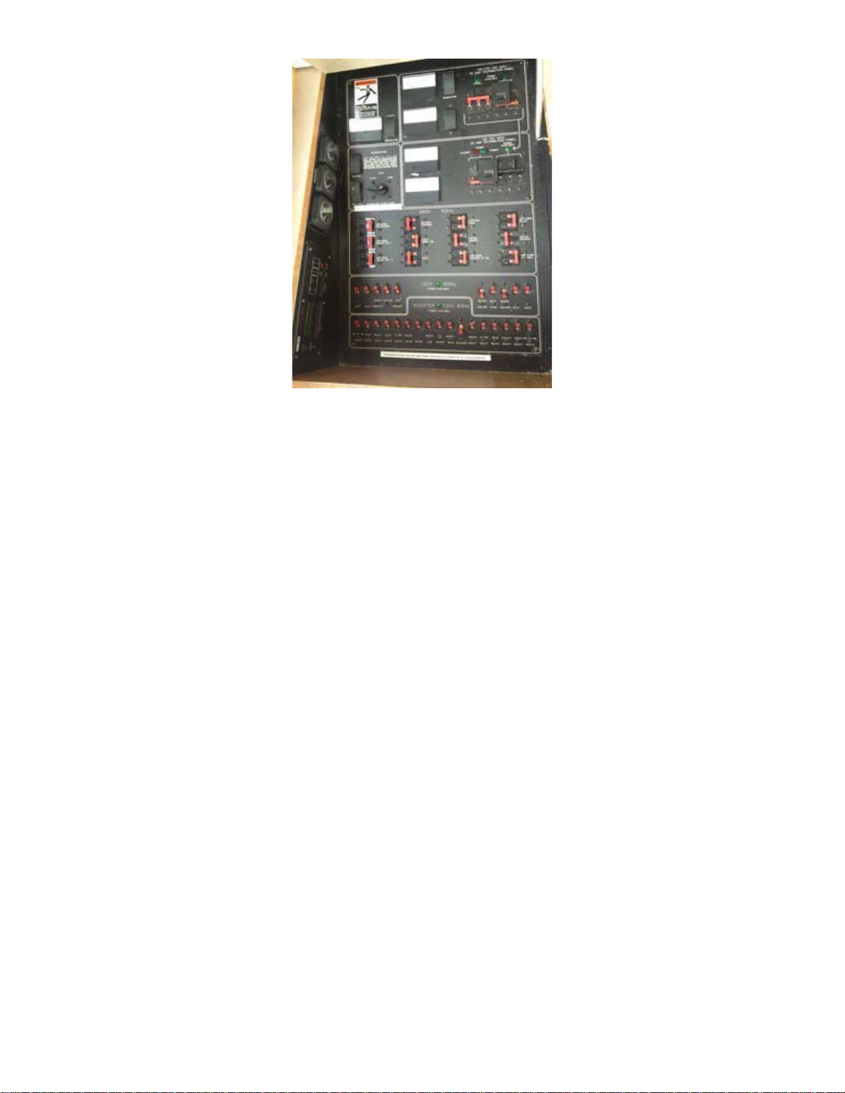
There are 2 sections of the 120-volt panel area, the upper section draws power
from the second leg of the 240 current and the lower section from the other.
Note: When using the Y- 2@30 amp to 50-amp adapter (when no 240/120 50 amp
shore power is available) each 30-amp leg must be from a different leg of a 240volt
dock wiring system which will give you a 240-volt source. When the single 30
amp to 50-amp adapter is used both sections of the 120-volt panel are active but
with only 30 amps.
NOTE: When 240-volt power is supplied from shore power from a 50 amp
connection or 2@30 amps feeds as described above, or from the generator, the
remove trace inverter panel on the left of theAC Panel sidewall will indicate good
power source when the two green indicator light are on, one solid and one
blinking. Also, the inverter orange light to the left will come on for a few seconds
and then automatically it will switch to the right top under “bulk” this indicates
that the inverter charging system is active. When the inverter sees full charge the
light will drop to the lower “float” position and turn green. The two-green light
should always be on when a power source is supplied by one 50-amp cord
including when using adapters
If a red error light appears or if only the orange inverter light is still on you are not
getting an AC power source nor is the charging system active, and batteries will
run down. Check for the proper position of the panel breakers, the shore power
connection and or pedestal breaker on the dock and be sure the digital readout
setting is on “Set Inverter, and the source indicator (small underline indication) is
set to float. This needs attention and resolution before moving on to other activities.
Hopefully this will not occur but if so refer to the race (Zantrax) manual overhead
in the pilot house or the abbreviated copy on the actual inverter in the engine room.
Occasionally the remote inverter panel is illegible and you will need to go to the
main inverter control panel (identical appearance) on the face of the inverter in the
engine room to make settings if needed.
NOTE: when operating on inverter power only you should see only the orange
inverter light on. If there are no lights on, there is no AC power available on the
boat.
IF ADJUSTING THE INVERTER SETTINGS IS REQUIRED, CALLAYC OR
THE OWNER FOR TROUBLE SHOOTING HELP!

9
B. SHORE POWER: GENERAL
Important!! Make sure you read this section and understand it completely!
Special Considerations: Care should be taken not to exceed the shore power available.
This vessel’s potential to consume electricity will exceed the dock’s capacity to provide it
unless you are connected to 50 Amp power. (Very rare for transient moorage)
Note that most shore power you connect to will be 120V 20, 30 or 50Amp. If 50 Amp
power is not available there is 30 AMP cable in the engine room that connects to the 30
Amp outlet in the cockpit next to the 50 Amp cable.
The 100’50-amp shore power cord is on an electrically operated cord (Glendenning reel
system) located on the cockpit side of the transom and can be accessed from below the
teak half table. Remove the chrome cover for the electric cord the move 3 position switch
to the “out” position. The electric cord will begin to reel out onto into the cockpit. Once
enough cord has been reeled out to allow it to be connected to the shore power receptacle
turn the reel switch to the stop position.
To stow the electric cord simply reverse the operation using the retract side on the reel
switch. Once fully retracted the reel will automatically stop but you need to return the
switch to the center “off” position when done.
Be extra careful to be sure the chrome lid does not drop onto the cord while retrieving as
it will jam and can damage the system. Feed the cord into the opening rather than letting
the cord pull itself in. NEVER ALLOW THE PUG END OF THE CHORD TO FALL
INTO THE SALTWATER! This will cause corrosion and future failure. If it should
accidently fall in the saltwater, flush with fresh water immediately before stowing.
NOTE: You cannot use all 120 circuits and electrical items with only one 30 amp
source. (watts = volts x amps, IE: 30 amps at 110 volts = 3300 watts) It may pop the
shore power circuit breaker. Check the ammeter on the power panel to see how much
power you are using or simply do a quick calculation of the loads you want to access.
You may have to alternate between electric cook-top, water heater, and battery chargers
in order to avoid popping the shore power breaker. Priority should always be given to
the inverter which will charge all the batteries.

10
C. GENERATOR STARTING AND USE
When shore power is unavailable, the generator can fully power the boat. It is a good idea to
run the generator every day that you have not been connected to shore power to recharge all
the batteries. Monitor the battery voltage levels to determine how long to run the generator.
The generator may be operated while underway or at anchor. When using while anchoring be
Sure that you are not over eel grass or other debris which might get drawn into the intake and
stop
water flow during operation. Monitor this process frequently during this use.
Access the main Power Panel:
1. To start generator simply press the start button in the AC electric cabinet. Listen for the
generator engine noise.
2. Next, Move the 240-volt breaker slide over the shore power breaker and engage the
Generator 240-volt breaker (left side of the primary power source diagram). This will put the
generator online.
3. Never run generator for less than 30 minutes from a cold start.
4. To turn off generator press the stop button. This will automatically shut down the
generator.
D. INVERTER – 4000-Watt 110v Power
NOTE: The inverter system is setup to be totally automatic and should not need any
changes to the settings. 120-volt power can be provided by the inverter which uses 24
volt battery power to make 120-volt AC current. 120-volt power is very limited with the
inverter because it comes from a limited source. You cannot run high use devices like
space heaters, hair dryers, waffle irons, at the same time or for any combined length of
time. It will drain the batteries to the point of inverter shutdown.
The inverter’s best use is to provide low wattage, or intermittent 120-volt power during an
evening to save the generator from constant short start-ups and shut downs.
When the boat is on shore power or has the generator running, the inverter becomes a battery
charger for the house battery banks.
The remote switch and indicator panel for the inverter is located to the left of the electrical
panel console. NO SETTINGS SHOULD BE CHANGED ON THE INVERTER
CONTROL PANEL.
To operate the inverter:
1. Turn on the breaker on the 120-volt panel.
2. The inverter is operated by the remote panel to the top right of the electrical panel. (or on
the face of the inverter n the engine room)
The inverter can be in standby or off for 120-volt power. The charger can be
selected on or off. Typically, the inverter is off and the charger is on. The proper
setting is “SRC” (search) and the inverter will automatically change from
inverting to shore power/ generator power when available.
3. The inverter will power the 120v AC outlets, ice maker, refrigerator and the
microwave etc. (see AC panel)

11
4. Be careful on entering the engine room not to turn inverter switch off (located
near the bottom of the DC Battery switch panel and located where it can be hit
accidentally with your leg.
E. ELECTRIC WATER HEATER
The electric water heater runs off of the 120-volt system. The circuit breaker is on the
120-volt panel. VERY IMPORTANT: Do not use the electric water heater if the water
tanks are very low or if they run dry. The electric element may burn up if the tank has no
water.
Turn off when conserving battery power (inverter mode when at anchor or no AC
sources active). The water heater is also heated by the engines.
F. 24 VOLT SYSTEM
The 24-volt system runs the electrical systems necessary to operate the vessel.
Bilge pumps, water pumps, electric toilets, navigation lights, house lights,
electronics, etc. are 24-volt systems.
Overboard sewage switch
24VoltBreakersWindlass
BowThrusteronly
24 Volt Battery power panel
DC PANEL OPERATION
• Turn on all 24V breakers.

12
For safety, Windlass Control breaker should be OFF except when using the windlass. Holding
Tank Pump and Raw Water Wash Down Pump should be OFF.
NOTE: all bilge pump breakers should be ON and switches should be set to
automatic all the time.
The 24-volt circuit breakers are located on the top of the DC panel. Only use the light you
need. There are sufficient lights and other 24-volt devices to drain the house batteries of
power if they were all left on overnight.
G. BATTERY SWITCHES
The battery switches are located in the engine room on the aft bulkhead immediately to the
left as you enter the engine room. These are normally left in the “On” position.
24‐voltpanel
12‐voltpanel
12‐voltbreaker
MARINE HEADS AND HOLDING TANK
This vessel has two heads, each with an electric toilet. It has one holding tank with a capacity
indicator in the 24-volt cabinet.

13
THE VACU-FLUSH HEADS
These premium heads are easy to use, odor free, and very reliable. They work with two
separate vacuum pumps and vacuum accumulator tanks. A vacuum is maintained in the tank
until the head is used, when the waste matter in the bowl is sucked out of the head by the
vacuum, then it is pumped through the system by the head pump, which then also pumps up
a vacuum again. Note that it is this rush of the head’s contents caused by the accumulated
vacuum that is important to the head’s operation! This sudden rush causes any solid material
in the waste stream to be shattered as it passes through the specially- shaped orifice in the
bottom of the head. For this reason, proper head operation requires that the head pedal not
be held down for long periods of time.
The head uses about a half pint of fresh water from the ship’s supply with each flush. The
head is operated by a pedal to the left of the head base (as you face the head), and operation
is as follows:
TOILET OPERATION
1) Before using the head if the waste will be solid, lift the pedal to add water to the bowl;
2) Use the head;
3) Step on the pedal just long enough to hear the “whoosh” as the head is evacuated and a
small amount of water rinses the bowl - - - about five seconds!
4) Releasing the pedal, if you wish to flush again, wait at least twenty seconds or so
(until you hear the head pump stop) before flushing again.
As the pedal is released, the ball-valve at the bottom of the head seals it so that the vacuum
can be pumped up, the pump will then stop, and the head is again ready for use. If the head
pump runs often or steadily between flushes, it is likely that the seal at the
bottom of the bowl did not seal completely: you can tell if there is no water in the bowl. The
solution is usually simple: Flush the head again and make sure the pedal comes all the way
up when you remove your foot from it; then make sure the water doesn’t leak out.
Only things which were eaten or drunk, or the toilet paper supplied with the boat, should be
put in the heads! Facial tissues, tampons, and other foreign matter will clog the system. If
these heads are used properly, they are quite reliable. Failures are virtually always due to

14
mis-use! When it comes to tissue, usually “four squares are enough!”
If the toilet bowl becomes clogged from too much paper try one again to flush but DO NOT
HOLD THE PEDAL DOWN CONTINUOUSLY!! The toilet bowl fills with water
whenever the pedal is depressed. If there is a clog, IE the waste will not suck through the
small opening, you will have to follow the procedure as follows. IF YOU HOLD THE
PEDAL CONTINUOUSLY and let the bowl fill with water you cannot work on the issue
any longer without the water spilling onto the floor.
If there is a clog that won’t suck through after one additional attempt, find a small object
such as a coat hanger wire or kabob skewer and use it to gently push the obstruction through
the small opening (visible only when the pedal is depressed and the white cover is retracted)
at the very bottom (in the black plastic). However, you need to act quickly and cannot have
the bowl already full if this is to be attempted.
If the obstruction does not suck through quickly stop and release the pedal to cut off the
water flow. If the obstruction is other than the permitted waste and paper type do not push it
through!! The problems magnify if the improper waste passes through and Jams the system
further along in the pumps!
Procedure:
a. Turn off the main vessel water pressure and toilet pumps switches on the DC Panel.
b. Open faucets and tub cold water valves and let the water pressure in the boat drop
completely and no more water comes out the faucets etc.
c. Close these faucets and tub valves.
d. You now can depress the foot pedal without more water entering the bowl and this
gives you time to work the problem without chance of spillover.
If the obstruction is from excess permitted (supplied) toilet paper you can continue to try and
gently push it through while hold the pedal down and exposing the bottom (black area) of the
bowl below the white rotating lower bowl door but if the clog is from improper waste it must
be removed (if possible, without damage to the plastic components, Try making a small hook
from a straightened coat hanger and pull it up into the bowl and remove it. If this cannot be
done. You will need to cease use of the toilet and seek help from the Owner or AYC. If this
is necessary you can turn on the water pressure and other switches on the DC panel, but do
not depress the foot pedal again until this problem has been resolved.
If the clog was from the AYC provided toilet paper, it will dissolve when wet and the clog
might release later (if you have not already filled the bowl to the overflow point) If you have
purchased other paper, waiting will not help.
In US. Waters, the Coast Guard Rules require that the valves be “secured" in the holding tank
position to assure that all effluent will be kept aboard in the tank. However, the Coast Guard
has allowed adequate warning and electronic disabling as on the Ques Sara to satisfy this
requirement. Therefore, the Y Valve (to the right of the holding tank below the
companionway floor) should be left to the overboard position.
The holding tank is below the companionway (hallway, Sole) floor below the removal
carpeted floor panels. These panels also give access to the pumping system, the washdown

15
pump and two bilge pumps. MEG ANN lll is equipped with holding tank indicators on the DC
Panel.
A deck plate on the starboard side deck allow pumping of the holding tank at a shore-side
waste pump out station.A mobile service is available through the marinas at Friday Harbor
and Roche Harbor.
To pump the tanks overboard (Only in Canadian Water, pursuant to regulations). First make
sure, the thru-hull valve located under the companion way is in the open position. To operate
the pump the Breaker must be on in the DC panel. There is a macerator pump switch located
in the upper left of the DC Panel. It has a safety switch on that must be pulled down prior to
depressing the actual switch. It must be held down for the pumping to proceed.
Turn “on” the “Waste Pump” breaker in the DC panel by the salon-pilothouse steps. Operate
the switch on the upper left side of the DC panel until the tank is empty. Do not let the pump
run dry: It will be damaged! The effluent passes through at the hose and pipe aft to the pump
and thru-hull valve.
When you are done, turn off the pilothouse DC panel “Waste Pump” breaker and close the
thru-hull.
IMPORTANT: You must be mindful of the extent of your crew’s use of the holding tank. Do
not rely only on the holding tank warning light located on the DC panel.
NEVER allow the holding tank to overfill. It is possible to break a hose, clog the overflow
vent, or burst the tank if it is used when it is full. The result is an indescribable unpleasant
catastrophe for the whole crew and a costly repair bill.

16
As note before, pumping out the holding tank is done one of two ways. There is a deck
pump out port on the starboard side (at about the mid salon) for use with marina pump out
stations. Also, the boat is equipped with a macerator overboard pump. The contents of the
holding tank can be pumped overboard with the macerator pump in appropriate areas.
(NOTE: Anchorages and harbors are never legal/appropriate places.)
TUB, SHOWER AND SUMPS
The tub shower and single shower each have a sump pump that is activated by a float
switch. This requires the 24-volt circuit breaker to be on. If the shower is used without the
circuit breaker, the shower water will end up in the bilges and be pumped out by the bilge
pumps. Shower water in the bilges can get smelly, so please make sure the sump pumps are
used.
Each head has an exhaust fan. Do not leave running for long periods of time to avoid
excessive battery drains if you are not using shore power.
GALLEY
A. STOVE TOP
The stove top is powered by the breaker on the 240-volt panel. You must have at least 30
amp shore power and limited other 110v use, or the generator running to operate the stove
top.
B. MICROWAVE
The microwave is connected to the power inverter.
Do not use the microwave for extended cooking while on power inverter. Any cooking more
than 15 minutes should be done while connected to shore power or running generator,
otherwise, you may run down the inverter batteries.
Coffee maker, toaster, and other electrical appliances may be plugged into the power outlets
in the galley that are powered by the battery inverter. Use care when using multiple
devices simultaneously as the breaker may pop or inverter power may turn off due to over
loading the circuit. THESEAPPLIANCES ARE STOWED BELOW THE COUNTER
ACCESS PANEL TO THE LEFT OF THE COOKTOP
Galley Crew Note:
The sink does not have a garbage disposal. Do not put coffee grounds down the drain. Doing
so, will clog the overboard drain. Note the sink discharges directly into the water. All waste
should go into Trash bags. Or in garbage bags to be disposed of at marinas.
REFRIGERATORS, FREEZER AND ICE MAKERS
Galley: This refrigerator freezer is 110 volts only and runs off the shore power, generator,
or inverter powered by the house batteries. The refrigerator will take 8-12 hours to fully
cool down when first turned on. However, it is normally on prior to the commencement
of charter. If on the hook and using inverter power it is standard procedure to turn off the

17
inverter prior to going to sleep to protect the batteries. Or turn off the heavy loads (refrig,
CB, Water Heater, Battery charges, and ice maker. The refrigerator/freezer will remain cold during the
night. Remember to turn on the
refrigerators or the inverter in the morning or the generator (necessary for hot water for
showers)
Flybridge: There is an under counter style mini fridge / icemaker under the sink counter.
There also is a box freezer located to the right of the counter. The mini fridge is controlled
by a breaker in the AC Panel “refrigerator CB” next to the refrigerator breaker. The
freezer is controlled by plugging it into an extension cord between the freezer and the
console.
Main Salon: An under counter Ice maker is located near the bar sink.
ELECTRONICS: NAVIGATION EQUIPMENT, RADIOS & RADAR
Overview
The boat is equipped with extensive electronic equipment, including VHF radios, radar, Furuno
MDF,depth sounder, and an autopilot.
The DC power supply for this equipment is controlled by a single electronics master circuit
breaker at the bottom of the DC power panel. Each unit or group has its own power switch
in the same location.
This manual does not attempt to provide operating instructions for any of the electronic
equipment. Instead, you are referred to the equipment’s own manuals kept in the pilothouse
overhead cabinet
VHF Radios
The VHF radios’controls are at both helm stations, in the salon and on the flying bridge. The
radios are designed for easy access to Channel 16, which is the hailing and emergency channel in
the Northwest. Other buttons allow you to select different channels, weather channels, high and
low power, and US/International operation. Your checkout skipper and/or the radio’s own
instructions will quickly familiarize you with basic operation.
Be sure to re-check the squelch each time you turn it on.
PILOT HOUSE EQUIPMENT LAYOUT
The MEG ANN lll is equipped radar that can be used, combined with the electronic chart
units, for operation in restricted visibility, with the radar primarily serving as a device for
collision avoidance while the chart unit provides position.
Proper and safe use of a ship’s radar requires lots of practice and careful study. While you are
using the boat, you can have the radar on as much as you like to get used to the way it displays
images, but for detailed operating instructions we refer you to the radar’s own complete manual
and details bottom of next page.
Note that charterer’s insurance DOES NOT PERMIT OPERATION OF THE VESSEL IN

18
RESTRICTED VISIBILITY. You should confine your use of the radar to familiarization and
training only in weather with good visibility.
NOTE: RADAR IS NOTA SUBSTITUTE FOR VISIBILITYAND CANNOT
DISPLAYALL OBSTACLES OR DANGERS. (Example: it is impossible for radar to see
the cable between a tug and its tow, or realize that that is the situation without visible
clues.) Only use radar for supplemental information or when seeking shelter if caught in
fog.
REMEMBER: THE ELECTRONIC CHARTING SYSTEM IS NOT A SUBSTITUTE FOR
CAREFUL STUDY OF TRADITIONAL PAPER CHARTS. You are required by maritime law
to use your paper charts for navigation information, especially since electronic chart technology
does not always permit full cartographic details to show, especially underwater hazards. The
electronic charts are for convenience only!
Note: Northwest waters are rocky and depths change rapidly. You should be especially careful to
study your charts, and then check them often whenever running in lesser depths, so that you
don’t hit a rock! Just as our islands “pop up” to heights of 50, 100, or even thousands of feet in a
very small distance, so do rocky obstacles underwater!Also remember the 15ft tidal swing in
depth, rocks that may have been 16 ft under water may at some point in time be merely 3 ft
under the surface. MEG ANN lll draws 5.5ft.
NOBELTEC NAVIGATION SYSTEM:
The first of the two Navigation systems is Nobeltec software installed on a PC located left of the
wheel in the pilothouse. Attached to the computer are USB connections for the GPS receiver and
a dongle for the wireless mouse. The PC is connected to the screen to left of the pilothouse
equipment displays.
To operate this system, you need to start up the PC, the power button is on the front of the PC. The
monitor on button is on the bottom of the screen frame. Select and load the Nobeltec software
icon on the desktop. While loading you will be prompted to select Navigation or Planning,
select Navigation. Operate the program intuitively or ask for instruction.
NOTE: If you switch off shore power while the PC is on it shot off due the temporary loss of
power. Simply re-start the PC if this happens.
FURUNO GPS CHARTPLOTTER:
A second independent (redundant) navigation system is provided by the Furuno NavNet VX2 on
the center of the console. The manual is located in the overhead cabinet above the table seating.
This will provide an independent Plotter offer redundant verification of your course.
DEPTH SOUNDERS:
MEG ANN lll is equipped with depth sounder in the pilothouse and on the flybridge. The
pilothouse gauge is the slave to the flybridge. The flybridge must be on for the pilot house gauge to
work. There also a depth display on the pilothouse Furuno NavNet VX2 unit in the center of the
dash.
RATHEON AUTOPILOT:

19
The boat is equipped with a Raytheon “Raypilot” Autopilot. The primary control is at the lower
helm. A second smaller remote control is at the upper helm on the starboard side of the console.
The autopilot also has a rudder display in the pilothouse unit.
NOTE: The auto pilot does not have a dedicated breaker on the DC panel. It is located
in the engine room by the inverter, windless breakers, etc. It’s easy to accidently have
the autopilot engaged while at anchor or moored. If you hear a clicking sound coming
from the lazarette, this is the likely cause.
Basic operation is simple:
ONLY USE THE AUTOPILOT FOR STEERING AND COUSRSE CONTROL DO NOT USE
WAYPOINT FUNCTIONS!
1) The autopilot should be in standby mode when underway as the default mode.
2) To engage the autopilot, push “auto” button. You can now steer the boat by rotating the dial.
Also, it will maintain whatever course direction you set.
3) To disengage the pilot, push “Stby”, the unit returns to “Standby”.
4) Pressing the standby button return manual steering control to the wheel
ALWAYS MAINTAIN A CAREFUL LOOKOUT WHEN USING THE AUTOPILOT! It is an aid
to comfortable cruising, not a replacement for an aware, diligent helmsperson! Remember, you can
disengage it quickly at any time simply by pushing “Standby”!
The switch (breaker) for turning the autopilot on or off is in the engine room on the lower left
side of the battery switch panel at the base of the stair.
Please refer to the Raymarine Operator’s Guide for more details.
BOW THRUSTER
MEG ANN lll is equipped with bow thruster. A thruster control station is located at both
helms. Thrusters use a great deal of current and the load is heavy. They should not be
used for continuous operation longer than 15 seconds at a time. It is protected by an
internal overheat disconnect switch to protect the motors. If held on to long it will
overheat and shut down and will not be available until it has cooled sufficiently for the
switches to reset, probably 5 minutes or more. Therefore, do not use thrusters for primary
controls but to assist in maneuvering, to trim or adjust and or when moving sideways
away from or towards a dock.
REMOTE CONTROL SPOTLIGHT
Table of contents
Other Anacortes Yacht Charters Boat manuals

Anacortes Yacht Charters
Anacortes Yacht Charters Adventure User manual

Anacortes Yacht Charters
Anacortes Yacht Charters Adventure User manual

Anacortes Yacht Charters
Anacortes Yacht Charters Toot Suite User manual

Anacortes Yacht Charters
Anacortes Yacht Charters AEROKNOT User manual

Anacortes Yacht Charters
Anacortes Yacht Charters SCAPA Installation manual

Anacortes Yacht Charters
Anacortes Yacht Charters Orcastrate SUN MAJIC User manual

Anacortes Yacht Charters
Anacortes Yacht Charters BLUE MOON User manual

Anacortes Yacht Charters
Anacortes Yacht Charters Surprise User manual