June 2022L011127
Function Switch 1 Switch 2 Switch 3 Switch 4 Switch 5
Internal Speed Control (On board speed
potentiometer) Off --- --- --- ---
External Speed Control (TB1 - Pins 11 & 12) On --- --- --- ---
Fault Latching --- On --- --- ---
Fault Cycle by Cycle --- Off --- --- ---
Ramp 1 profile 1 (set by Ramp Pot) --- --- On --- ---
Ramp 1 profile 2 (set by Ramp Pot) --- --- Off --- ---
Direction control via Direction Opto-input --- --- --- Off ---
Direction Control via Speed Voltage Polarity --- --- --- On ---
60° Hall Sensor Spacing --- --- --- --- Off
120° Hall Sensor Spacing --- --- --- --- On
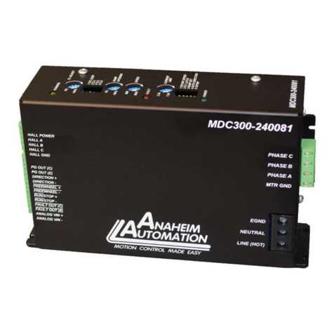
Dip Switch Panel 1 Settings
Dip Switch Panel 1: Speed Adjustment, Over Current, and Ramp settings
Internal/External Speed Control (Switch Panel 1 - Switch 1)
There are two ways to set the speed on this drive:
1. Use the on board potentiometer. To use the on board potentiometer,
set INT/EXT SPD switch (Switch Panel 1- Switch 1) to the ‘off’ position (default). The speed
is adjusted by setting the onboard speed potentiometer.
2. The second way is to use an external source. To use an external 10K potentiometer or
external voltage set INT/EXT SPD switch (Switch Panel 1- Swtich 1) to the ‘on’ position.
When INT/EXT SPD switch (Switch Panel 1- Switch 1) in the OFF Position:
The onboard speed potentiometer is used to control the speed of the motor. The motor speed increases
as the potentiometer is set from 0% - 100%.
When INT/EXT SPD switch (Switch Panel 1 - Switch 1) in the ON Position:
Either an external speed analog voltage or an external potentiometer can be used to set the motor speed.
For an external voltage, apply a +/- voltage on TB1 - pin 11 and the return on TB1 - pin 12. The motor
speed increases as the voltage is set from 0.1VDC to +5VDC or -0.1VDC to -5VDC. A -5VDC to +5VDC
voltagespancay be used to change the speedanddirectionofthe motor (seeAutoDirection(Switch Panel
1 - Switch 4). The motor will be stopped with an external speed analog voltage from -0.1VDC to 0.1VDC.
For an external potentiometer, connect the POT WIPER toTB1 - pin 11, POT(-) to TB1 - pin 12, and POT
(+) to an external +/-5V supply.
Fault Latch (Switch Panel 1 - Switch 2)
Over current protection can be provided by means of a over current latch function by setting the ‘FLT
LATCH’ switch, Switch Panel 1 - Switch 2 to the “on” position. If a motor current level exceeding the
current limit set by the internal current limit potentiometer is produced, an over current latch is activated,
shutting off the output and turning the fault output high (logic “1”). This driver is equipped with a FAULT
LED and Fault-out output to alert the user of the following conditions. To reset the MDC300-120301
driver from a latched condition, power down, allow 30 seconds for power to dissipate, then power up.
To diseable the fault latch, set FLT LATCH switch to the “off” position and the driver will have a cycle by
cycle current limiting protection.
