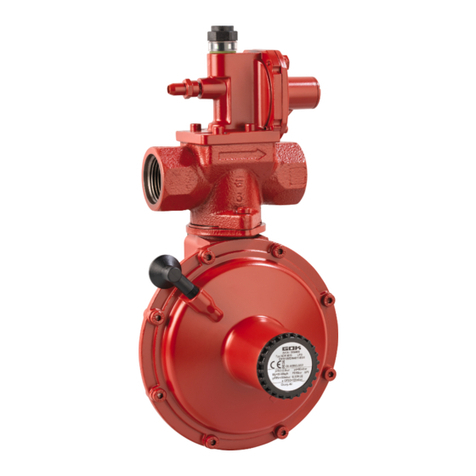
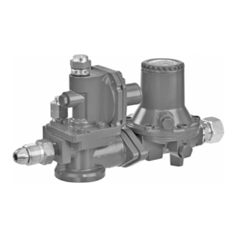
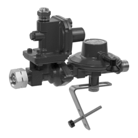
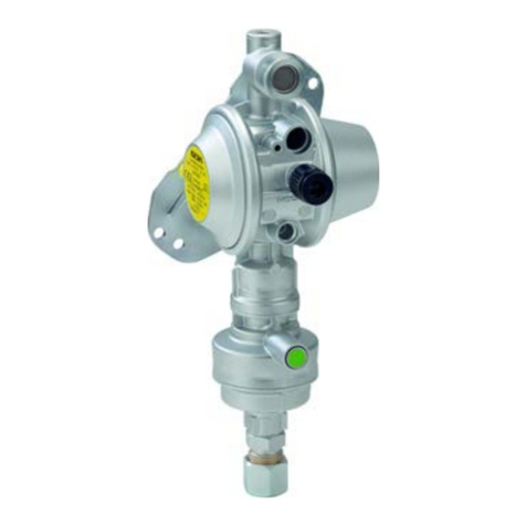
GOK VSR 0126 User instructions

Originalanleitung / Artikel-Nr. 01 267 50 c
Ausgabe 10.2015/Ersatz für Ausgabe 09.2014
Montage- und Bedienungsanleitung
Mitteldruckregler Typ VSR 0126
zum Direktanschluss an Gasbehälter
INHALTSVERZEICHNIS
ZU DIESER ANLEITUNG......................................................................................................................... 1
SICHERHEITSBEZOGENE HINWEISE ................................................................................................... 2
PRODUKTBEZOGENE SICHERHEITSHINWEISE.................................................................................. 2
ALLGEMEINE PRODUKTINFORMATION ............................................................................................... 2
BESTIMMUNGSGEMÄSSE VERWENDUNG .......................................................................................... 3
NICHT BESTIMMUNGSGEMÄSSE VERWENDUNG............................................................................... 3
QUALIFIKATION DER ANWENDER........................................................................................................ 3
AUFBAU .................................................................................................................................................. 3
VORTEILE UND AUSSTATTUNG............................................................................................................ 3
ANSCHLÜSSE......................................................................................................................................... 4
MONTAGE............................................................................................................................................... 5
DICHTHEITSKONTROLLE ...................................................................................................................... 6
INBETRIEBNAHME ................................................................................................................................. 6
BEDIENUNG............................................................................................................................................ 7
FEHLERBEHEBUNG ............................................................................................................................... 7
WARTUNG .............................................................................................................................................. 7
AUSTAUSCH........................................................................................................................................... 8
INSTANDSETZUNG ................................................................................................................................ 8
AUSSERBETRIEBNAHME ...................................................................................................................... 8
ENTSORGEN .......................................................................................................................................... 8
TECHNISCHE DATEN............................................................................................................................. 8
LISTE DER ZUBEHÖRTEILE................................................................................................................... 9
GEWÄHRLEISTUNG ............................................................................................................................... 9
TECHNISCHE ÄNDERUNGEN................................................................................................................ 9
SERVICE ................................................................................................................................................. 9
ZU DIESER ANLEITUNG
•Diese Anleitung ist ein Teil des Produktes.
•Für den bestimmungsgemäßen Betrieb und zur Einhaltung der Gewährleistung
ist diese Anleitung zu beachten und dem Betreiber auszuhändigen.
•Während der gesamten Benutzung aufbewahren.
•Zusätzlich zu dieser Anleitung sind die nationalen Vorschriften, Gesetze und
Installationsrichtlinien zu beachten.

Mitteldruckregler Typ VSR 0126
2 / 10 Artikel-Nr. 01 267 50 c
SICHERHEITSBEZOGENE HINWEISE
Ihre Sicherheit und die Sicherheit anderer ist uns sehr wichtig. Wir haben viele wichtige
Sicherheitshinweise in dieser Montage- und Bedienungsanleitung zur Verfügung gestellt.
Lesen und beachten Sie alle Sicherheitshinweise sowie Hinweise.
Dies ist das Warnsymbol. Dieses Symbol warnt vor möglichen Gefahren, die den
Tod oder Verletzungen für Sie und andere zur Folge haben können. Alle
Sicherheitshinweise folgen dem Warnsymbol, auf dieses folgt entweder das Wort
„GEFAHR", „WARNUNG" oder „VORSICHT". Diese Worte bedeuten:
bezeichnet eine Personengefährdung mit einem hohen Risikograd.
Hat Tod oder eine schwere Verletzung zur Folge.
bezeichnet eine Personengefährdung mit einem mittleren Risikograd.
Hat Tod oder eine schwere Verletzung zur Folge.
bezeichnet eine Personengefährdung mit einem niedrigen Risikograd.
Hat eine geringfügige oder mäßige Verletzung zur Folge.
bezeichnet einen Sachschaden.
Hat eine Beeinflussung auf den laufenden Betrieb.
bezeichnet eine Information bezeichnet eine Handlungsaufforderung
PRODUKTBEZOGENE SICHERHEITSHINWEISE
Ausströmendes Flüssiggas (Kategorie 1):
•ist extrem entzündbar
•kann zu Explosionen führen
•schwere Verbrennungen bei direktem Hautkontakt
Verbindungen regelmäßig auf Dichtheit prüfen!
Bei Gasgeruch und UndichtheitFlüssiggasanlage sofort außer Betrieb nehmen!
Zündquellen oder elektrische Geräte außer Reichweite halten!
Entsprechende Gesetze und Verordnungen beachten!
Druckregler ohne Überdruck-Sicherheitsabsperreinrichtung OPSO (SAV) dürfen in
Deutschland in gewerblichen Flüssiggasanlagen nur dann eingesetzt werden, wenn
der Nenndruck des Gasgerätes mindestens dem Absicherungsdruck des in
Fließrichtung vorgeschalteten Druckreglers entspricht!
ALLGEMEINE PRODUKTINFORMATION
Der Druckregler hält den auf dem Typschild angegebenen Ausgangsdruck konstant,
unabhängig von Schwankungen des Eingangsdruckes und Änderungen von Durchfluss und
Temperatur innerhalb festgelegter Grenzen.
Der Druckregler kann je nach Ausführung werkseitig fest eingestellt oder einstellbar sein. Der
Druckregler besitzt optional zusätzliche Sicherheitseinrichtungen.
Bei Feuchtigkeit in der Versorgungsanlage kann es zu einem Vereisen des Druckreglers
kommen. Um Vereisungen zu verhindern, wird die Verwendung der Reglerheizung
Typ ES2000 (Bestell-Nr. 05 220 00) empfohlen.

Mitteldruckregler Typ VSR 0126
Artikel-Nr. 01 267 50 c 3 / 10
BESTIMMUNGSGEMÄSSE VERWENDUNG
Betriebsmedien
•Flüssiggas (Gasphase)
Eine Liste der Betriebsmedien mit Angabe der Bezeichnung,
der Norm und des Verwendungslandes erhalten Sie im Internet unter
www.gok-online.de/de/downloads/technische-dokumentation.
Betreiberort
•Betrieb im Innen- und Außenbereich
Bei Anwendungen im Freien muss das Produkt so angeordnet oder geschützt
werden, dass kein Tropfwasser eindringen kann.
Der Einbau unter einer Behälter-Schutzhaube bzw. in einen Reglerschrank oder
Schutzkasten wird empfohlen.
Einbauort
•Montage erfolgt direkt auf dem Gasbehälter
Für den Einbau in einen Domschacht wird empfohlen:
Einbau von Ent- und Belüftungsset (Bestell-Nr. 02 063 17).
Verhindert das Eindringen von Wasser in den Druckregler.
NICHT BESTIMMUNGSGEMÄSSE VERWENDUNG
Jede Verwendung, die über die bestimmungsgemäße Verwendung hinausgeht:
•z. B. Betrieb mit anderen Betriebsmedien, Drücken
•Verwendung von Gasen in der Flüssigphase
•Einbau entgegen der Durchflussrichtung
•Änderungen am Produkt oder an einem Teil des Produktes
QUALIFIKATION DER ANWENDER
Dieses Produkt darf nur von qualifiziertem Fachpersonal installiert werden. Hierbei handelt es
sich um Personal, das mit Aufstellung, Einbau, Inbetriebnahme, Betrieb und Wartung dieses
Produktes vertraut ist.
Arbeitsmittel und überwachungsbedürftige Anlagen dürfen selbstständig nur von Personen
bedient werden, die das 18. Lebensjahr vollendet haben, körperlich geeignet sind und die
erforderlichen Sachkenntnisse besitzen oder von einer befähigten Person unterwiesen
wurden. Eine Unterweisung in regelmäßigen Abständen, mindestens jedoch jährlich, wird
empfohlen.
VORTEILE UND AUSSTATTUNG
Option Überdruck-Abblaseventil PRV
Das Überdruck-Abblaseventil PRV - (Pressure Relief Valve), im Weiteren PRV genannt -ist
eine im Druckregler eingebaute, selbsttätig wirkende Sicherheitseinrichtung mit begrenztem
Durchfluss. Das PRV schützt die angeschlossenen Verbraucher vor unzulässig hohem Druck.
Entsteht auf der Ausgangsseite ein unzulässig hoher Druck, z. B. durch hohe Temperaturen,
öffnet das PRV und bläst den Überdruck über die Atmungsöffnung ab. Nach dem Druckabbau
schließt das PRV selbsttätig. Es ist eine Verbindung ins Freie herzustellen (Abblaseleitung),
wenn ein Druckregler mit einem PRV in einem Gebäude, einer Umhausung oder einem
anderen möglicherweise gefährdeten Bereich betrieben werden soll.
Der Druckregler mit PRV ist auf dem Typschild mit „PRV“ gekennzeichnet.
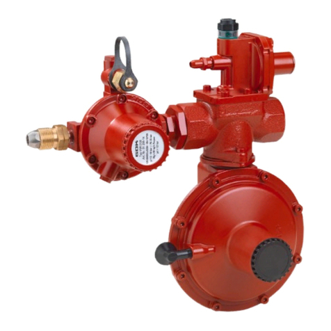
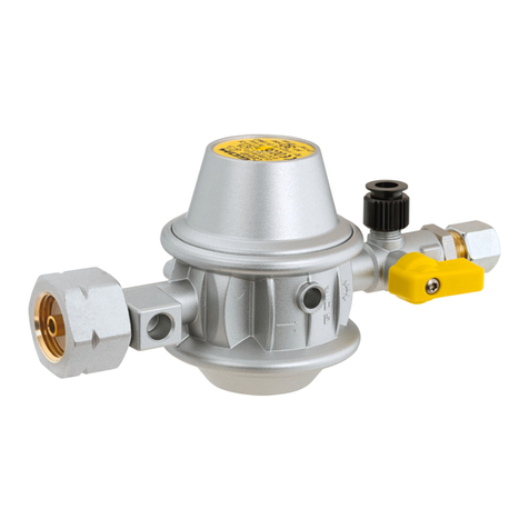
Mitteldruckregler Typ VSR 0126
4 / 10 Artikel-Nr. 01 267 50 c
Filtersieb im Eingangsanschluss des Druckreglers
Im Flüssiggas können Fremdkörper, z. B. Schmutz, enthalten sein. Diese werden ab einer
bestimmten Größe von dem Filtersieb im Eingangsanschluss gefiltert. Wird das Flüssiggas
nicht gefiltert, erhöht sich der Verschleiß der Flüssiggasanlage, bis hin zu deren Ausfall.
Siehe FEHLERBEHEBUNG.
Option Manometer
Das Produkt kann mit einem Manometer zur Anzeige des Ausgangsdruckes ausgestattet
sein.
Option Schutzmembrane
Das Produkt kann mit einer Schutzmembrane gegen Vereisung der Reglermembrane
ausgestattet sein.
Option Insektenschutzvorrichtung mit Filtersieb
In vorgesehene Atmungsöffnung auf Entlüftungsstutzen RST 8 mm stecken
bzw. in Innengewinde G 1/8 einschrauben.
Regelmäßige Kontrolle des Siebes auf freien Durchgang. Ein verstopftes Sieb
kann zu erhöhten oder zu geringeren
Ausgangsdrücken führen. Gegebenenfalls reinigen oder
austauschen.
AUFBAU
Eingangsanschluss
Ausgangsanschluss
Manometer (optional)
Verschlussdeckel, fest eingestellt
Handrad, verstellbar
Gewindestift im Handrad
Öffnung für Insektenschutzvorrichtung
(optional)
ANSCHLÜSSE
Eingang
wahlweise
Handelsname und Abmessung
nach Norm
Montagehinweis
Zylindrisches Innengewinde
•G.37 = IG G 1/4, G 3/8, G 1/2, G 3/4 oder G 1
•Zur Aufnahme einer
Einschraubverschraubung mit O-Ring
Italienischer Anschluss (Ital.A)
•mit Gummidichtung und Überwurfmutter
•G.1 = Gewinde W 20 x 1/14 LH
Schlüsselweite
SW 25
Sechskant

Mitteldruckregler Typ VSR 0126
Artikel-Nr. 01 267 50 c 5 / 10
Eingang
wahlweise
Handelsname und Abmessung
nach Norm
Montagehinweis
US-POL (POL)
•mit Dichtnippel und Überwurfschraube
•G.9 = Gewinde 0,880-14 NGO-LH
Schlüsselweite
SW 24
Sechskant
Schneidringverschraubung RVS
•G.22 = RVS 12, RVS 15, RVS 18, RVS 22,
RVS 28, RVS 35
Ausgang
wahlweise
Handelsname und Abmessung
nach Norm
Montagehinweis
Einschraubverschraubung
•H.22 = IG G 1/4, G 3/8, G 1/2, G 3/4 oder G
1
•Zur Aufnahme einer
Einschraubverschraubung mit O-Ring.
Schneidringverschraubung RVS
•H.8 = RVS 12, RVS 15, RVS 18, RVS 22,
RVS 28
•H.9 = RVS 8, RVS 10
Alternativ sind noch andere Anschlüsse möglich. Alle G. und H. Anschlüsse nach EN 16129.
MONTAGE
Vor der Montage ist das Produkt auf Transportschäden und Vollständigkeit zu prüfen.
Die MONTAGE ist von einem Fachbetrieb vorzunehmen!
Alle nachfolgenden Hinweise dieser Montage- und Bedienungsanleitung müssen vom
Fachbetrieb, Betreiber und Bediener beachtet, eingehalten und verstanden werden.
Voraussetzung für ein einwandfreies Funktionieren der Anlage ist eine fachgerechte
Installation unter Beachtung der für Planung, Bau und Betrieb der Gesamtanlage gültigen
technischen Regeln.
Verletzungsgefahr durch herausgeblasene Metallspäne!
Metallspäne können Ihre Augen verletzen.
Schutzbrille tragen!
Funktionsstörungen durch Rückstände!
Die ordnungsgemäße Funktion ist nicht gewährleistet.
Sichtkontrolle auf eventuelle Metallspäne oder sonstige Rückstände in den Anschlüssen
vornehmen!
Metallspäne oder sonstige Rückstände durch vorsichtiges Ausblasen unbedingt entfernen!
Die Montage ist gegebenenfalls mit einem geeigneten Werkzeug vorzunehmen.
Bei Schraubverbindungen muss immer mit einem zweiten Schlüssel am Anschlussstutzen
gegengehalten werden.
Ungeeignete Werkzeuge, wie z. B. Zangen, dürfen nicht verwendet werden!

Mitteldruckregler Typ VSR 0126
6 / 10 Artikel-Nr. 01 267 50 c
Beschädigung des Produktes durch falsche Einbaurichtung!
Die ordnungsgemäße Funktion ist nicht gewährleistet.
Einbaurichtung beachten (diese ist auf dem Produkt erkennbar mit einem Pfeil
gekennzeichnet)!
Schraubverbindungen
Beschädigung des Behälterreglers durch falsche Montage!
Kann zu Gasaustritt und Funktionsstörungen führen.
Montageschritte beachten, um Undichtheiten zu vermeiden!
Behälterregler darf nicht unter Spannung montiert werden!
Behälterregler nach Anziehen des Eingangsanschlusses nicht mehr verdrehen!
Nachziehen von Anschlüssen nur in vollständig drucklosem Zustand!
Montageschritte beispielhaft für Behälterregler mit US-POL-Anschluss
(British POL-Anschluss und POL-Anschluss weich)
1. Auf die konische Dichtfläche des POL-Stutzens und auf das POL-Gewinde einen Tropfen
Öl geben.
2. POL-Anschluss handfest am Gasentnahmeventil des Gasbehälters anschrauben.
3. Rohrleitung am Ausgangsstutzen festziehen, an der Schlüsselfläche der
Rohrverschraubung gegenhalten.
4. POL-Anschluss am Gasentnahmeventil fest anziehen.
Bei der Montage darauf achten, dass das Gasentnahmeventil und die
Rohrleitung in einer Flucht montiert werden! Behälterregler nicht unter Spannung montieren!
Wir empfehlen die „Reglerabstützung für CE-Behälter“, Bestell-Nr. 02 510 40.
DICHTHEITSKONTROLLE
Verbrennungs- oder Brandgefahr!
Schwere Hautverbrennungen oder Sachschaden.
Keine offenen Flammen zur Prüfung verwenden!
Vor der Inbetriebnahme sind die Anschlüsse des Gastanks auf Dichtheit zu prüfen!
1. Alle Absperrarmaturen des angeschlossenen Verbrauchgerätes schließen.
2. Anschließend Gasentnahmeventil langsam öffnen.
3. Ist eine Sicherheitseinrichtung (z.B. SBS, EFV) zu dem angeschlossenen Verbraucher
zwischengeschaltet, ist diese bei der Dichtheitsprüfung zu öffnen.
4. Alle Anschlüsse mit schaumbildenden Mitteln nach EN 14291
(z. B. Lecksuchspray, Bestell-Nr. 02 601 00) einsprühen.
5. Dichtheit prüfen, indem auf Blasenbildung des schaumbildenden Mittels geachtet wird.
Bilden sich weitere Blasen, müssen die Anschlüsse nachgezogen
werden (siehe MONTAGE). Falls sich die Undichtheiten nicht beseitigen lassen, darf
das Produkt nicht in Betrieb genommen werden.
INBETRIEBNAHME
Das Produkt ist sofort betriebsbereit.
1. Alle Absperrarmaturen der Gasgeräte müssen geschlossen sein.
2. Gasentnahmeventil langsam öffnen.
3. Montage- und Bedienungsanleitung des Gasgerätes beachten!

Mitteldruckregler Typ VSR 0126
Artikel-Nr. 01 267 50 c 7 / 10
BEDIENUNG
Arretiereinrichtung am Handrad, bei verstellbarer Ausführung
1. Handrad lösen: Gewindestift des Handrads mit
einem Innensechskantschlüssel herausdrehen.
2. Ausgangsdruck einstellen: gewünschten Ausgangsdruck durch
Drehen des Handrads einstellen (Rechtsdrehung = Erhöhung
des Ausgangsdruckes)
Der Ausgangsdruck kann auf dem Manometer
(optional) abgelesen werden.
3. Handrad arretieren: Gewindestift mit einem
Innensechskantschlüssel in der vorgesehenen
Kerbe am Gehäuse des Handrads festziehen.
FEHLERBEHEBUNG
Fehlerursache
Maßnahme
Gasgeruch
Ausströmendes Flüssiggas
ist extrem entzündbar!
Kann zu Explosionen führen.
Gaszufuhr schließen!
Keine elektrischen Schalter betätigen!
Nicht im Gebäude telefonieren!
Räume gut belüften!
Flüssiggasanlage außer Betrieb nehmen!
Fachbetrieb beauftragen!
Abnormales Flammenbild bei
fest eingestelltem Druckregler
Nennausgangsdruck des Druckreglers mit
Nennanschlussdruck des angeschlossenen Verbrauchers
vergleichen:
bei Nichtübereinstimmung, Druckregler oder
Gasgerät austauschen
Ausgangsdruck messen; Ausgangsdruck liegt nicht
innerhalb der vorgegebenen Grenzen:
Anlagenkonzeption prüfen
Druckregler ist beschädigt, austauschen
Abnormales Flammenbild
einstellbarer Druckregler
Nennausgangsdruck des Druckreglers mit
Nennanschlussdruck des angeschlossenen Verbrauchers
vergleichen:
bei Nichtübereinstimmung, Druckregler auf
Nennanschlussdruck einstellen
Ausgangsdruck des Druckreglers messen; Ausgangsdruck
liegt nicht innerhalb der vorgegebenen Grenzen:
Anlagenkonzeption prüfen
Ausgangsdruck neu einstellen
Kein Gasdurchfluss
Gasflaschenventil oder Absperrarmaturen öffnen
Druckregler ist beschädigt, austauschen
Manometer zeigt falsche
Werte an oder funktioniert
nicht
Manometer ist beschädigt:
nur im vollkommen drucklosen Zustand der
Flüssiggasanlage austauschen

Mitteldruckregler Typ VSR 0126
8 / 10 Artikel-Nr. 01 267 50 c
WARTUNG
Es wird empfohlen, die Anlage mit Druckregler in gewissen Zeitabständen, z. B. einmal im
Jahr, auf Dichtheit und Funktion zu prüfen.
AUSTAUSCH
Bei Anzeichen jeglichen Verschleißes und jeglicher Zerstörung des Produktes oder eines
Teiles des Produktes muss dieses ausgetauscht werden.
Bei Austausch des Produktes Schritte MONTAGE, DICHTHEITSKONTROLLE und
INBETRIEBNAHME beachten!
Um unter normalen Betriebsbedingungen die einwandfreie Funktion der Installation zu
gewährleisten, wird empfohlen, die Einrichtung vor Ablauf von 10 Jahren nach dem
Herstellungsdatum auszutauschen.
Im gewerblichen Bereich nach DGUV Vorschrift 79 sind Teile von Verbrauchsanlagen,
die Verschleiß und Alterung*unterliegen, nach 8 Jahren auszutauschen. Dies gilt
nicht, wenn die ordnungsgemäße Beschaffenheit durch einen Sachkundigen bestätigt
worden ist.
*Anlagenteile, die Verschleiß oder Alterung unterliegen, sind z.B. Membranen,
automatische oder manuelle Umschaltventile, Druckregler, Schlauchleitungen.
Beschädigung des Produktes durch Überflutung!
Verursacht Korrosion und Funktionsstörungen des Druckreglers.
Druckregler nach einer Überflutung austauschen!
INSTANDSETZUNG
Führen die unter FEHLERBEHEBUNG genannten Maßnahmen nicht zur ordnungsgemäßen
Wiederinbetriebnahme und liegt kein Auslegungsfehler vor, muss das Produkt zur Prüfung an
den Hersteller gesandt werden. Bei unbefugten Eingriffen erlischt die Gewährleistung.
AUSSERBETRIEBNAHME
Behälterventil und dann Absperrarmaturen des Gasgerätes schließen.
Bei Nichtbenutzung der Flüssiggasanlage alle Ventile geschlossen halten.
ENTSORGEN
Um die Umwelt zu schützen, dürfen unsere Produkte nicht mit dem Hausmüll
entsorgt werden.
Das Produkt ist über örtliche Sammelstellen oder Wertstoffhöfe zu entsorgen.
TECHNISCHE DATEN
Eingangsdruck p
1 bis 16 bar
Ausgangsdruck p
d
fest eingestellt: zwischen 0,7 und 2,0 bar
verstellbar: von 0,5 bis 2,0 bar (4 bar)
Nenndurchfluss Mg
maximal 60 kg/h
Maximal zulässiger Druck PS
25 bar
Umgebungstemperatur
-20 °C bis +50 °C
Option Ansprechdruck PRV
siehe Typschild
Gehäusewerkstoff
Zinkdruckguss ZP0410
Weitere technische Daten oder Sondereinstellungen siehe Typschild des Druckreglers!

Mitteldruckregler Typ VSR 0126
Artikel-Nr. 01 267 50 c 9 / 10
LISTE DER ZUBEHÖRTEILE
Produktbezeichnung
Bestell-Nr.
Reglerheizung Typ ES2000
05 220 00
Ent- und Belüftungsset für Typ VSR 0126
02 063 17
GEWÄHRLEISTUNG
Wir gewähren für das Produkt die ordnungsgemäße Funktion und Dichtheit
innerhalb des gesetzlich vorgeschriebenen Zeitraums. Der Umfang unserer
Gewährleistung richtet sich nach § 8 unserer Liefer- und Zahlungsbedingungen.
TECHNISCHE ÄNDERUNGEN
Alle Angaben in dieser Montage- und Bedienungsanleitung sind die Ergebnisse der
Produktprüfung und entsprechen dem derzeitigen Kenntnisstand sowie dem Stand der
Gesetzgebung und der einschlägigen Normen zum Ausgabedatum. Änderungen der
technischen Daten, Druckfehler und Irrtümer vorbehalten. Alle Abbildungen dienen
illustrativen Zwecken und können von der tatsächlichen Ausführung abweichen.
SERVICE
Unter der Adresse www.gok-blog.de finden Sie Antworten auf besonders häufig
gestellte Fragen aus den Themenbereichen Flüssiggasanlagen, Flüssiggas in der
Freizeit, Ölfeuerungsanlagen und Tankmanagement.

Mitteldruckregler Typ VSR 0126
Regler- und Armaturen-Gesellschaft mbH & Co. KG
Obernbreiter Straße 2-18 • 97340 Marktbreit / Germany
Tel.: +49 9332 404-0 • Fax: +49 9332 404-43
E-Mail: info@gok-online.de • www.gok-online.de • www.gok-blog.de
10 / 10 Artikel-Nr. 01 267 50 c
NOTIZEN

Translation of the original operating instructions / part no. 01 267 50 c
Version 10.2015/Replaces version 09.2014
Assembly and operating manual
Medium pressure regulator type VSR 0126
to connect directly to gas tanks
CONTENTS
ABOUT THE MANUAL............................................................................................................................. 1
SAFETY ADVICE..................................................................................................................................... 2
PRODUCT-RELATED SAFETY ADVICE ................................................................................................. 2
GENERAL PRODUCT INFORMATION.................................................................................................... 2
INTENDED USE ...................................................................................................................................... 2
INAPPROPRIATE USE............................................................................................................................ 3
USER QUALIFICATION........................................................................................................................... 3
ADVANTAGES AND EQUIPMENT .......................................................................................................... 3
DESIGN ................................................................................................................................................... 4
CONNECTIONS....................................................................................................................................... 4
ASSEMBLY.............................................................................................................................................. 5
LEAK CHECK .......................................................................................................................................... 6
START-UP ............................................................................................................................................... 6
OPERATION............................................................................................................................................ 6
TROUBLESHOOTING ............................................................................................................................. 6
MAINTENANCE ....................................................................................................................................... 7
REPLACEMENT ...................................................................................................................................... 7
RESTORATION ....................................................................................................................................... 7
SHUT-DOWN........................................................................................................................................... 8
DISPOSAL ............................................................................................................................................... 8
TECHNICAL DATA .................................................................................................................................. 8
LIST OF ACCESSORIES ......................................................................................................................... 8
WARRANTY ............................................................................................................................................ 9
TECHNICAL CHANGES .......................................................................................................................... 9
SERVICE ................................................................................................................................................. 9
NOTES .................................................................................................................................................. 10
ABOUT THE MANUAL
•This manual is part of the product.
•This manual must be observed and handed over to the operator to ensure that
the component operates as intended and to comply with the warranty terms.
•Keep it in a safe place while you are using the product.
•In addition to this manual, please also observe national regulations, laws and
installation guidelines.

Medium pressure regulator type VSR 0126
2 / 10 part no. 01 267 50 c
SAFETY ADVICE
Your safety and the safety of others are very important to us. We have provided many
important safety messages in this assembly and operating manual.
Always read and obey all safety messages.
This is the safety alert symbol.
This symbol alerts you to potential hazards that can kill or hurt you and others.
All safety messages will follow the safety alert symbol and either the word
“DANGER”, “WARNING”, or “CAUTION”. These words mean:
describes a personal hazard with a high degree of risk.
May result in death or serious injury.
describes a personal hazard with a medium degree of risk.
May result in death or serious injury.
describes a personal hazardwith a low degree of risk.
May result in minor or moderate injury.
describes material damage.
Has an effect on ongoing operation.
describes a piece of information
describes a call to action
PRODUCT-RELATED SAFETY ADVICE
Escaping liquid petroleum gas (category 1):
•is highly flammable
•may cause explosions
•severe burns in case of direct skin contact
Regularly check connections for leak-tightness.
If you smell gas or detect a leak, shut the system down immediately.
Keep ignition sources and electrical devices out of reach.
Observe applicable laws and regulations.
GENERAL PRODUCT INFORMATION
The product keeps the specified outlet pressure constant within defined limits regardless of
fluctuations in the inlet pressure and changes in flow and temperature.
Depending on the model, the pressure regulator can be set in the factory or can be
adjustable. The pressure regulator has additional safety equipment options.
Under certain circumstances, the pressure regulator may ice up. To prevent
icing, we recommend you use regulator heating type ES2000 (Part No. 05 220 00).
INTENDED USE
Operating media
•LPG (gas phase)
You will find a
list of operating media
with descriptions, the relevant
standards and the country in which they are used in the Internet at
www.gok-online.de/de/downloads/technische-dokumentation.

Medium pressure regulator type VSR 0126
part no. 01 267 50 c 3 / 10
Place of operation
•operate indoors and outdoors
For outdoor applications, the product must be located or protected so that no
dripping water can enter. We recommend installation in under a hood and in a control cabinet,
respectively, or in a housing.
Installation location
•The device is installed directly on to the gas tank
For installation in a dome, we recommend:
Installation of ventilation set (Part No. 02 063 17).
Prevents water getting into the pressure regulator.
INAPPROPRIATE USE
All uses exceeding the concept of intended use:
•e.g. operation using different media, pressures
•use of gases in the liquid phase
•installation against the flow direction
•changes to the product or parts of the product
USER QUALIFICATION
This product may be installed only by qualified experts. These are personnel who are familiar
with setting up, installing, starting up, operating and maintaining this product.
"Equipment and systems requiring supervision may be operated only by persons aged at
least 18, who are physically capable and who have the necessary specialist knowledge or
who have been instructed by a competent person. Instruction at regular intervals, but at least
once per year, is recommended."
ADVANTAGES AND EQUIPMENT
Filter screen in the inlet connection of the pressure regulator
LPG may contain foreign matter, such as dirt particles. Over a certain size, these particles are
trapped in the filter screen in the inlet connection. If the LPG is not filtered, wear and tear of
the LPG system is increased up to complete failure. See TROUBLESHOOTING.
Pressure relief valve (PRV) option
The pressure relief valve (PRV) is an automatic safety device with limited flow that is installed
in the pressure regulator to protect connected devices against inadmissible high pressures. If
there is inadmissible high pressure at the outlet side, for example due to high temperatures,
the PRV opens and relieves the excess pressure through the breather. When the pressure
falls, the PRV closes again automatically.
A connection to the open air must be created if a pressure regulator with PRV is to be
operated indoors, inside a housing or in any other areas that could be at risk.
"PRV" is marked on the type label of the pressure regulator.
Optional pressure gauge
The product can be equipped with a pressure gauge to show the outlet pressure.
Optional protective membrane
The product can be equipped with a protective membrane to prevent the regulator
membranes icing up.

Medium pressure regulator type VSR 0126
4 / 10 part no. 01 267 50 c
Optional insect protection device
Insert in the breather on the 8 mm vent socket or screw into the female
thread G 1/8.
Check regularly that the sieve is not blocked. A blocked sieve may increase or
decrease outlet pressures. Clean or replace as required.
DESIGN
Inlet connection
Outlet connection
Pressure gauge (optional)
Cap, non-adjustable
Handwheel, adjustable
Set screw in handwheel
Opening for insect protection device
(optional)
CONNECTIONS
Inlet,
optional
Trading name and dimensions
acc. to standard
Installation notes
Cylindrical female thread
•G.37 = FG 1/4, G 3/8, G 1/2, G 3/4 or G 1
•For a screw-in connector with O-ring
Italian connection
•with rubber gasket and cap nut
•G.1 = Thread W 20 x 1/14 ÜM
Spanner size 25
Hexagonal
US POL connection
•with sealing fitting and retaining screw
•G.9 = Thread 0.880-14 NGO lh
Spanner size 24
Hexagonal
Compression fitting
•G.22 = compr. fit 12, compr. fit 15,
compr. fit 18, compr. fit 22, compr. fit 28 or
compr. fit 35
More information
can be obtained on
the Internet or on
request.

Medium pressure regulator type VSR 0126
part no. 01 267 50 c 5 / 10
Outlet,
optional
Trading name and dimensions
acc. to standard
Installation notes
Screw-in connector
•H.22 = G 1/4, G 3/8, G 1/2, G 3/4 or G 1
•For a screw-in connector with O-ring
Compression fitting
•H.8 = compr. fit 12, compr. fit 15, compr. fit 18,
compr. fit 22, compr. fit 28, compr. fit 35
•H.9 = compr. fit 8, compr. fit 10
All G. and H. connections according to EN 16129. Other connections may also be used.
ASSEMBLY
Before assembly, check that the product is complete and has not suffered any damage during
transport.
ASSEMBLY must be carried out by a specialised company.
The specialised company and the operator must observe, comply with and understand all of
the following instructions in this assembly and operating manual. For the system to function
as intended, it must be installed professionally in compliance with the technical rules
applicable to the planning, construction and operation of the entire system.
Risk of injuries due to blown-out metal chips!
Metal chips may cause eye injuries.
Wear safety goggles!
Malfunctions caused by residues! Proper functioning is not guaranteed.
Visually check that there are no metal chips or other residues in the connections!
It is important that metal chips or other residues are blown out!
Install with suitable tools, if required.
Regarding screw connections, use a second spanner to brace against the connection nozzle.
Do not use unsuitable tools, such as pliers.
Product damaged through incorrect installation direction
Proper functioning is not guaranteed.
Observe the installation direction (marked on the product with an arrow ).
Screw connections
Tank regulator damaged through incorrect installation.
May cause gas leaks and malfunctioning.
Follow the correct sequence to prevent leaks.
Do not install the tank regulator under tension.
When you have tightened the POL coupling nut, do not twist the tank regulator any more.
Tighten connections only when they are not pressurised.
The installation steps are described using a pressure regulator with US POL
connection as an example (British POL connection and POL connection soft)
1. Apply a drop of oil to the conical sealing surface of the POL connector.
2. Screw the POL connection on to the withdrawal valve of the gas cylinder hand-tight.
3. Tighten the piping on the outlet nozzle while bracing against the flat of the pipe coupling.
4. Tighten the POL connector on the withdrawal valve.

Medium pressure regulator type VSR 0126
6 / 10 part no. 01 267 50 c
During installation make sure that the withdrawal valve and the piping are aligned. Do not
install the tank regulator under tension. We recommend the "regulator support for CE tanks",
Part no. 02 510 40.
LEAK CHECK
Risk of burning or fire
Serious burns to the skin or damage to property.
Do not use an open flame to check for leaks.
Before start-up, check the gas tank connections for leaks.
1. Close all shut-off fittings on connected devices.
2. Slowly open the withdrawal valve.
3. Spray all connections with a foam producing substance according
to EN 14291 (e.g. leak spray, Part no. 02 601 00).
4. Bubbles will form in the foam producing substance if there are any leaks.
If more bubbles form, re-
tighten the connections (see ASSEMBLY). If you
cannot stop the leaks, you must not use the product.
START-UP
The product is ready for use.
1. All shut-off fittings on the gas devices must be closed.
2. Slowly open the gas withdrawal valve.
3. Observe the assembly and operating instructions of the gas device!
OPERATION
Lock-in device on handwheel with adjustable version
1. Loosen handwheel: Unscrew the set screw of the handwheel
slightly using an Allen key.
2. Adjust the outlet pressure: Adjust the required outlet pressure
by turning the handwheel (turning clockwise = increases the
outlet pressure)
The outlet pressure can be seen on the pressure gauge.
3. Lock the handwheel: Tighten the set screw in the groove
on the housing of the handwheel with an Allen key.
TROUBLESHOOTING
Fault cause
Action
Gas smell
Leaking LPG is extremely
flammable.
Can cause explosions.
Close the gas supply.
Do not use any electric switches.
Do not use a phone in the building.
Ventilate rooms well.
Shut down the LPG system.
Contact a specialised company.
No gas flow.
Open the gas cylinder valve or the shut-off fittings.

Medium pressure regulator type VSR 0126
part no. 01 267 50 c 7 / 10
Fault cause
Action
Pressure gauge indicates
incorrect values or is not
working at all.
Pressure gauge is defective.
Replace only when the LPG system is completely
de-pressurised.
Abnormal flame pattern of
non-adjustable pressure
regulator
Compare the nominal outlet pressure with the nominal
connection pressure:
if they do not correspond, replace the pressure regulator
or the gas appliance
Measure the outlet pressure; outlet pressure is not within
the specified limits:
check the system configuration
pressure regulator is defective, replace
check the gas filter
Abnormal flame pattern
of adjustable pressure
regulator
Compare the nominal outlet pressure of the pressure
regulator with that of the connected device:
If they do not match, adjust the pressure regulator to the
nominal connection pressure
Measure the outlet pressure of the pressure regulator;
outlet pressure is not within the specified limits.
Check the system configuration
Readjust the outlet pressure
MAINTENANCE
It is advisable to check the system with the pressure regulator for leaks and to ensure that it is
functioning properly occasionally, such as once per year.
REPLACEMENT
If there is any sign of wear or if the product or parts thereof are damaged, it must be replaced.
When the product has been replaced, observe the steps ASSEMBLY, LEAK TESTING and
START-UP.
To ensure that the installation works faultlessly under normal operating conditions, it is
recommended that you replace the device within 10 years of the date of manufacture.
In commercial applications, according to DGUV regulation 79, parts of consumer
units that are subject to wear and ageing*must be replaced after 8 years. This does not apply
if the proper condition has been confirmed by an expert.
* System parts that are subject to wear or ageing are, for example, membranes, automatic
and manual changeover valves, pressure regulators, hoses assemblies.
Product damaged due to flooding!
This causes corrosion and malfunctions to the pressure regulator.
Replace the pressure regulator following flooding!
RESTORATION
If the actions described in TROUBLESHOOTING do not lead to a proper restart and if there is
no dimensioning problem, the product must be sent to the manufacturer to be checked. Our
warranty does not apply in cases of unauthorised interference.

Medium pressure regulator type VSR 0126
8 / 10 part no. 01 267 50 c
SHUT-DOWN
Close the cylinder valve and then the shut-off devices of the consumer unit. When the system
is not used, all valves must be kept closed.
DISPOSAL
To protect the environment, our products may not be disposed of along with
household waste.
The product must be disposed of via a local collection station or a recycling station.
TECHNICAL DATA
Inlet pressure p
1 to 16 bar
Outlet pressure p
d
set: between 0.7 and 2.0 bar.
adjustable: from 0.5 to 2.0 bar (4 bar)
Nominal flow rate Mg
max. 60 kg/h
Maximum admissible pressure
PS 25 bar
Ambient temperature
-20 °C to +50 °C
Optional response pressure
PRV
see type label
Housing material
ZP0410
Refer to the type label of the pressure regulator for more technical data and special
settings!
LIST OF ACCESSORIES
Product name
Order no.
Regulator heating type ES2000
05 220 00
Ventilation set for type VSR 0126
02 063 17

Medium pressure regulator type VSR 0126
part no. 01 267 50 c 9 / 10
WARRANTY
We guarantee that the product will function as intended and will not leak during
the legally specified period. The scope of our warranty is based on Section 8 of
our terms and conditions of delivery and payment.
TECHNICAL CHANGES
All the information contained in this assembly and operating manual is the result of product
testing and corresponds to the level of knowledge at the time of testing and the relevant
legislation and standards at the time of issue. We reserve the right to make technical changes
without prior notice. Errors and omissions excepted. All figures are for illustration purposes
only and may differ from actual designs.
SERVICE
At the web address www.gok-blog.de you can find answers to frequently asked
questions relating to the topics of LPG systems, liquefied gas for leisure time use,
oil firing installations and tank management.

Medium pressure regulator type VSR 0126
Regler- und Armaturen-Gesellschaft mbH & Co. KG
Obernbreiter Straße 2-18 • 97340 Marktbreit / Germany
Tel.: +49 9332 404-0 • Fax: +49 9332 404-43
E-Mail: info@gok-online.de • www.gok-online.de • www.gok-blog.de
10 / 10 part no. 01 267 50 c
NOTES
Other manuals for VSR 0126
2
Table of contents
Languages:
Other GOK Controllers manuals

GOK
GOK VSR 0523 User instructions

GOK
GOK FL 90-4 User instructions

GOK
GOK ES2000 User manual

GOK
GOK Caramatic Drive One User instructions

GOK
GOK BHK 052 User instructions

GOK
GOK EN61-DS.2 User instructions

GOK
GOK ODR User instructions

GOK
GOK MIC Installation and operating instructions

GOK
GOK NDR 0515 User instructions

GOK
GOK FL 90-4 User instructions
Popular Controllers manuals by other brands

Watlow
Watlow Micro-Based Autotuning Control SERIES... user manual

Agilent Technologies
Agilent Technologies 929-0022 instruction manual

Samson
Samson 3767 Mounting and operating instructions

C2AI
C2AI MVE2 65 Series manual

Johnson Controls
Johnson Controls VMA1615 installation instructions

Siemens
Siemens RXB39.1 manual