Analog Devices MAXREFDES106# User manual

©2022 Analog Devices, Inc. All rights reserved.
11//23
(Rev 1) 1
MAXREFDES106# Health Sensor Platform 4.0
Features
The MAXREFDES106# is a chest-worn device
that displays and logs biometric data. The
platform includes the following innovative
features:
ECG-Based Heart Rate
Optical PPG-based SpO2
BioZ-Based Respiration Rate
Skin and Ambient Temperature
Location Finder to Determine the Best
Placement Location
Rechargeable 190mAh Battery
General Description
The MAXREFDES106# is a vital sign monitoring
platform in a chest-patch form factor. The
platform uses algorithms and high sensitivity
photoplethysmography (PPG),
electrocardiogram (ECG), bioimpedance (BioZ),
and temperature biosensor measurements to
calculate heart rate (HR), respiration rate (RR),
and blood oxygenation (SpO2). The vital signs
data can be displayed on a Microsoft Windows®
graphical user interface (GUI) in real-time and
logged to a local file for further study.
The patch is designed for long-term passive
monitoring with a runtime of one day on a single
charge. The PPG acquisition system consists of
a red and infrared (IR) light emitter source and
two photodiode receivers. The MAX86178 AFE
includes dual high-resolution optical readout
signal-processing channels with robust ambient-
light cancellation, which is ideal for SpO2
measurement. PPG and accelerometer data are
processed by the embedded algorithm inside of
the MAX32674C algorithm hub (Algo Hub) to
calculate SpO2. The ECG acquisition system
has three electrodes for continuous ECG, and
four electrodes for BioZ monitoring. The PC GUI
contains algorithms to filter the ECG and BioZ
data, and to calculate heart rate, respiration
rate, blood stroke volume, and cardiac output.
All algorithms are not publicly available. The
exception to this is the SpO2 algorithm, which is
released as an .msbl file that is flashed to the
MAX32674C.
The patch also features measurements for both
skin temperature and ambient temperature
using two low-power consumption, highly
accurate MAX30210 temperature sensors.
The real-time vital signs can be viewed and
logged through Low Energy Bluetooth®
communications available from the PC GUI
running on a Microsoft Windows PC.
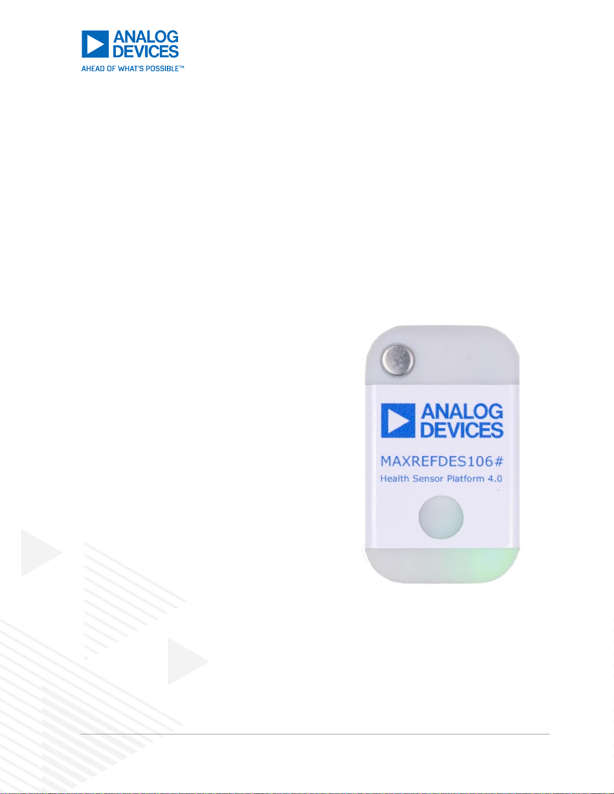
Figure 1. MAXREFDES106# Vital Sign
Monitoring Patch

©2022 Analog Devices, Inc. All rights reserved.
11//23
(Rev 1) 2
MAXREFDES106# Health Sensor Platform 4.0
Contents
Features........................................................................................................................................1
General Description......................................................................................................................1
System Architecture......................................................................................................................4
Push Button Description............................................................................................................5
Color Definitions for the Status LED..........................................................................................5
Location Quality Definitions for the Location Finder LED..........................................................6
Included Components ...............................................................................................................6
Additional Components Required..............................................................................................7
Updating the Firmware..................................................................................................................8
Updating the MAX32666 Host MCU Firmware (.bin) ................................................................8
Required Equipment..............................................................................................................8
Procedure..............................................................................................................................8
Updating the MAX32674C Algo Hub Microcontroller Coprocessor Firmware (.msbl).............10
Installing the MAXREFDES106# Health Sensor Platform PC GUI .........................................12
Charge the Device and Run the MAXREFDES106# Health Sensor Platform PC GUI...............15
Orientation of the USB-C 7-Lead Electrode Cable to the MAXREFDES106#............................18
Measurements............................................................................................................................19
Photoplethysmogram (PPG) ...................................................................................................19
Electrocardiogram (ECG)........................................................................................................21
Bioimpedance (Bio-Z)..............................................................................................................24
Algorithms ...............................................................................................................................26
Impedance Cardiography (ICG) ..............................................................................................26
Bio-impedance Analysis (BIA).................................................................................................32
Heart Rate (HR) ......................................................................................................................34
Blood Oxygen Saturation (SpO2) ............................................................................................37
Temperature Sensors..............................................................................................................39
PC GUI Tabs...........................................................................................................................40
Location Finder Tab.............................................................................................................40

©2023 Analog Devices, Inc. All rights reserved.
3
MAXREFDES106# Health Sensor Platform 4.0
PLL Tab...............................................................................................................................41
PPG Mode Tab....................................................................................................................43
PPG Settings Tab................................................................................................................45
PPG Measurement Settings................................................................................................46
ECG Channel Tab ...............................................................................................................49
ECG Mux Tab......................................................................................................................52
ECG Lead OFF Tab.............................................................................................................53
ECG RLD Tab......................................................................................................................55
BioZ Drive Tab.....................................................................................................................57
BioZ Receive Tab................................................................................................................59
BioZ Mux Tab ......................................................................................................................61
BioZ Calibration Tab............................................................................................................62
BIA Tab................................................................................................................................65
Temperature Tab.................................................................................................................66
Plots Tab..............................................................................................................................67
Register Tab........................................................................................................................68
Data Logging...............................................................................................................................70
Logging to a File......................................................................................................................70
Logging to Flash Memory........................................................................................................70
Data Format for Logged Files..................................................................................................73
Troubleshooting..........................................................................................................................74
USB Device Not Recognized ..................................................................................................74
The USB Serial Device Associated with the MAXREFDES106# Does Not Show up as a COM
Port in the Device Manager Ports Listing................................................................................74
Drag and Drop Does Not Work: Updating the MAXDAP-TYPE-C Programmer .....................74
Packet Drop Counts Seen in the PC GUI................................................................................76
Confirm that the BleuIO Dongle Firmware is Version 2.2.0+...............................................76
Updating the BleuIO Dongle Firmware to 2.2.0...................................................................78

©2023 Analog Devices, Inc. All rights reserved.
4
MAXREFDES106# Health Sensor Platform 4.0
System Architecture
The MAX32666 host MCU is responsible for retrieving the raw ECG, BioZ, and PPG data from the
MAX86178 AFE and ADXL367 accelerometer. Additionally, the host MCU collects the raw data from the
MAX30210 temperature sensors. The host firmware includes the ‘Location Finder’algorithm, which is
used to find the best location and position for the MAXREFDES106# on the chest.
PPG and accelerometer data are processed by the embedded algorithm inside the MAX32674C Algo
Hub to calculate SpO2 readings. The MAX32674C has bootloader firmware, which allows the application
code of the MAX32674C to be updated to the latest ADI supplied proprietary SpO2 Algo Hub .msbl
firmware.
There are three electrodes for continuous ECG measurement and four electrodes for BioZ monitoring.
The PC GUI uses the BleuIO dongle to connect to the MAXREFDES106# through wireless BLE. The PC
GUI contains algorithms to filter the ECG and BioZ data, and to calculate heart rate and respiration rate.
The PC GUI interface allows the user to change configuration settings and capture the data to a log file.
Plots for ECG, BioZ, SpO2respiration rate, accelerometer, and temperatures are available.
Figure 2. MAXREFDES106# System Diagram

©2023 Analog Devices, Inc. All rights reserved.
5
MAXREFDES106# Health Sensor Platform 4.0
Push Button Description
Table 1 describes the functionality of the push button. For non-power related button presses ‘Status LED’
activity and push button functions start two seconds after the last push button press and release (timeout
for number of presses counter is 2s).
Table 1. Push Button Functionality
Push Button Action
Status LED Activity
Function When Released
During Press
2s After Release
Press for > 1 Second
Off
On with Status
Power On
Press for > 3 Seconds
No Change
Off
Power Off
Press for > 13 Seconds
No Change
Off
Force Power Off
Once Powered Up
1 Press in 2 Seconds
No Change
Flashing Green When
Successful
Start/Stop Location Finder (2s
After Release)
2 Presses in 2 Seconds
No Change
Slow Blink Cyan
Start/Stop Flash Logging
(2s After Release)
3 Presses in 2 Seconds
No Change
Off
Turn Off/On Status LED
(2s After Release)
Color Definitions for the Status LED
Table 2 describes the state of the device for a given ‘Status LED’color and blinking status. These are listed
in order of priority. As an example, if a failure is detected (solid red LED), this has higher priority and is
displayed instead of a yellow LED status.
Table 2. Color
Definitions for
Status LED (When
Location Finder is
Inactive) LED
Color
Solid (No
Blinking)
Fast Blink
Slow Blink
Green
Not Used
Location Finder Successful
Not Used
Blue
Bluetooth
Connected
Not Used
GUI Logging Using BLE
in Progress
Red
Failure Detected
MAX32674C Communications
Failed
Battery Critically Low
(<10%)
Yellow
Device is
Initializing
MAX32674C Programming in
Progress
Battery Low
(10% to 50%)
Cyan
USB Connected
Not Used
Flash Logging in
Progress
Pink
Not Used
Not Used
Battery High (>50%)

©2023 Analog Devices, Inc. All rights reserved.
6
MAXREFDES106# Health Sensor Platform 4.0
Location Quality Definitions for the Location Finder LED
The ‘Location Finder’algorithm is activated when the MAXREFDES106# is turned on with a single
short press of the push button. The location finder can also be started using the GUI. When started
with a button press, the status LED blinks green when a good location is found. Until that time,
the status LED displays the current status. See the ‘Location Finder GUI’tab description for more
information on patch placement and how the location finder works.
Included Components
The MAXREFDES106# platform includes the following components:
MAXREFDES106# Board
■MAX32674C with Embedded Heart Rate and Blood Oxygen Saturation (SpO2) Algorithms
■MAX32666 Host Microcontroller with Integrated BLE 5.0 and Location Finder Algorithm
■MAX86178 PPG, ECG, and BioZ Analog Front-End (AFE)
■Osram SFH 7015 Red, IR LED
■Two Photodiodes (VEMD8080)
■ADXL367 3-Axis MEMS Accelerometer
■256MB Flash Memory (MX66U2G45GXRI00)
■MAX20356 Power Management IC (PMIC)
■Two MAX30210 Temperature Sensors with ±0.1°C Accuracy from +20°C to +50°C
■Two Aluminum Contact Disks
■Lumex RGB Status LED
■Push Button
USB-C 7-Lead ECG, BioZ Snap Electrode Cable (7-Lead Electrode Cable)
3M Red Dot ECG Wet Electrodes (B01AME7YC0, 14 Pieces)
Rechargeable 190mAh Li-Po Battery (HPL402323-2C)
MAXDAP-TYPE-C Programming Adapter
USB Type-C™Cable (USB-C)
USB Micro-B Cable (Micro-USB)
BleuIO BLE 5.0 USB Dongle
Two-Piece Snap-Fit 3D Printed Enclosure
3M Double-Sided Adhesive Tape (1577, 5 Pieces)

©2023 Analog Devices, Inc. All rights reserved.
7
MAXREFDES106# Health Sensor Platform 4.0
Additional Components Required
Microsoft Windows 10+ PC
PC GUI Software to Display/Log ECG Heart Rate, BioZ Respiration Rate, and PPG SpO2
MAX32666 Host Firmware (.bin)
MAX32674C Algo Hub Firmware (.msbl)

©2023 Analog Devices, Inc. All rights reserved.
8
MAXREFDES106# Health Sensor Platform 4.0
Updating the Firmware
It is critical to update the MAXREFDES106# firmware to the latest version to ensure the device is running
the latest features and interfaces with the ‘Evaluation GUI’correctly.
Updating the MAX32666 Host MCU Firmware (.bin)
This section discusses updating the host firmware of the MAXREFDES106#. The host firmware is
responsible for the high-level system management of the device and the .bin is flashed to the onboard
flash of the MAX32666 MCU. The MAXREFDES106# host firmware is updated using the MAXDAP-
TYPE-C programming adapter.
Required Equipment
All the following necessary components are included in the MAXREFDES106# package:
MAXDAP-TYPE-C Programming Adapter
USB-A to Micro-USB Cable
MAXREFDES106#
Procedure
Follow this procedure to update the MAXREFDES106# device system firmware. The latest firmware file
can be downloaded from the ‘Design Resources’tab of the MAXREFDES106# product page.
1. Connect the Micro-USB to the MAXDAP-TYPE-C programmer and connect the other end of the cable
to the PC. Connect the MAXDAP-TYPE-C programmer to the USB-C port of the MAXREFDES106#,
as shown in Figure 3.
2. When the MAXDAP programmer is connected to the PC and the MAXREFDES106#, power is always
provided to the MAXREFDES106#. For best programming results, do a power cycle of the
MAXREFDES106#. Hold the push button down for > 3 seconds while the MAXDAP is connected. The
MAXREFDES106# powers down briefly and then powers up again.
Figure 3. Micro-USB to MAXDAP-TYPE-C to MAXREFDES106#.
3. Unzip the ‘MRD106_Update.zip’ file. Find the ‘openocd’ folder and ‘load_fw.bat’ file. Move the
‘MRD106_Host’ firmware into this folder. The folder looks like Figure 4.

©2023 Analog Devices, Inc. All rights reserved.
9
MAXREFDES106# Health Sensor Platform 4.0
Figure 4. MRD106 Update Folder
4. Open a command prompt in this folder.
5. Load the new firmware from the command prompt. To do this, enter ‘load_fw.bat
MRD106_HOST_x.bin’. For ‘x’, use the true file name. As an example, for the folder in Figure 4,
enter ‘load_fw.bat MRD106_HOST_0_9_3.bin’.
6. The programming may fail the first few attempts. Run the same command again until the firmware
successfully loads. Figure 5 and Figure 6 show two possibles results when the firmware has loaded
properly.
Figure 5. Successful Programming if Checksum Mismatch
Figure 6. Successful Programming
7. After a successful programming, unplug the DAPLINK from the MAXREFDES106#. Then, hold the
MAXREFDES106# push button for more than 13 seconds to force a power down.
8. The MAXREDES106# host firmware is now successfully programmed.

©2023 Analog Devices, Inc. All rights reserved.
10
MAXREFDES106# Health Sensor Platform 4.0
Updating the MAX32674C Algo Hub Microcontroller Coprocessor Firmware (.msbl)
1. Connect the USB-C cable to the MAXREFDES106# and connect the other end of the
cable (USB-A end of the USB-C) to the PC USB port.
Figure 7. Connect USB-C Cable to the MAXREFDES106#
2. Open the ‘Device Manager’ and note the COM port associated with the
MAXREFDES106#.
Figure 8. Note the USB Serial Device COM Port Number for MAXREFDES106#
3. Navigate to the MAX32674C firmware subfolder of the MAXREFDES106# software
package.
4. Double click the Flash_MAX32670_MRD106.bat file (not the .exe file). A command prompt
opens and asks for a port number. Enter the COM port number from step 3 and press ENTER.
Only the port number is needed here (that is, for COM6, enter 6).
Figure 9. Note the USB Serial Device COM Port Number
5. After pressing ENTER, the program begins flashing the MAX32674C with the latest
firmware. A successful flash looks like Figure 10, and ‘SUCCEED…’ displays near the end.

©2023 Analog Devices, Inc. All rights reserved.
11
MAXREFDES106# Health Sensor Platform 4.0

©2023 Analog Devices, Inc. All rights reserved.
12
MAXREFDES106# Health Sensor Platform 4.0
Figure 10. Flashing the .msbl to the MAX32674C
Optional: If the .msbl flashing has FAILED, then disconnect the USB-C cable and power down the device
by holding the push button on the MAXREFDES106# for at least 13 seconds. Then, repeat the
procedures, starting with step 1.
The MAX32674C Algo Hub Microcontroller Coprocessor is now updated to the latest firmware!
Installing the MAXREFDES106# Health Sensor Platform PC GUI
1. Uninstall any previously installed versions of the MAXREFDES106# Health Sensor Platform
PC GUI.
2. Download and extract the ‘Evaluation Package’from the Analog Devices website for the
MAXREFDES106#.
Note: The software package includes the latest firmware .bin, algorithm .msbl, and the
corresponding PC GUI Microsoft Windows application .exe. All three must be updated to
ensure compatibility.
3. Double click the MAXREFDES106Setup_x.y.z.exe file. Click Next > to go to the first four
pop-ups.
Figure 11. PC GUI Welcome

©2023 Analog Devices, Inc. All rights reserved.
13
MAXREFDES106# Health Sensor Platform 4.0
Figure 12. PC GUI Select Destination
Figure 13. PC GUI Select Start Menu Folder
Figure 14. PC GUI Select Additional Tasks
4. Then, click Finish in the ‘Ready to Install’pop-up.

©2023 Analog Devices, Inc. All rights reserved.
14
MAXREFDES106# Health Sensor Platform 4.0
Figure 15. PC GUI Ready to Install

©2023 Analog Devices, Inc. All rights reserved.
15
MAXREFDES106# Health Sensor Platform 4.0
Charge the Device and Run the MAXREFDES106# Health Sensor
Platform PC GUI
1. Unplug any devices connected to the MAXREFDES106#. Power down the MAXREFDES106# by
holding down the push button for at least 13 seconds.
2. Connect the USB-C cable to the MAXREFDES106# and to the PC.
Figure 16. Connect USB-C Cable to the MAXREFDES106#
3. Connect the BleuIO dongle to the PC.
Figure 17. Plug the BleuIO Dongle into the PC
4. Run the MAXREFDES106# Health Sensor Platform PC GUI. Select Bleu IO in the pull-down and
select MAXREFDES106. Click ‘Connect’ (wait several seconds before the Bleu IO shows up in the
pull-down list).
Figure 18. Connect the PC GUI BleuIO to the MAXREFDES106#
5. The battery level displays at the bottom left of the PC GUI. The host .bin, Algo Hub, and .msbl
versions display at the bottom center of the PC GUI.

©2023 Analog Devices, Inc. All rights reserved.
16
MAXREFDES106# Health Sensor Platform 4.0
Host
.bin
Version
AlgoHub
.msbl
Version
Battery
Figure 19. Battery Level, Host .bin Version, Algo Hub .msbl Version
6. The GUI version is displayed by clicking ‘Help > About’.
PC GUI Version
Figure 20. PC GUI Version

©2023 Analog Devices, Inc. All rights reserved.
17
MAXREFDES106# Health Sensor Platform 4.0
When using the MAXREFDES106#, update the following three
firmware and software using the latest and same software release
package.
Flash the host micro, MAX32666, with the .bin file using drag and
drop to the DAPLINK folder.
Flash the algorithm .msbl file to MAX32674C using the .bat file.
Install the PC GUI using the .exe file.

©2023 Analog Devices, Inc. All rights reserved.
18
MAXREFDES106# Health Sensor Platform 4.0
Orientation of the USB-C 7-Lead Electrode Cable to the
MAXREFDES106#
After the MAXREFDES106# battery is charged, disconnect the USB-C cable.
The orientation of the USB-C 7-electrode ECG, BioZ snap cable to the MAXREFDES106# IS VERY
IMPORTANT. The USB symbol on the USB-C 7-lead electrode cable must be visible when viewing the
MAXREFDES106# from the top. Plug the USB-C 7-lead electrode cable into the MAXREFDES106#, as
shown in Figure 21.
Figure 21. Orientation of the USB-C 7-Lead Electrode to the MAXREFDES106#

©2023 Analog Devices, Inc. All rights reserved.
19
MAXREFDES106# Health Sensor Platform 4.0
Measurements
Photoplethysmogram (PPG)
The MAXREFDES106# has a highly configurable and very powerful PPG AFE with the MAX86178, which
includes programming high-current LED drivers and dual high-resolution optical readout signal-
processing channels with robust ambient-light cancellation. The user can quickly evaluate every aspect of
this fully programmable PPG AFE with the ‘Evaluation GUI’. This section discusses how to set up a basic
PPG measurement and provides an overview of how the measurement is structured at a high level.
See the MAX86178 data sheet for a more detailed description of the available feature-set of the PPG
AFE.
Overview
Fundamentally, a PPG measurement on the MAXREFDES106# can be broken down into frames. Inside
a frame, the PPG AFE drives an LED sequence and measures changes in light absorption through PDs
sampled by an ADC chain. Every aspect of this sequence is programmable, and each frame is organized
into a sequence of measurement blocks.
A frame can consist of up to six sequential measurements blocks.
Figure 22. Frame with Six Measurements, M1 to M6
Each measurement block is essentially an exposure, like in a traditional camera. It has a certain exposure
time, and up to two LEDs can be driven and two PDs sampled in each exposure. These exposures can
be used separately or combined with measurement averaging. This allows a single optical AFE to support
multiple optical measurements in a compact, energy-efficient design. Measurement settings can be
finetuned manually in the Raw Mode or adjusted algorithmically by enabling the AGC in the Algo Hub
Mode. See the section PPG Mode for details on these modes.

©2023 Analog Devices, Inc. All rights reserved.
20
MAXREFDES106# Health Sensor Platform 4.0
Figure 23. Frame with Measurement Averaging. MEAS3 has Two Sample Averaging, Before Being
Pushed to FIFO as One Sample
For most situations, the default PPG settings are optimal for the MAXREFDES106#. When the Algo Hub
mode is enabled for SpO2 measurements, the device goes back to these default PPG settings.
Associated Tabs
The tabs associated with PPG measurement are the Location Finder, Mode, PPG Settings, and PPG
Measurement tabs. See their associated sections in this user guide for a more detailed description of
each available configuration option.
Minimum Settings
The following settings satisfy the minimum requirements for collecting a raw PPG measurement. The rest
of the settings can be configured further but can be left at their default values.
Mode: ‘Raw Mode’selected.
PPG Settings: ‘PPG1 Power Down’and/or ‘PPG2 Power Down’not checked.
PPG Measurement: At least one measurement enabled.
Table of contents