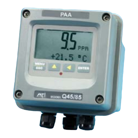
Analytical Technology Q45R User manual

ModelQ45R
2-WireORP Transmitter
HomeOfficeEuropeanOffice
AnalyticalTechnology,Inc.ATI(UK) Limited
6Iron BridgeDriveUnit 1&2GateheadBusiness Park
Collegeville, PA 19426Delph NewRoad, Delph
Saddleworth
Ph:(800)959-0299Ph: 0800-018-4020
(610)917-0991+ 44(0) 1457-873-318
Fax: (610)917-0992Fax: + 44(0) 1457-874-468
Email: sales@analyticaltechnology.com Email:sales@atiuk.com

PRODUCT WARRANTY
AnalyticalTechnology,Inc.(Manufacturer) warrantstothe Customerthatifanypart(s)
ofthe Manufacturer's equipmentprovestobe defectiveinmaterialsorworkmanship
withinthe earlierof18 monthsof the dateof shipmentor12monthsof the dateofstart-
up,suchdefectivepartswillbe repaired orreplacedfreeofcharge.Inspectionand
repairstoproductsthoughttobe defectivewithinthewarrantyperiodwillbe completed
atthe Manufacturer's facilitiesinCollegeville,PA. Productson whichwarrantyrepairs
arerequired shall be shippedfreight prepaidtothe Manufacturer. The product(s)willbe
returnedfreightprepaidandallowed ifitisdeterminedbythe manufacturerthatthe
part(s)failed duetodefectivematerialsorworkmanship.
Thiswarrantydoesnotcoverconsumableitems,batteries,orwearitemssubject
toperiodicreplacement includinglampsandfuses.
Gassensorscarrya12 monthsfromdateofshipmentwarrantyandaresubject
toinspectionforevidenceofmisuse,abuse,alteration,improperstorage,orextended
exposuretoexcessivegasconcentrations.Shouldinspection indicatethatsensors
havefailed duetoanyoftheabove, the warrantyshall notapply.
TheManufacturerassumesnoliabilityforconsequentialdamagesofanykind,
and thebuyerbyacceptanceofthisequipmentwill assumeall liabilityforthe
consequencesofitsuseormisusebythe Customer, hisemployees, orothers. A defect
withinthe meaningofthiswarrantyisanypartofanypieceofaManufacturer's product
whichshall,when suchpartiscapableof beingrenewed,repaired,orreplaced,operate
tocondemnsuchpieceofequipment.
Thiswarrantyisinlieu ofall otherwarranties(includingwithoutlimitingthe
generalityofthe foregoingwarrantiesofmerchantabilityand fitness foraparticular
purpose),guarantees,obligationsorliabilitiesexpressed orimplied bythe Manufacturer
oritsrepresentativesand bystatuteorruleoflaw.
Thiswarrantyisvoidifthe Manufacturer's product(s)hasbeensubjecttomisuse
orabuse,orhasnotbeen operatedorstoredinaccordancewithinstructions,orifthe
serialnumberhasbeenremoved.
AnalyticalTechnology, Inc. makesnootherwarrantyexpressed orimpliedexcept
asstated above.
.

TableofContents
PART1-INTRODUCTION........................................5
1.1 GENERAL (Q45R, ORP MONITOR)................... 5
1.2 FEATURES..................................................... 6
1.3 Q45R SYSTEM SPECIFICATIONS ........................ 6
1.4 Q45R PERFORMANCE SPECIFICATIONS .............. 8
1.5 GENERAL (Q25R, ORP SENSOR)...................... 8
1.6 SENSOR FEATURES ......................................... 8
1.7 SENSOR SPECIFICATIONS.................................. 9
1.8 IMPORTANT NOTES ...................................... 10
PART2–ANALYZER MOUNTING..........................11
2.1 GENERAL.................................................... 11
2.2 WALL OR PIPE MOUNT ................................. 13
PART3–SENSOR/FLOWCELL MOUNTING............15
3.1 GENERAL.................................................... 15
3.2 FLOW TEE MOUNTING.................................. 17
3.3 UNION MOUNTING ...................................... 18
3.4 SUBMERSION MOUNTING.............................. 20
3.5 INSERTION MOUNTING ................................. 21
3.6 CONVENTIONAL ORP SENSORS ...................... 23
3.7 SEALED FLOWCELL ....................................... 25
3.8 FLOW TEE ADAPTER ..................................... 26
3.9 LOCK-N-LOAD SYSTEM.................................. 27
PART4–ELECTRICALINSTALLATION....................28
4.1 GENERAL.................................................... 28
4.2 TWO-WIRE................................................. 28
4.21 LOAD DRIVE................................................ 30
4.3 SENSOR WIRING .......................................... 31
4.4 DIRECT SENSOR CONNECTION ........................ 32
4.5 JUNCTION BOX CONNECTION ......................... 34
4.6 COMBINATION ELECTRODE CONNECTION.......... 35
4.7 EXTERNAL TEMPERATURE COMPENSATION ....... 37
PART5–CONFIGURATION...................................38
5.1 USER INTERFACE.......................................... 38
5.11 KEYS.......................................................... 39
5.12 DISPLAY ..................................................... 39
5.2 SOFTWARE ................................................. 41
5.21 SOFTWARE NAVIGATION............................... 41
5.22 MEASURE MENU [MEASURE]...................... 44
5.23 CALIBRATION MENU [CAL]............................... 45
5.24 CONFIGURATION MENU [CONFIG]................ 46
5.25 CONTROL MENU [CONTROL]....................... 48
5.26 DIAGNOSTICS MENU [DIAG]............................ 49
PART6–CALIBRATION......................................... 53
6.1 OVERVIEWAND METHODS ............................ 53
6.11 SENSOR SLOPE ............................................ 54
6.12 SENSOR OFFSET........................................... 54
6.13 2-POINT CALIBRATION EXPLAINED .................. 54
6.14 1-POINT CALIBRATION EXPLAINED .................. 55
6.2 PERFORMING A 2-POINT CALIBRATION ............ 55
6.3 PERFORMING A 1-POINT CALIBRATION ............ 57
6.4 TEMPERATURE CALIBRATION.......................... 58
PART7–PIDCONTROLLERDETAILS..................... 60
7.1 PID DESCRIPTION ........................................ 60
7.2 PID ALGORITHM.......................................... 60
7.3 CLASSICAL PID TUNING................................. 62
7.4 MANUAL PID OVERRIDE CONTROL ................. 63
7.5 COMMON PID PITFALLS................................ 63
PART8–MAINTENANCEANDTROUBLESHOOTING
............................................................................. 65
8.1 SYSTEM CHECKS .......................................... 65
8.2 INSTRUMENT CHECKS ................................... 66
8.3 DISPLAY MESSAGES...................................... 66
8.4 CLEANING THE SENSOR ................................. 69
8.5 REPLACING THE SALTBRIDGEAND REFERENCE
BUFFER SOLUTION ................................................... 70
8.6 TROUBLESHOOTING...................................... 71
SPAREPARTS........................................................ 73

4
O&M Manual
Rev-U (2/14)
TableofFigures
Figure1-Q45 EnclosureDimensions......................................................................................12
Figure2-Wall orPipe Mount Bracket......................................................................................13
Figure3-Wall Mounting Diagram ............................................................................................14
Figure4- Pipe MountingDiagram............................................................................................14
Figure5-Q25 SensorTypes....................................................................................................16
Figure6- Flow Through Tee Mount..........................................................................................17
Figure7- 1.5"Union Mount......................................................................................................18
Figure8- 2" Union Mount.........................................................................................................19
Figure9- Sensor Submersion Mount.......................................................................................20
Figure10 - S.S.SensorInsertion Mount...................................................................................21
Figure11 - CPVC SensorInsertion Mount................................................................................22
Figure12 -(63-0008) Comb.ORPSensor-Flow.....................................................................23
Figure13 -(63-0023) Combination ORP Sensor- Submersion................................................23
Figure14 - Sealed Flowcell Details...........................................................................................25
Figure15 - Twist-LockTee .......................................................................................................26
Figure16 - Lock-n-Load Sensor Exploded View.......................................................................27
Figure17 - LoopPower Wiring Diagram...................................................................................29
Figure18 - CableDescription, Model Q25................................................................................31
Figure19 - DetachableSingleShielded Cable, Q25R...............................................................32
Figure20 - Sensor CablePreparation.......................................................................................33
Figure21 - Junction BoxInterconnect Wiring............................................................................34
Figure22 - Sensor Connections,Combination Electrodes........................................................35
Figure23 - Combination Electrode Connection.........................................................................36
Figure24 - ExternalTemperatureCompensation Figure..........................................................37
Figure25 - UserInterface.........................................................................................................38
Figure26 - SoftwareMap.........................................................................................................43
Figure27 -Q45H ISA (ideal) Equation......................................................................................61
Figure28 - Replacing theSaltbridge andReference Buffer......................................................70

5
O&M Manual
Rev-U (2/14)
Part 1-Introduction
1.1General (Q45R,ORPMonitor)
TheModelQ45RORPmonitor/analyzerprovidesan extremelyversatile
measurementsystemformonitoringand controlofORP(oxidation/reduction
potential,REDOX)overthe rangeof–1000mVto+2000 mV. Theinstrumentis
offeredstandardasaloop-powered transmitterfor2-wireDC applications.Since
thissystemconfiguration operatesoveronlytwolow-voltagewires,itisidealfor
remotemonitoringapplicationswherelinepoweriseitherunavailableor
prohibitivelyexpensivetorun
Monitorsareavailableinthree electronicversions,aloop-powered 2-wire
transmitter,adual“AA”batteryoperated portableunitwithtwovoltageoutputs,
and a5-17VDC Externallypowered unitwithtwovoltageoutputs.Thismanual
referstotheLoop-Powered 2-wiretransmitterversion.
Inall configurations,theQ45RdisplaysmV,sensortemperature,and outputloop
currenton the secondaryline ofthecustomdisplay.The instrumentmaybe
used witheitherthe highperformanceQ25seriessensorsorwithcombination-
styleelectrodes.
WARNING:Notfollowing operating instructionsmayimpairsafety.

ATI Q45RORPMonitorSystemPart 1-Introduction
6
O&M Manual
Rev-U (2/14)
1.2Features
·StandardQ45Relectronictransmittersaredesigned tobe afullyisolated,
loop powered instrumentsfor2-wireDC applications.
·OutputHold,OutputSimulate,OutputAlarm,and OutputDelayFunctions.
All forcedchangesinoutput condition includebumpless transfertoprovide
gradualreturntoon-line signallevelsand toavoidsystemcontrolshocks
on bothanalogoutputs.
·SelectableOutputFail Alarmfeatureallowssystemdiagnosticfailuresto
be sent toexternalmonitoringsystems.
·Large,highcontrast,customSuper-Twistdisplayprovidesexcellent
readabilityeven inlowlightconditions.The secondaryline ofdisplay
utilizes5x7dotmatrixcharactersforclearmessagedisplaytwooffour
measuredparametersmaybe on the displaysimultaneously.
·Diagnosticmessagesprovide acleardescription ofanyproblemwithno
confusingerrorcodestolookup.Messagesarealsoincluded for
diagnosingcalibrationproblems.
·Quick andeasytwo-pointand samplecalibration methods.Toprovide
highaccuracy,all calibration methodsinclude stabilitymonitorsthatcheck
temperatureand mainparameterstabilitybeforeacceptingdata.
·SelectablePt1000orPt100temperatureinputs.Systemscanalsobe
hard-configuredforthree-wireelements.Temperatureelementcan be
usercalibrated.
·Securitylock featuretopreventunauthorized tamperingwithtransmitter
settings.All settingscan be viewed whilelocked,buttheycannotbe
changed.
1.3Q45RSystemSpecifications
Enclosure NEMA4X,polycarbonate, stainless steelhardware,
weatherproofandcorrosion resistant,
HWD:4.4”(112 mm)× 4.4”(112mm)×3.5”(89 mm)
Mounting Options Wall orpipe mountbracketstandard.Bracketsuitablefor
either 1.5”or2”I.D. U-Boltsfor pipemounting.
Weight 1lb.(0.45kg)

ATI Q45RORPMonitorSystemPart 1-Introduction
7
O&M Manual
Rev-U (2/14)
Display 0.75”(19.1mm) high4-digitmaindisplaywithsign
12-digit secondarydisplay, 0.3"(7.6mm)5x7dotmatrix.
Keypad 4-keymembranetype withtactilefeedback, polycarbonate
withUV coating, integral EMI/staticshieldandconductively
coated window
Ambient Temperature Service, -20 to60°C(-4to140ºF)
Storage,-30to70°C (-22to158 ºF)
Ambient Humidity 0to95%,indoor/outdooruse,non-condensingtorated
ambienttemperaturerange
Altitude Maximum 2000m(6562 Ft.)
ElectricalCertification OrdinaryLocation,cCSAus (CSA and ULstandards -both
approved byCSA), pollution degree 2,installation category
2
EMI/RFIInfluence Designed toEN 61326-1
OutputIsolation 600 Vgalvanicisolation
Filter Adjustable0-9.9minutesadditionaldamping to90%step
input
TemperatureInput SelectablePt1000 or Pt100 RTDwithautomatic
compensation
DisplayedParameters Maininput, -1000 to+2000 mV
Sensortemperature,-10.0to110.0°C (14 to230ºF)
Loop current, 4.00 to20.00 mA
Modelnumberand softwareversion
MainParameterRanges -1000 to+2000 mV
Power 16-35 VDC
Conduit Openings TwoPG-9openingswithgland seals
DC CableType Belden twisted-pair, shielded, 22gaugeor larger

ATI Q45RORPMonitorSystemPart 1-Introduction
8
O&M Manual
Rev-U (2/14)
1.4Q45RPerformanceSpecifications
InputImpedance Greaterthan1013 Ohms
Accuracy 0.1%of span or better(± 2mV)
Repeatability 0.1%of span or better(± 2mV)
Sensitivity 0.05%of span (± 2mV)
Stability 0.05%of span per 24hours,non-cumulative
(±1mV)
Warm-up Time 7secondstorated performance
SupplyVoltageEffects ± 0.05%span
InstrumentResponse 6secondsto90%of stepinput at lowest setting
Time
TemperatureDrift Span or zero, 0.02%of span/°C
Max.Sensor-Instrument 3,000 ft.(914 meters) w/preamp,
Distance 30 ft.(9.1meters) w/opreamp
SensorTypes ModelQ25R ORP w/ preamp- 5wireinput, orcombination
styleORP electrode w/TC- 2wireinput
1.5General (Q25R,ORPSensor)
TheModelQ25RORPSensormeasurestheoxidation/reduction potential(also
knownasREDOX)ofaqueoussolutionsinindustrialandmunicipalprocess
applications.It isdesigned toperformintheharshestofenvironments,including
applicationsthatpoison conventionalORPsensors.All sealsaredualo-ring
usingmultiplesealingmaterials.Thesensorisdesigned forusewiththe Q45R
Monitor/Analyzer.
1.6Sensor Features
·Ahighvolume,dualjunction saltbridgeisutilized tomaximizethe in-
servicelifetimeofthe sensor.The annularjunction providesalarge
surfacearea tominimizethe chanceoffouling.Largeelectrolytevolume
and dualreferencejunctionsminimizecontamination ofthe reference
solution. Thesaltbridgeisreplaceable.
·Thereferenceelementofthe sensorisaglass electrodeimmersed ina
referencebuffersolution.Thisglass referencesystemgreatlyincreases
the rangeofsensorapplications.

ATI Q45RORPMonitorSystemPart 1-Introduction
9
O&M Manual
Rev-U (2/14)
·An integralpreamplifierisencapsulatedinthe bodyofthesensor.This
createsalowimpedancesignaloutputwhichensuresstablereadingsin
noisyenvironmentsand increasesthe maximumpossibledistance
between sensorandtransmitterto3,000feet(914 meters).
·Systemdiagnostics warntheuserinthe eventofelectrode breakage,loss
ofsensorsealintegrityorintegraltemperatureelementfailure.
·Pt1000 RTD.Thetemperatureelementused inATIsensorsishighly
accurateandprovidesahighlylinearoutput.
·TheQ25Risfullysubmersible.
1.7Sensor Specifications
Measuring Range -1000 to+2000 mV
Sensitivity 0.2mV
Stability 2mVper24 hours,non-cumulative
WettedMaterials PEEK, ceramic,titanium, glass,Viton,EDPM
(optional: 316stainless steelwith316SS body)
TemperaturePt1000 RTD
Compensation
SensorCable 6Conductor(5areused)plus 2shields,15 feet(4.6
meters)standardlength
TemperatureRange -5to+95 °C(23to203 °F)
PressureRange 0to100 psig
MaximumFlowRate 10 feet(3meters) per second
Max.Sensor-Analyzer 3,000 feet(3meters)persecond
Distance
SensorBodyOptions 1” NPTconvertible, 1¼” insertion, 1½” or2”sanitary-style
Weight 1lb.(0.45kg)
Notes: 1.The type ofhardwareused tomountthe sensormaylimitthemaximumtemperature
and pressureratings.Please consultthe hardwaremanufacturer’sspecifications to
obtaintherelevanttemperatureandpressurerating information.

ATI Q45RORPMonitorSystemPart 1-Introduction
10
O&M Manual
Rev-U (2/14)
2.The maximumflowratespecification islowerforprocess solutions withlowionic
conductivityorhighsuspended solids concentration.Highflowrates inlowionic
conductivityprocesses maycause ameasurementerrordue tostaticelectrical
discharge.Highflowrates inprocesseswithhighsuspendedsolids concentration
maydecreasethefunctionallifeof thesensor byeroding themetalelectrode.
1.8ImportantNotes
Theglass electrode must bewetted atall timestoensureproper
functionality. Q25Rsensorsareshipped withafluid-filledcapoverthe
electrodetoenableimmediateuse(removecap beforeinstalling,savefor
storageandshippingpurposes).Electrodesthathavedriedoutforany
reason shouldbehydratedfor24hourstorestorefull functionality.
A platinummeasuringelectrodeisstandard. However, DO NOTuse
platinumelectrode inprocess applicationscontainingcadmium(Cd),
nickel(Ni),tin(Sn),orzinc(Zn).Agoldelectrode isavailableforthese
applications.
Likewise, DO NOTuseagoldelectrodeinprocess applicationscontaining
Cyanide (CN-).
NOTE:ThestandardQ25Rprocesselectrodeismadeofmetal
on glassand maybreak ifnothandledproperly. Shouldthe
electrodeeverbreak,USE CAUTIONwhenhandling thesensor
toavoidseriouscuts.
Equipment bearingthismarkingmaynotbe discarded bytraditional
methodsinthe European communityafterAugust 12 2005perEU
Directive2002/96/EC.End usersmust returnoldequipment tothe
manufacturerforproperdisposal.

11
O&M Manual
Rev-U (2/14)
Part 2–AnalyzerMounting
2.1General
All Q45 Seriesinstrumentsoffermaximummountingflexibility.Abracketis
includedwitheachunitthatallowsmountingtowallsorpipes.Inall cases,
choosealocation thatisreadilyaccessibleforcalibrations.Alsoconsiderthatit
maybe necessarytoutilizealocation wheresolutionscanbeused duringthe
calibration process.Totakefull advantageofthe highcontrastdisplay,mount
the instrumentinalocation wherethe displaycan be viewed fromvariousangles
and longdistances.
Locatethe instrumentincloseproximitytothe pointofsensorinstallation -this
will alloweasyaccess duringcalibration.ThestandardcablelengthoftheORP
sensoris15feet. Forsensorcableslongerthan 30 feet,usethe optional
junctionbox(07-0100)and sensorinterconnect cable(31-0057).
Referto Error! Reference source notfound.3 and Figure 1 -Q45 Enclosure Dimensions
4fordetaileddimensionsofeachtype of system.

ATI Q45RORPMonitorSystemPart 3–Sensor/Flowcell Mounting
12
O&M Manual
Rev-U (2/14)
Figure 1 -Q45 EnclosureDimensions
1" NPT
1.23
(31.2)
.82
(20.8)
BOTTOM VIEW
3.45
(87.6)
1.68
(42.7)
SIDE VIEW
4.38
(111.2)
4.38
(111.2)
ENTER
MENU
ESC
FRONTVIEW
2.61
(66.3)
2.61
(66.3)
#10-32 UNF
(4PLACES)
BACK VIEW
PG-9PORT
(2PLACES)
1.23
(31.2)
BOTTOM VIEW

ATI Q45RORPMonitorSystemPart 3–Sensor/Flowcell Mounting
13
O&M Manual
Rev-U (2/14)
2.2Wallor PipeMount
A PVC mounting bracketwith attachment screws is suppliedwith eachtransmitter(see Figure 2 -
Wall orPipeMount Bracket
2fordimensions).The multi-purposebracketisattachedtotherearofthe
enclosureusingthe fourflat headscrews.The instrumentisthen attached tothe
wall usingthe fouroutermountingholesinthe bracket.Theseholesareslotted
toaccommodatetwosizesofu-boltthatmaybe usedtopipemounttheunit.
Slotswill accommodateu-boltsdesigned for1½“or2”pipe.The actualcenterto
centerdimensionsforthe u-boltsareshowninthedrawing.Notethattheseslots
areforu-boltswith¼-20 threads.The 1½”pipe u-bolt(2”I.D.clearance)is
availablefromATI intype 304 stainless steelunderpartnumber(47-0005)
Figure 2 -Wall orPipeMount Bracket

ATI Q45RORPMonitorSystemPart 3–Sensor/Flowcell Mounting
14
O&M Manual
Rev-U (2/14)
ENTER
MENU
ESC
Figure 3 -WallMounting Diagram
ENTER
MENU
ESC
Figure 4 -PipeMounting Diagram

15
O&M Manual
Rev-U (2/14)
Part 3–Sensor/Flowcell Mounting
3.1General
TheQ25RORPSensormountingoptionsinclude flow-through, submersion,
insertion (specialhardwarerequired), orsanitarymount dependingon the type of
sensorpurchased.
Q25RDifferentialORPSensorsareavailablein4differentversionsasshownin
Figure 5 -Q25 SensorTypes
5.The convertiblestyleisthe mostcommon andcanbeused foreitherflow-
throughorsubmersion applications.Aconvertiblesensorwithaquick-
disconnectreceptacleis.Thisversion maynotbesubmerged andshouldnotbe
usedinunprotected outdoorlocations. Forspecialapplications, theQ25Risalso
availableinastainless steelbodiedversion forinsertion type installations,orcan
be suppliedineither1.5”or2”sanitaryversions.

ATI Q45RORPMonitorSystemPart 3–Sensor/Flowcell Mounting
16
O&M Manual
Rev-U (2/14)
Figure 5 -Q25 SensorTypes

ATI Q45RORPMonitorSystemPart 3–Sensor/Flowcell Mounting
17
O&M Manual
Rev-U (2/14)
3.2FlowTee Mounting
Convertiblesensorsmay be usedina 1”flow tee as shown inFigure6 -FlowThrough Tee Mount
.Theflowtee isamodifiedpipefittingthataccommodatesthepipe threadon
the frontofthe sensor.Samplemustflowdirectlyagainstthe faceofthe sensor
asshown.Thesensormaybemountedhorizontallyprovided thatthe outletflow
ispointedup toavoid“air locking”inthe tee.Notethatstandard1”tee fittings
will notworkwithoutmodification due toclearanceproblemsinmostmolded
tees.
Figure 6 -Flow Through Tee Mount

ATI Q45RORPMonitorSystemPart 3–Sensor/Flowcell Mounting
18
O&M Manual
Rev-U (2/14)
3.3Union Mounting
Formountingthe sensorinlargerpipe andallowingforeasysensorremoval, a1
½” of2”union mount adaptersystemisavailable.Thisarrangement allows
connection ofthe sensortopipe sizesupto2inches(usingadaptersif
necessary)whileallowingeasyremovalwithout twistingsensorwires. Contact
ATI forpart numbersand pricesforunion mountassembliesandassociatedpipe
tees.
Figure 7 -1.5"Union Mount
Q45R
SENSOR
1½UNION
1½NIPPLE
1½TEE
(CUSTOMER
SUPPLIED)
1½UNION
1½NIPPLE
1½TEE
(CUSTOMER
SUPPLIED)

ATI Q45RORPMonitorSystemPart 3–Sensor/Flowcell Mounting
19
O&M Manual
Rev-U (2/14)
Figure 8 -2"Union Mount

ATI Q45RORPMonitorSystemPart 3–Sensor/Flowcell Mounting
20
O&M Manual
Rev-U (2/14)
3.4Submersion Mounting
When usingthissensorforsubmersionapplications,mount thesensortothe end
ofa1”mountingpipeusinga1”coupling. ATI’s(00-0628)mountingassembly
showninFigure 9 -SensorSubmersion Mount
9isavailableforsubmersibleapplications. Thisassemblyisdesigned tomount
tostandardhandrailsand facilitatesinsertionand removalof thesensor.
Figure 9 -SensorSubmersion Mount
Table of contents
Other Analytical Technology Transmitter manuals