A1101R09x – Users Manual Page 7 of 26
Release Date 02/10/11
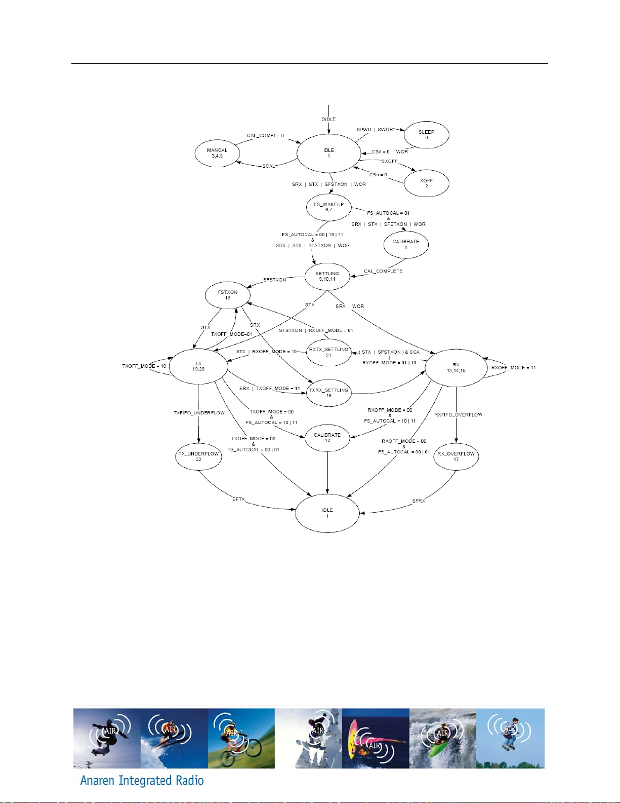
To transmit, a frame of data is placed in the FIFO; this may include a destination address. A
transmit command is given, which will transmit the data according to the initial setup of the
registers. To receive data, a receive command is given, which enables the unit to “listen” for a
transmission; when such a transmission occurs, it places the received frame in the FIFO. When
neither transmit or receive are required, the device can enter either an Idle mode, from which it
can quickly re-enter receive, a transmit mode, or a low power sleep mode from which a crystal
startup is required prior to transmit or receive operation.
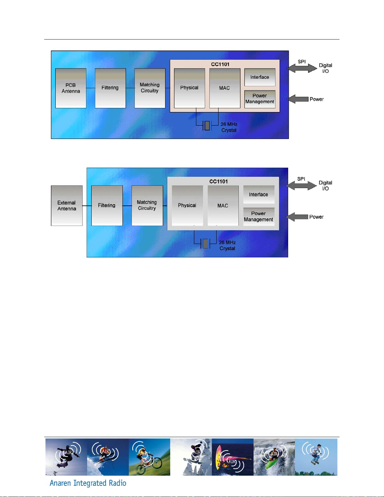
Below is a block diagram for each of the A1101R09A and A1101R09C modules.
•Antenna
oThe antenna couples energy between the air and the AIR module. For
applications where installations are done by an end user (non-professional), an
omni-directional antenna pattern is desired, such that the application will work
equally well in any direction. Similarly for peer to peer or point to multipoint
applications an omni-directional pattern is desired such that all nodes have a fair
chance of communicating. The A1101R09A module has an integral antenna that
is near omni-directional, whereas the A1101R09C has approved antenna options
ranging from near omni-directional to shaped front/back patterns (useful for
inline, professional installations). Note that the end radiation pattern depends not
only on the antenna, but also on the ground plane, enclosure and installation
environment.
•Filtering
oFiltering removes spurious signals to comply with regulatory intentional radiator
requirements.
•Matching
oMatching provides the correct loading of the transmit amplifier to achieve the
highest output power, as well as the correct loading for the receive LNA to
achieve the best sensitivity.
•Physical
oThe physical layer provides conversions between data, symbol and RF signal.
•MAC
oThe MAC layer is part of the Logical Link Layer and provides frame handling,
addressing and medium access services.
•Microcontroller Interface
oThe microcontroller interface exposes registers and commands for the physical
and MAC layers to a microcontroller.
•Power Management
oPower management ensures a stable supply for the internal functions, as well as
providing means for a low power sleep mode (in which case, most of the
transceiver is power off).