AND LCCD20 Series User manual

1WMLCCD20-KR
LCCD20 시리즈
압축형 디지털 로드셀
LCCD20 Series
Compression Digital Load Cell
취급설명서
Instruction Manual
LCCD20T010-K
LCCD20T010N-K
LCCD20T020-K
LCCD20T020N-K
LCCD20T030-K
LCCD20T030N-K
LCCD20T010-KC6
LCCD20T010N-KC6
LCCD20T020-KC6
LCCD20T020N-KC6
LCCD20T030-KC6
LCCD20T030N-KC6

□ LCCD20 시리즈 압축형 디지털 로드셀 일람
LCCD20T010-K (금속 지그 부속 타입, 정격용량 98.07kN(10t), 정밀도 등급 C4)
LCCD20T020-K (금속 지그 부속 타입, 정격용량 196.1kN(20t), 정밀도 등급 C4)
LCCD20T030-K (금속 지그 부속 타입, 정격용량 294.2kN(30t), 정밀도 등급 C4)
LCCD20T010-KC6 (금속 지그 부속 타입, 정격용량 98.07kN(10t), 정밀도 등급 C6)
LCCD20T020-KC6 (금속 지그 부속 타입, 정격용량 196.1kN(20t), 정밀도 등급 C6)
LCCD20T030-KC6 (금속 지그 부속 타입, 정격용량 294.2kN(30t), 정밀도 등급 C6)
LCCD20T010N-K (금속 지그 없는 타입, 정격용량 98.07kN(10t), 정밀도 등급 C4)
LCCD20T020N-K (금속 지그 없는 타입, 정격용량 196.1kN(20t), 정밀도 등급 C4)
LCCD20T030N-K (금속 지그 없는 타입, 정격용량 294.2kN(30t), 정밀도 등급 C4)
LCCD20T010N-KC6 (금속 지그 없는 타입, 정격용량 98.07kN(10t), 정밀도 등급 C6)
LCCD20T020N-KC6 (금속 지그 없는 타입, 정격용량 196.1kN(20t), 정밀도 등급 C6)
LCCD20T030N-KC6 (금속 지그 없는 타입, 정격용량 294.2kN(30t), 정밀도 등급 C6)
□ 사용상 주의 사항
본 제품을 올바르고 안전하게 사용하기 위해서 다음과 같은 사항을 주의해 주세요. 여기에 기재된
내용은 기기의 안전한 취급의 주요 사항을 정리한 것입니다. 기기 특유의 주의 사항에 대해서는 이
후의 본문 중에도 기재되어 있으므로 사용 전에 본 설명서를 읽어 주세요.
시공에 필요한 조건
∙ 로드셀를 장착하는 구조물의 강도는 하중을 충분히 견딜 수 있도록 설계해 주세요.
∙ 기초 Base Plate는 평면이면서 수평으로 설치해 주세요.
Base Plate 상호 간의 수평도 : 3 mm이내 (기준)
Base Plate의 수평도 : 1/500이내 (기준)
∙ 피트 내에 로드셀을 설치할 경우, 물이 고이지 않도록 배수 대책을 세워 주세요.
로드셀이 오랫동안 침수되어 있는 경우 고장의 원인이 됩니다.
바닥에 흐름 경사를 지게 한다. (1/100이상)
배수관, 배수통, 배수펌프를 갖춘다.
∙ 요동 제한을 위한 흔들림 방지 Stopper를 반드시 달아 주세요. Stopper의 틈새는 5 mm이하로 해
주세요. 권장은 2~3 mm입니다.
∙ 로드셀을 야외에 설치하는 경우는 직사광선이나 비바람이 직접 닿지 않도록 보호 대책을 세워 주
세요.
시공 상 주의
∙ 로드셀의 기초가 되는 부분은 하중을 지탱하는 중요한 곳이므로 시공 시, 반드시 꼼꼼하게 시공해
주세요.
∙ 로드셀 케이블은 땅겨지지 않게 여유 있게 설치해 주세요. 또 파손되지 않도록 전선관 등에 따른
보호를 해 주세요. 또한 전선관의 동력선과 공용으로 사용하지 마세요.
∙ 로드셀 머리와 설치 금속 지그의 접촉면에는 윤활, 방청을 위한 그리스를 도포해 주세요.
∙ 도포하는 그리스는 리튬 그리스 (만능형 그리스)를 사용해 주세요.
∙ 로드셀 케이블 배선이 잘못되지 않도록 주의해 주세요. 배선의 잘못으로 기기의 손상을 초래할 수
있습니다.
∙ 통전되어 있는 기기에 로드셀의 접속은 하지 마세요. 또 통전 전에 접속에 문제가 없는지 확인해
주세요.
∙ 로드셀에 강한 충격을 주지 마세요.
∙ 최대 인가 전압을 초과하는 전압을 로드셀에 인가하지 마세요. 로드셀 내부를 파손할 우려가 있습
니다.
∙ 로드 셀과 설치 금속 지그의 접촉면에 먼지, 흙 등이 들어가지 않도록 주의해 주세요.
∙ 로드셀을 장착한 채 용접 작업을 할 때는 로드셀에 전류가 흘러가지 않도록 반드시 용접 부분의
근처에 어스를 접속해 주세요.
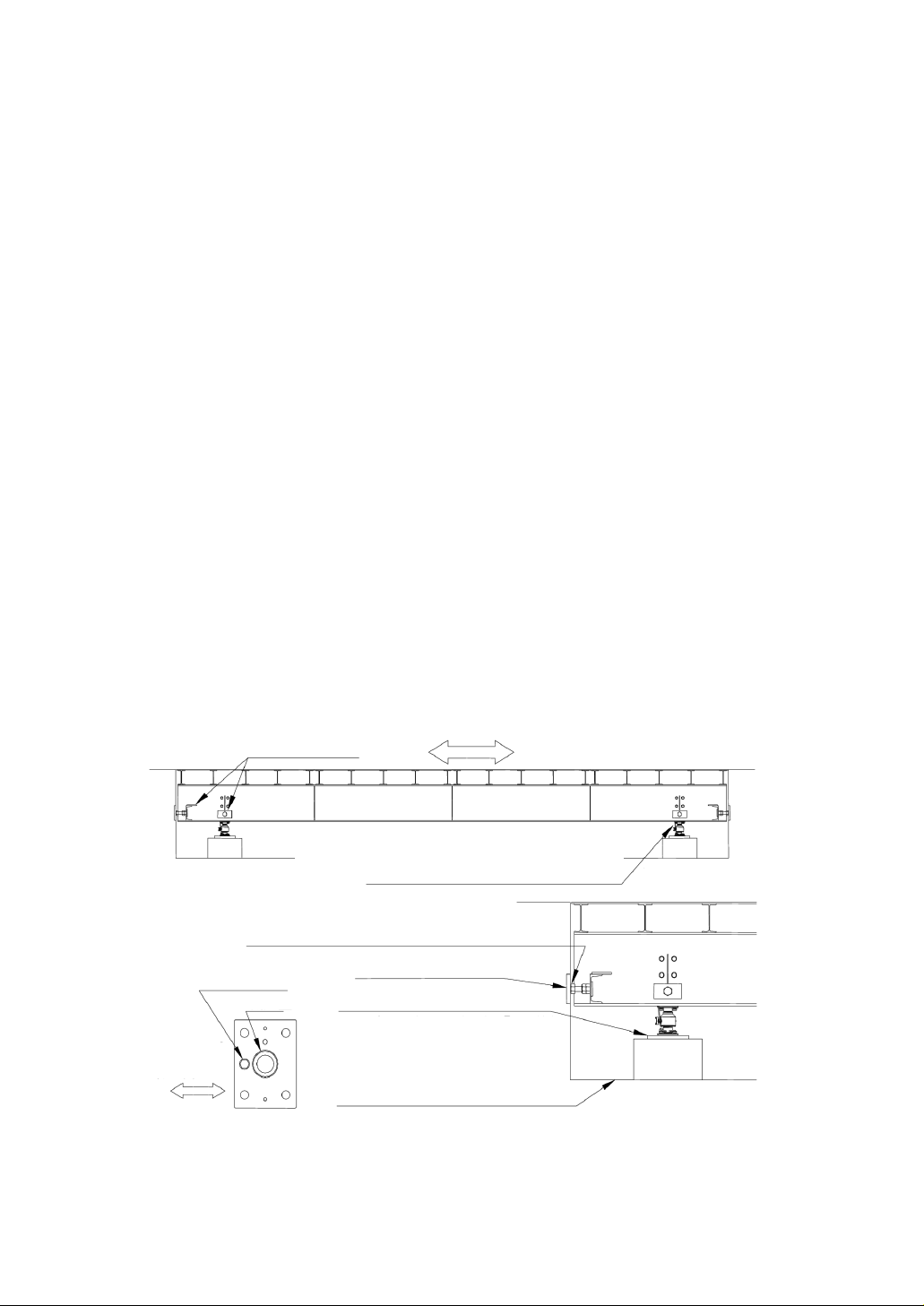
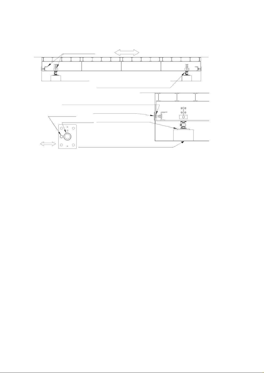
트럭스케일의 설치 예
기초 시공은 꼼꼼하게 시공할 것 !!!
Truck 진행방향
흔들림 방지 Stopper
로드셀 케이블은 전선관으로 보호 해 주세요.
기초 공사는 꼼꼼하게
흔들림 방지 Stopper의 틈새는 5mm이하로 주세요.
권장은 2~3mm
Stopper 보강판
Stopper 기둥
내압판
Base Plate
지면에는 흐름 경사를 지게 한다(1/100이상)
Base Plate 상호 간의 수평도 : 3㎜이내
Base Plate의 수평도 : 1/500이내
Truck
진행방향

설치 작업 상 주의
∙ 로드셀의 방향과 금속 지그의 방향은 본 설명서를 읽고 올바르게 설치해 주세요.
∙ 사용하는 공구와 기구에 불량이 없는지를 확인한 후에 작업을 해 주세요. 파손이 있는 불량의 공
구, 기구를 사용하면 중대한 사고를 초래할 수 있습니다.
∙ 안전 헬멧, 안전화를 신고 작업을 해 주세요.
∙ 로드셀에 받침대 등의 구조물을 올릴 때는 안전을 확인하면서 천천히 올려 주세요.
손가락 등이 끼지 않도록 충분히 주의하시기 바랍니다. 이상을 느낄 때는 작업을 일시 중단하고
안전을 확인한 후에 작업을 재개해 주세요.
일상 점검
다음 항목에 대해서 적절하게 점검하세요.
∙ 흔들림 방지 Stopper의 틈새는 적정한가? 먼지, 흙 등은 묻지 않았는가?
∙ 피트에 물이 고여 있지는 않는가? (로드셀을 피트 안에 설치하는 경우)
∙ 로드셀, 설치 금속 지그에 부착물은 없는가?
∙ 장착 볼트에 느슨한 것은 없는가?
∙ Stopper 기둥에 느슨함은 없는가?
∙ 로드셀 케이블이 타이트하지 않고, 여유는 있는가?
∙ 케이블의 접속에 느슨함은 없는가?
∙ 누전은 없는가?
□ 개요
∙ LCCD20 시리즈 압축형 디지털 로드셀은 트럭 스케일에 적합한 98.07kN(10t)~294.2kN(30t)의 정격
용량을 가진 고성능의 압축형 더블 콘벡스(Double Convex)타입의 디지털 로드셀입니다.
∙ 폐사의 디지털 로드셀 용 인디케이터와의 조합으로 조정 작업을 간단하고 빠르게 진행 수 있습니다.
∙ 로드셀 본체는 밀폐 구조로 보호 등급은 IP68이며 가혹한 환경에서도 안심하고 사용할 수 있습니다.
∙ 소형으로 설계되어 설치, 유지 관리 작업이 편리하게 실시할 수 있습니다.
※ 주의
로드셀은 정밀도와 응답성이 뛰어난 만큼, 설치하는 기기의 구조 및 설치 방법에 주의가 필요합니다.
따라서 성능을 충분히 내기 위해서는 이 설명서를 이해하고, 올바른 설치를 부탁드립니다.

□ 사양
LCCD20T010-K
LCCD20T010N-K
LCCD20T020-K
LCCD20T020N-K
LCCD20T030-K
LCCD20T030N-K
LCCD20T010-KC6
LCCD20T010N-KC6
LCCD20T020-KC6
LCCD20T020N-KC6
LCCD20T030-KC6
LCCD20T030N-KC6
OIML R60에 근거한
정밀도 등급
C4
C6
최대 용량 ( Emax )
10t
20t
30t
10t
20t
30t
최소 로드셀
검정눈금 ( Vmin )
1kg
2kg
3kg
1kg
2kg
3kg
정격 용량
98.07kN(10t)
196.1kN(20t)
294.2kN(30t)
98.07kN(10t)
196.1kN(20t)
294.2kN(30t)
정격 출력
10000±5
20000±10
30000±15
10000±5
20000±10
30000±15
총합 오차
0.025%R.O.
0.016%R.O.
허용 과부하
150%R.C.
온도 보상 범위
-10℃~+40℃
권장 인가 전압
8VDC
최대 인가 전압
12VDC
영점 온도 영향
0.019%R.O. / 10℃ Typ.
출력 온도 영향
0.010%Load / 10℃ Typ.
출력 신호
RS-485 2 선식
케이블 두께/길이
4 심 실드 케이블 φ8 / 12m
보호 등급
IP68(수심 1.5m / 100시간)
낙뢰 대책
가스 튜브 어레스터 등 내장
무게
약 11kg (장착 금속 지그 포함) 약 5kg (로드셀 본체)
로드셀 케이블의 심선의 색과 접속의 대응은 다음과 같습니다.
※ 배선이 잘못되지 않도록 충분히 주의하시기 바랍니다.
빨강…전원 + 녹색…데이터 +
흰색…전원 - 파랑…데이터 -
노랑…실드
∙ 데이터 극성은 정논리를 +, 부논리를 –로 한다.

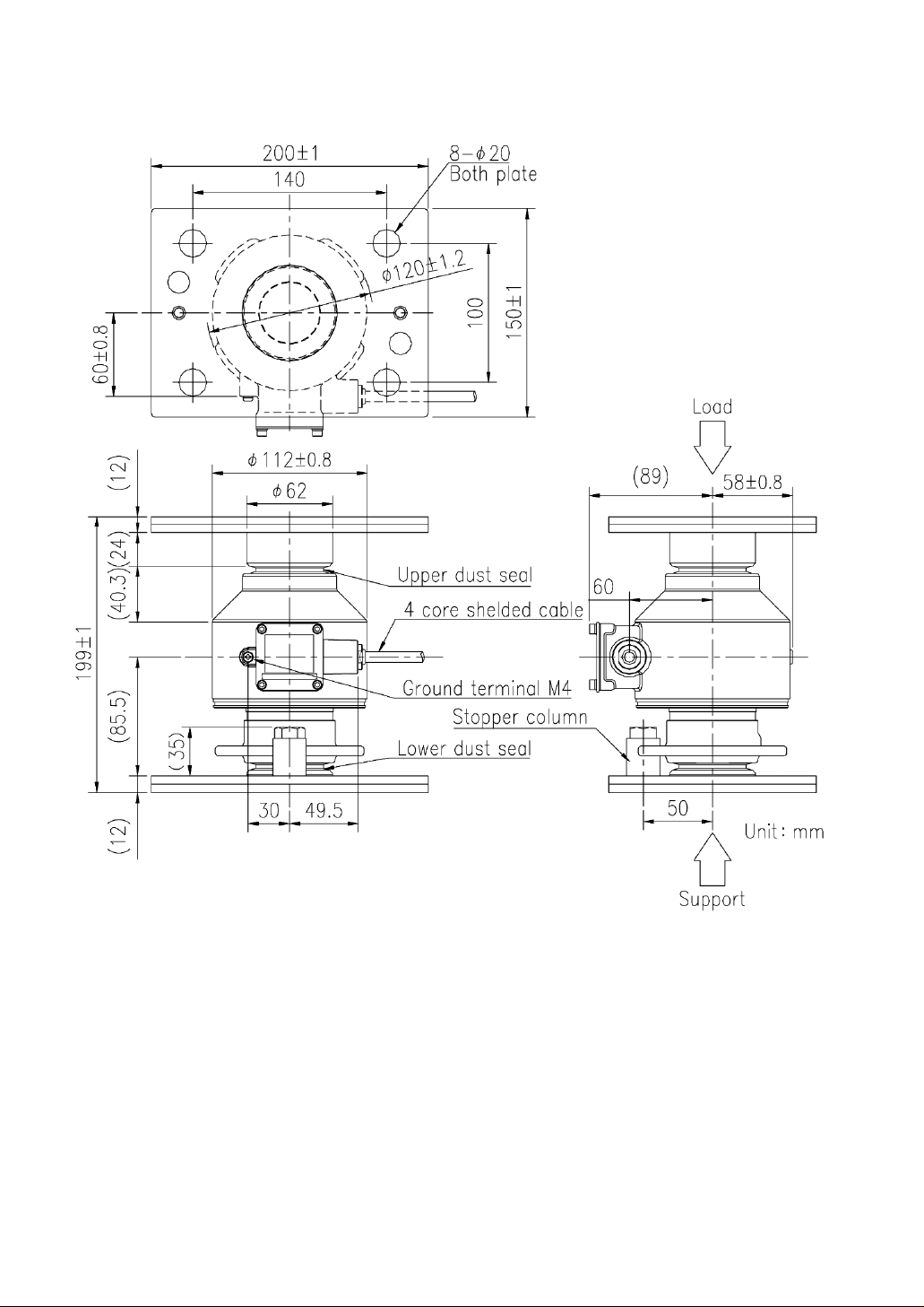
□ 외관도
상하공통
부하
지지
단위 mm
상측 Dust Seal
하측 Dust Seal
4심 실드 케이블
어스 단자 M4
Stopper 기둥

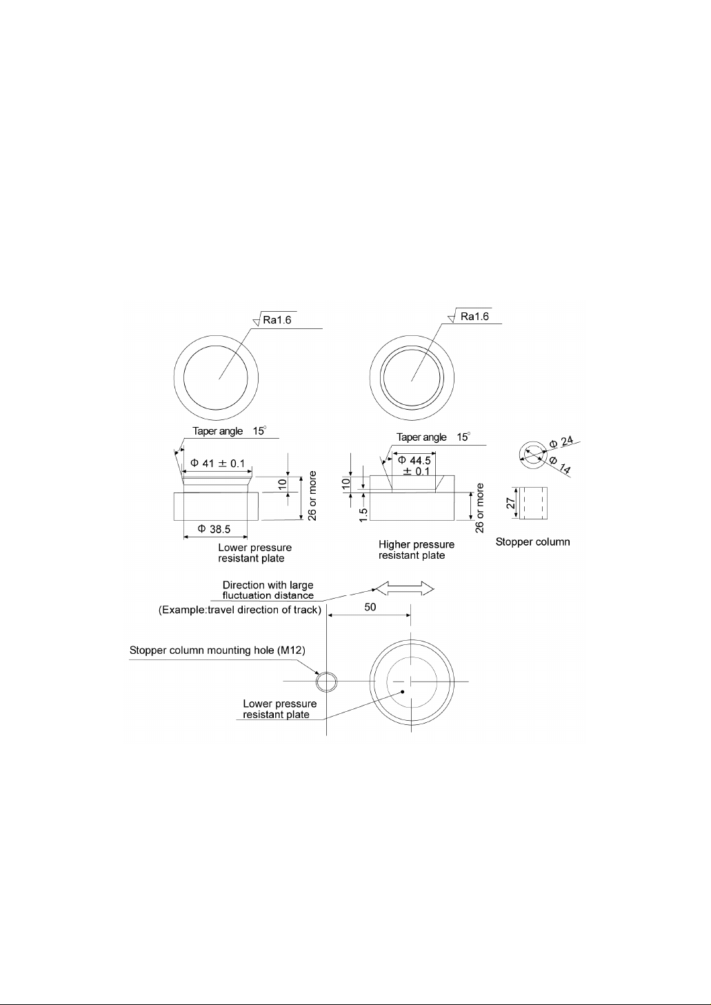
□ 설치 금속지그에 대하여
설치 금속 지그를 제작하는 경우에는 하중을 받은 압력판의 가이드 구멍과 Stopper 기둥을 아래의
그림에 표시되어 있는 치수로 제작 바랍니다. 압력판, Stopper 기둥의 강도는 HRC32~38로 해 주세요.
또 Stopper의 장착에 사용하는 고정용 볼트는 다음과 같습니다.
고정용 볼트 : M12 육각 볼트 (강도 구분 : 10.9)
권장 조임 토크 : 76Nm
Stopper 기둥의 장착 위치는 아래의 그림을 참고로 중심으로 부터 50mm의 위치에 설치 해 주세요.
Taper 각도 15°
Taper 각도 15°
26
이
상
26
이
상
하부 내압판
상부 내압판
Stopper 기둥
요동 거리가 큰 방향
(예 : Truck 진행방향)
Stopper 기둥 장착 구멍 (M12)
하부측 내압판
□ 설치 방법
금속 지그 부속 타입을 기준으로 기재하고 있습니다만, 금속 지그 없는 타입도 이 설치 방법을 참고
로하여 설치해 주세요.
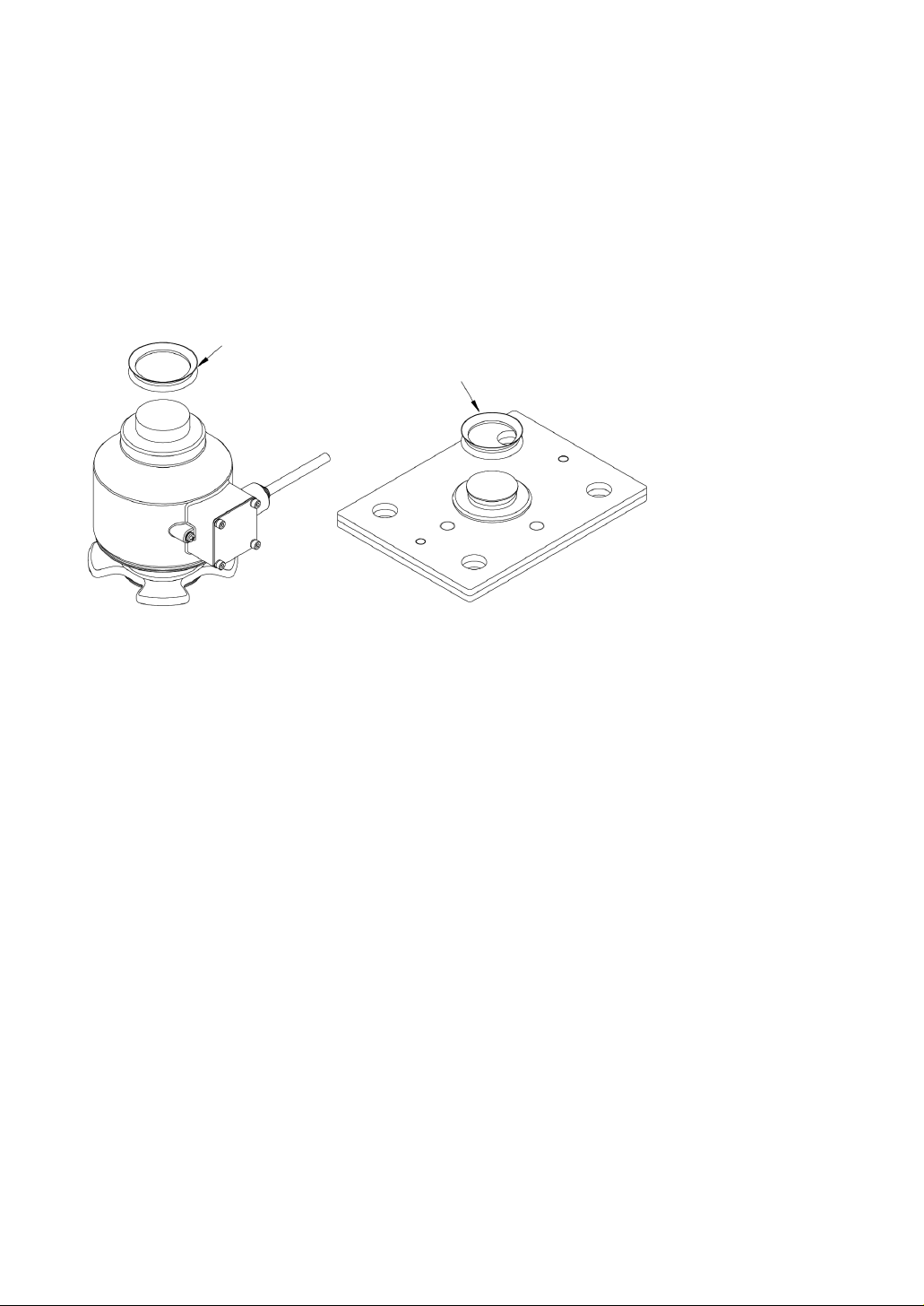
순서 ①
로드셀 상부에 Dust Seal(위쪽)를 끼웁니다.
설치 금속 지그(아래)에 Dust Seal(아래쪽)를 끼웁니다.
내경이 큰 쪽이 로드셀 측의 Dust Seal
내경이 작은 쪽이 금속기구 측의 Dust Seal

순서 ②
설치 금속 지그(아래)를 미리 설치 할 때와 같은 방향에 맞추어 Stopper 기둥을 요동거리가 큰 방향
에 있는 장착 구멍에 부속 M12 육각 볼트로 장착 해 주세요.
예를 들면 트럭 스케일에서는 차량의 진행 방향에 맞추어 주세요.
Stopper 기둥 설치에 사용하는 볼트의 권장 조임 토크는 다음과 같습니다. 참고하세요.
M12 육각 볼트 : 76Nm
고정용 육각 볼트
Stopper 기둥
Stopper 기둥 설치 구멍
요동 거리가 큰 방향
요동 거리가 큰 방향으로 같
은 방향에 있는 구멍 위치에
부착한다.
순서 ③
그림을 참고로 하여, 설치 금속 지그(아래)를 Base Plate에, 설치 금속 지그(위)를 대들보에 각각 시
침질 해 주십시오.
시침질에는 M16 볼트와 스프링 와셔를 사용 해 주세요.
설치 금속 지그의 방향은 설치 전에 미리 설치 할 때와 같은 방향으로 맞춥니다.
요동 거리가 큰 방향
대들보
Stopper 기둥
Base Plate
설치 금속틀
설치 금속틀
M16 볼트와
스프링 와셔

순서 ④
로드셀을 설치 금속 지그(아래)의 위에 설치 해 주세요. 로드셀의 설치에 관해서는 케이블의 방향을
요동거리가 큰 방향에 대하여 직각 방향으로 가지런히 합니다.
예를 들면 트럭 스케일에서는 차량의 진행 방향에 대한 직각 방향이 되도록 맞추어 주세요.
요동 거리가 큰 방향
대들보
Stopper 기둥
Base Plate
설치 금속틀
로드셀
설치 금속틀
순서 ⑤
설치 금속 지그와 로드셀의 위치를 확인하면서 대들보를 서서히 내려 주세요.
순서 ⑥
설치 금속 지그가 로드셀에 가볍게 놓이면 로드셀이 수직이 되도록 설치 금속 지그의 위치를 조정
합니다. 수직은 다른 2방향이 90도 인지 확인 해 주세요. 로드셀의 기울기 각도가 0.5°이하가 되도
록 아래쪽, 위쪽 어느 곳이든 설치 금속 지그의 위치를 미세 조정합니다.
M16 볼트와
스프링 와셔
측면
정면
순서 ⑦
로드셀(설치 금속 지그)의 위치가 정해지면 대들보를 완전히 내리고, 장착 볼트를 조입니다.
M16 볼트의 권장 조임 토크는 다음과 같습니다. 참고하세요.
보통 볼트 사용 시 : 100Nm
고 인장 볼트 사용 시 : 200Nm
순서 ⑧
본 로드셀에는 서지 보호용 접지 스트랩이 2점이 준비되어 있습니다.
로드셀의 설치가 완료되면 각각 그림을 참고하여 어스 스트랩을 달아 주세요.
어스 스트랩의 고정에 사용하는 볼트의 권장 조임 토크는 다음과 같습니다. 참고하세요.
CAP 볼트 (M8) : 12.5Nm
십자 구멍 부착 냄비 머리 작은 나사 (M4) : 1.5Nm
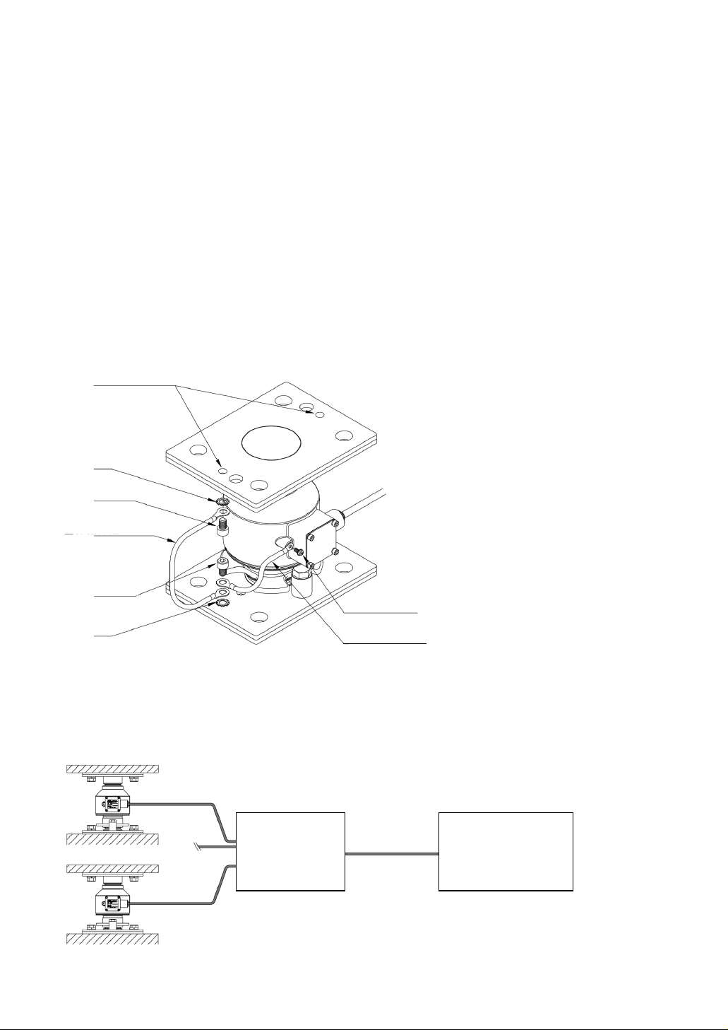
어스 스트랩 설치
상하 공통
클립 와셔
CAP 볼트
M8×12
어스 스트랩
□5.5×20cm
CAP 볼트
M8×12
어스 스트랩
□5.5×30cm
클립 와셔
십자 구멍 부착 냄비 머리 작은나사
M4×12
□ 주요 시스템의 예
로드셀
케이블
AX-KO3217
최대연장 200m
접속함
AD-4388-4
또는
AD-4388-6
디지털 로드셀 용
지시기
AD-4351,
AD-4329A-DLC등

LCCD20 series compression digital load cell
□ LCCD20 series compression digital load cell list
LCCD20T010-K (Type with accessories, Rated capacity 98.07kN(10t), Accuracy class C4)
LCCD20T020-K (Type with accessories, Rated capacity 196.1kN(20t), Accuracy class C4)
LCCD20T030-K (Type with accessories, Rated capacity 294.2kN(30t), Accuracy class C4)
LCCD20T010-KC6 (Type with accessories, Rated capacity 98.07kN(10t), Accuracy class C6)
LCCD20T020-KC6 (Type with accessories, Rated capacity 196.1kN(20t), Accuracy class C6)
LCCD20T030-KC6 (Type with accessories, Rated capacity 294.2kN(30t), Accuracy class C6)
LCCD20T010N-K (Type without accessories, Rated capacity 98.07kN(10t), Accuracy class C4)
LCCD20T020N-K (Type without accessories, Rated capacity 196.1kN(20t), Accuracy class C4)
LCCD20T030N-K (Type without accessories, Rated capacity 294.2kN(30t), Accuracy class C4)
LCCD20T010N-KC6 (Type without accessories, Rated capacity 98.07kN(10t), Accuracy class C6)
LCCD20T020N-KC6 (Type without accessories, Rated capacity 196.1kN(20t), Accuracy class C6)
LCCD20T030N-KC6 (Type without accessories, Rated capacity 294.2kN(30t), Accuracy class C6)
□ Caution
Please read the following notes carefully in order to use this product correctly and safely.
The contents described here summarize the main matters regarding safe handling of equipment.
Notes specific to individual equipment are, it is also described in the following text, so please read
this document before use.
Requirements for construction
∙ The strength of the structure to which the load cell is attached should be designed to sufficiently
withstand the load.
∙ Place base plates flat and level.
Levelness between base plates: within 3mm (approximate)
Levelness of base plate alone: within 1/500 (approximate)
∙ When installing a load cell in a pit, please take countermeasures against drainage so that water
does not accumulate.
∙ If the load cell remains flooded for a long period of time, that may cause a malfunction.
Add a flow gradient on the bottom (1/100 or more)
Equip with a drain pipe, a drain sump and a drain pump.

∙ Be sure to install a steady stopper to restrict sway. The gap of the stopper should be 5 mm or less.
The recommended gap is 2 to 3 mm.
∙ When installing the load cell outdoors, please take measures to protect against direct sunlight or
direct wind and rain exposure.
Precautions for construction
∙ The base part of the load cell is an important part that supports the load.
So please perform construction carefully.
∙ Let the load cell cable have slack so as not to stretch. Also protect with a conduit, etc. to prevent
damage. however, do not use the load cell cable as the power line of the conduit.
∙ Please apply grease to the contact surface between the load cell head and the mounting bracket
for lubrication and corrosion proofing.
∙ Please use lithium grease (all-purpose type grease) for the grease to be applied.
∙ Please be careful not to miswire the load cell cable. Miswiring may damage the equipment.
∙ Please do not connect the load cell to energized equipment. Also make sure that there is no error
in connection before energizing.
∙ Please do not apply a strong shock to the load cell.
∙ Please do not provide voltage exceeding the maximum applied voltage to the load cell. The inside
of the load cell may be damaged if that is done.
∙ Please be careful not to get dirt, mud, etc. on the contact surface between the load cell and the
mounting bracket.
∙ When performing welding work with the load cell attached, please connect the ground to the
welding point so that no current flows in the load cell.
Setup example for truck scale
Construction of the foundation should be done carefully.
Swing stopper
The gap of the swing stopper should be 5 mm or less.
2 to 3mm is recommended.
Direction of truck travel
Protect the load cell cable with a conduct
Be careful in construction of
the foundation
Reinforcing plate stopper
Base plate
Stopper column
Pressure resistant plate
Direction
of truck
travel
Levelness betwenn base plates
: within 3mm
levelness of the base plate alone
: within 1/500
Apply a flow gradient to the bottom (1/100 or more)
Precautions for installation
∙ Please read this manual and correctly set the direction of the load cell and the direction of the
bracket.
∙ Please confirm that there are no problems with the tools and instruments to be used before
performing work.
Continued use of damaged or defective tools and equipment may cause serious accidents.
∙ Please work while wearing a helmet and safety shoes.
∙ When placing a structure such as a truck scale on the load cell, please place it slowly while
checking safety.
Please be careful not to pinch your fingers.
If you sense any problems, please suspend work temporarily and confirm safety before restarting
work.

Maintenance
Please check the following items properly.
∙ Is the gap of the swing stopper appropriate? Is it free of clogging from dirt, mud, etc?
∙ Is the pit free of water? (When installing the load cell in the pit)
∙ Is the load cell and mounting bracket free of deposits?
∙ Is the mounting bolt tight?
∙ Is the stopper column free of slack?
∙ Is there slack in the load cell cable?
∙ Are cable connections tight?
∙ Is the equipment free of electric leakage?
□ Introduction
∙ The LCCD20 series compression type digital load cell is a high performance compression type
double convex type digital load cell with rated capacity of 98.07kN (10t) to 294.2kN (30t) suitable
for truck scales.
∙ Adjustment work can be done easily and quickly by combining with our indicator for digital load
cells.
∙ Since the load cells body has a sealed structure, it is adaptable to harsh environments equivalent
to IP68.
※ Caution
Because the load cell has excellent accuracy and responsiveness, consideration is required for the
structure and installation method of the equipment to be installed. Please understand the contents
of this manual in order to gain maximum performance, and install correctly.
□ Specifications
LCCD20T010-K
LCCD20T010N-K
LCCD20T020-K
LCCD20T020N-K
LCCD20T030-K
LCCD20T030N-K
LCCD20T010-KC6
LCCD20T010N-KC6
LCCD20T020-KC6
LCCD20T020N-KC6
LCCD20T030-KC6
LCCD20T030N-KC6
Accuracy class
according OIML
R60
C4
C6
Maximum capacity
( Emax )
10t
20t
30t
10t
20t
30t
Minimum load cell
verification
interval ( Vmin )
1kg
2kg
3kg
1kg
2kg
3kg
Rated Capacities
98.07kN(10t)
196.1kN(20t)
294.2kN(30t)
98.07kN(10t)
196.1kN(20t)
294.2kN(30t)
Rated Output
10000±5
20000±10
30000±15
10000±5
20000±10
30000±15
Combined error
0.025%R.O.
0.016%R.O.
Safe overload limit
150%R.C.
Compensated
temperature range
-10℃~+40℃
Recommended
excitation voltage
8VDC
Maximum
excitation voltage
12VDC
Temp.
coefficient
zero
0.019%R.O. / 10℃ Typ.
SPAN
0.010%Load / 10℃ Typ.
Output signal
RS-485 2 wire type
Cable
thickness/length
4 core shielded cable φ8 / 12m
Protection class
IP68(Depth of water 1.5m / 100h)
Surge
countermeasure
Built-in gas tube arrester etc.
Mass
Approx.11kg (including mounting bracket) Approx.6kg (load cell body)
The correspondence between the color of the core wire of the load cell cable and the connection is
as follows.
※ Be careful of miswiring.
Red…Power + Green…Data +
White…Power - Blue…Data -
Yellow…Shield
∙ The polarity of data is assumed to be "+" for positive logic and "-" for negative logic.
□ Dimensions
□ About the mounting bracket
When manufacturing the mounting bracket, please make the guide hole and the stopper column of
the pressure resistant plate to which load is applied be of the dimensions shown on the next page.
The hardness of the pressure resistant plate and stopper column should be HRC 32~38.
Also, the fastening bolts used for mounting the stopper is as follows.
Fastening bolt : Hexagon bolt of M12 (Intensity classification:10.9)
Recommended tightening torque : 76Nm
Please attach the stopper column at a position 50mm from the center referring to the figure on the
next page.

□ Attaching the load cell
Although the description if for the type with brackets, please install the type with no brackets as well
referring to the method shown here.
Procedure 1
Fit the dust seal (upper) onto the upper part of the load cell.
Fit the dust seal (lower) onto the mounting bracket (bottom).

Procedure 2
Align the mounting bracket (bottom) in the same direction as before installation, and then attach
the stopper column with the M12 hexagon bolt to the mounting hole.
On a truck scale, for example, please adjust so that it is level with the direction of travel of the
vehicle.
Recommended tightening torque of the bolt used for mounting the stopper column is as follows.
Please use this for reference.
Hexagon bolt of M12:76Nm
Procedure 3
Temporarily fix the mounting bracket (lower) to the base plate and the mounting bracket (upper) to
the main girder respectively. referring to the figure as below.
Please use M16 bolts and spring washers to temporarily fix the components. Align the direction of
the mounting bracket in the same direction as at installation before mounting.
Other manuals for LCCD20 Series
1
This manual suits for next models
12
Table of contents
Languages:


