Fastech Ezi-Step Mini User manual

Operating Manual
www.fastech-motions.com

www.fastech-motions.com - 2
●
●
●
●
●
●
●
●
●
●
●
●
●
●
●
●
●
●
●
●
●
●
●
●
●
●
●
●
●
●
●
●
●
●
●
●
●
●
●
●
●
●
●
●
●
●
●
●
●
●
●
●
●
●
●
●
●
●
●
●
●
●
●
●
●
●
●
●
●
●
●
●
●
●
●
●
●
●
●
●
●
●
●
●
●
●
●
●
●
●
●
●
●
●
●
●
●
●
●
●
●
●
●
●
●
●
●
●
●
●
●
●
●
●
●
●
●
●
●
●
●
●
●
●
●
●
●
●
●
●
●
●
●
●
●
●
●
●
●
●
●
●
●
●
●
●
●
●
●
●
●
●
●
●
●
●
●
●
●
●
●
●
●
●
●
●
●
●
●
●
●
●
●
●
●
●
●
●
●
●
●
●
●
●
●
●
●
●
●
●
●
●
●
●
●
●
●
●
●
●
●
●
●
●
●
●
●
●
●
●
●
●
●
●
●
●
●
●
●
●
●
●
●
●
●
●
●
●
●
●
●
●
●
●
●
●
●
●
●
●
●
●
●
●
●
●
●
●
●
●
●
●
●
●
●
●
●
●
●
●
●
●
●
●
●
●
●
●
●
●
●
●
●
●
●
●
●
●
●
●
●
●
●
●
●
●
●
●
●
●
●
●
●
●
●
●
●
●
●
●
●
●
●
●
●
●
●
●
●
●
●
●
●
●
●
●
●
●
●
●
●
●
●
●
●
●
●
●
●
●
●
●
●
●
●
●
●
●
●
●
●
●
●
●
●
●
●
●
●
●
●
●
●
●
●
●
●
●
●
●
●
●
●
●
●
●
●
●
●
●
●
●
●
●
●
●
●
●
●
●
●
●
●
●
●
●
●
●
●
●
●
●
●
●
●
●
●
●
●
●
●
●
●
●
●
●
●
●
●
●
●
●
●
●
●
●
●
●
●
●
●
●
●
●
●
●
●
●
●
●
●
●
●
●
●
●
●
●
●
●
●
●
●
●
●
●
●
●
●
●
●
●
●
●
●
●
●
●
●
●
●
●
●
●
●
●
●
●
●
●
●
●
●
●
●
●
●
●
●
●
●
●
●
●
●
●
●
●
●
●
●
●
●
●
●
●
●
●
●
●
●
●
●
●
●
●
●
●
●
●
●
●
●
●
●
●
●
●
●
●
●
●
●
●
●
●
●
●
●
●
●
●
●
●
●
●
●
●
●
●
●
●
●
●
●
●
●
●
●
●
●
●
●
●
●
●
●
●
●
●
●
●
●
●
●
●
●
●
●
●
●
●
●
●
●
●
●
●
●
●
●
●
●
●
●
●
●
●
●
●
●
●
●
●
●
●
●
●
●
●
●
●
●
●
●
●
●
●
●
●
●
●
●
●
●
●
●
●
●
●
●
●
●
●
●
●
●
●
●
●
●
●
●
●
●
●
●
●
●
●
●
●
●
●
●
●
●
●
●
●
●
●
●
●
●
●
●
●
●
●
●
●
●
●
●
●
●
●
●
●
●
●
●
●
●
●
●
●
●
●
●
●
●
●
●
●
●
●
●
●
●
●
●
●
●
●
●
●
●
●
●
●
●
●
●
●
●
●
●
●
●
●
●
●
●
●
●
●
●
●
●
●
●
●
●
●
●
●
●
●
●
●
●
●
●
●
●
●
●
●
●
●
●
●
●
●
●
●
●
●
●
●
●
●
●
●
●
●
●
●
●
●
●
●
●
●
●
●
●
●
●
●
●
●
●
●
●
●
●
●
●
●
●
●
●
●
●
●
●
●
●
●
●
●
●
●
●
●
●
●
●
●
●
●
●
●
●
●
●
●
●
●
●
●
●
●
●
●
●
●
●
●
●
●
●
●
●
●
●
●
●
●
●
●
●
●
3
6
7
7
7
8
8
9
9
10
11
11
12
12
12
13
13
13
13
13
14
14
15
16
17
18
Table of Contents
1. Precautions
2. Main characteristics
3. Ezi-STEP MINI Part Numbering
4. Standard Combination
5. Combination with Brake
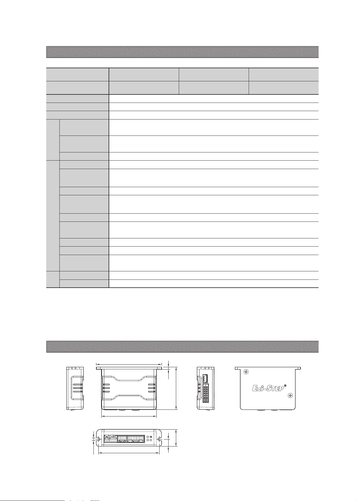
6. Specifications of Drive
7. Dimensions of Drive [mm]
8. Specifications of Motor
9. Torque Characteristics of Motor
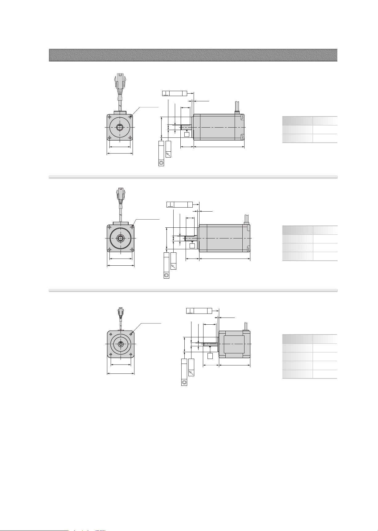
10. Dimensions of Motor [mm]
11. Notes on Installation
12. Settings and Operation
12.1 Drive Status LED
12.2 Stop Current Setting Switch(SW1.1~1.4)
12.3 Resolution Setting Switch(SW1.5~1.8)
12.4 Rotational Direction Setting Switch(SW2.5)
12.5 Pulse Input Setting Switch(SW2.6)
12.6 Signal Connector(CN1)
12.7 Motor Connector(CN3)
12.8 Power Connector(CN4)
13. System Configuration
13.1 Options
13.2 Connector Specifications
14. External Wiring Diagram
15. Control Signal Input/Output Description
Appendix

www.fastech-motions.com - 3
※ Before operation ※
·Thank you for your purchasing Ezi-STEP MINI.
·Ezi-STEP MINI is an all-in-one Unit. For high-speed and high-precision drive of a stepping motor,
Ezi-STEP MINI is an unique drive that adopts a new control scheme owing to an on-board high-
performance 32bit digital signal processor.
·This manual describes handling, maintenance, repair, diagnosis and troubleshooting of Ezi-STEP MINI.
·Before operating Ezi-STEP MINI, thoroughly read this manual.
·After reading the manual, keep the manual near the Ezi-STEP MINI so that any user can read the
manual whenever needed.
1. Precautions
◆ General Precautions
·Contents of this manual are subject to change without prior notice for functional im provement, change of
specifications or
user's better understanding. Thoroughly read the manual provided with the purchased
Ezi-STEP MINI.
·When the manual is damaged or lost, please contact with Fastech's agents or our company at the address
on the last page of the manual.
·Our company is not responsible for a product breakdown due to user's dismantling for the product, and such
a breakdown is not guaranteed by the warranty.
◆ Put the Safety First
·Before installation, operation and repairing the Ezi-STEP MINI, thoroughly read the manual and fully understand
the contents. Before operating the Ezi-STEP MINI please, understand the mechanical characteristics of the Ezi-
STEP MINI and related safety information and precautions.
·This manual divides safety precautions into Attention and Warning.
·Although precaution is only a Attention, a serious result could be caused depending on the situation.
Follow safety precautions.
Attention : If user does not properly handle the product, the user may seriously or slightly injured
and damages may occur in the machine.
Warning : If user does not properly handle the product, a dangerous situation (such as an electric
shock) may occur resulting in deaths or serious injuries.

www.fastech-motions.com - 4
◆ Check the Product
Check the Product is damaged or parts are missing.
Otherwise, the machine may get damaged or the user may get injured.
Attention
◆ Installation
Carefully move the Ezi-STEP MINI.
Otherwise the Product may get damaged or User's foot may get injured by dropping the
product.
Use non-flammable materials such as metal in the place where the Ezi-STEP MINI is to
be installed.
Otherwise, a fire may occur.
When installing several Ezi-STEP MINI in a sealed place, install a cooling fan to keep the
ambient temperature of the Ezi-STEP MINI as 50℃ or lower.
Otherwise, a fire or other kinds of accidents may occur due to overheating.
The process of Installation, Connection, Operation, Checking and Repairing should be
done with qualified person.
Otherwise, a fire or other kinds of accidents may occur.
Attention
Warning
◆ Connect Cables
Keep the rated range of lnput Voltage for Ezi-STEP MINI.
Otherwise, a fire or other kinds of accidents may occur.
Cable connection should follow the wiring diagram.
Otherwise, a fire or other kinds of accidents may occur.
Before connecting cables, check if input power is off.
Otherwise, an electric shock or a fire may occur.
The case of the Ezi-STEP MINI is insulated from the ground of the internal circuit by the
condenser. Ground the Ezi-STEP MINI.
Otherwise, an electric shock or a fire may occur.
Attention
Warning

www.fastech-motions.com - 5
◆ Operation
◆ Check and Repair
If a protection function(alarm) occurs, firstly remove its cause and then release(alarm reset)
the protection function.
If you operate continuously without removing its cause, the machine may get damaged or
the user may get injured.
Do not make Motor Free and make input signal to ON during operation.
Motor will stop and stop current will become zero. The machine may get damaged or the
user may get injured.
Make all input signals to OFF before supply input voltage to Ezi-STEP MINI.
The machine may get damaged or the user may get injured by motor operation.
All parameter values are set by default factory setting value. Change this value after
reading this manual throughly.
Otherwise, the machine may get damaged or other kinds of accidents may occur.
Stop to supply power to the main circuit and wait for a while before checking or
repairing the Ezi-STEP MINI.
Electricity remaining in the capacitor may cause danger.
Do not change cabling while power is being supplied.
Otherwise, the user may get injured or the product may get damaged.
Do not reconstruct the Ezi-STEP MINI.
Otherwise, an electric shock may occur or the reconstructed product can not get
After-Service.
Attention
Attention

www.fastech-motions.com - 6
2. Main characteristics
3
Drive Output Signal Monitoring
Ezi-STEP MINI provides loss of step, run/stop, over-
current, over-heat, over-voltage, power and motor
connection alarms that can be monitored by the
controller and visible by a motor-mounted flashing LED
indicator.
1
Microstep and Filtering
The high-performance MCU operates at step resolutions
of 1.8 ° up to maximum 0.0072 ° (1/250 steps) and Ezi-
STEP adjusts PWM control signal in every 25 μsec,
which makes it possible for more precise current control,
resulting in high-precision Microstep operation.
High precision Microstep function and Filtering
2
Software Damping
Vibration suppression and High-speed operation (Patent
pending) Motor vibration is created by magnetic flux
variations of the motor, lower current from the drive
due to back-emf from the motor at high speeds and
lowering of phase voltages from the drive.
Ezi-STEP drive detects these problems and the MCU
adjusts the phase of the current according to the pole
position of the motor, drastically suppressing vibration.
This allows the smooth operation of the motor at high
speeds.
Vibration suppression and high-speed
operation
Software Damping OFF
※ This is real measured speed that using 100,000 [pulse/rev] encoder.
Software Damping ON

www.fastech-motions.com - 7
3. Ezi-STEP MINI Part Numbering 4. Standard Combination
5. Combination with Brake
Unit Part
Number
Motor Model
Number
Drive Model
Number
Ezi-STEP-MI-20M BM-20M EzStep-MI-20M
Ezi-STEP-MI-20L BM-20L EzStep-MI-20L
Ezi-STEP-MI-28S BM-28S EzStep-MI-28S
Ezi-STEP-MI-28M BM-28M EzStep-MI-28M
Ezi-STEP-MI-28L BM-28L EzStep-MI-28L
Ezi-STEP-MI-42S BM-42S EzStep-MI-42S
Ezi-STEP-MI-42M BM-42M EzStep-MI-42M
Ezi-STEP-MI-42L BM-42L EzStep-MI-42L
Ezi-STEP-MI-42XL BM-42XL EzStep-MI-42XL
Ezi-STEP-MI-42M-BK-□
Product Name
User Code
20
:
20mm
28
:
28mm
42
:
42mm
S
: Small
M
: Medium
L
: Large
XL
:
Extra Large
Motor Flange Size
Motor Length
Brake
Blank : Without Brake
BK : Brake
MI : Mini Type
Drive Series Type
Unit Part
Number
Motor Model
Number
Drive Model
Number
Ezi-STEP-MI-42S-BK BM-42S-BK EzStep-MI-42S
Ezi-STEP-MI-42M-BK BM-42M-BK EzStep-MI-42M
Ezi-STEP-MI-42L-BK BM-42L-BK EzStep-MI-42L
Ezi-STEP-MI-42XL-BK BM-42XL-BK EzStep-MI-42XL
www.fastech-motions.com - 8
82.8
2.9
53.9
21.5
9
2-3.5
69.8
77
Motor Model BM-20
series BM-28
series BM-42
series
Driver Model EzStep-MI-20
series EzStep-MI-28
series EzStep-MI-42
series
Input Voltage 24VDC ±10%
Control Method Bipolar PWM drive with 32bit MCU
Current Consumption Max 500mA (Except motor current)
Operating
Condition
Ambient
Temperature
·In Use: 0~50℃
·In Storage: -20~70℃
Humidity ·In Use: 35~85% RH (Non-Condensing)
·In Storage: 10~90% RH (Non-Condensing)
Vib. Resist. 0.5g
Function
Rotation Speed 0~3,000 [rpm] *1
Resolution [ppr]
500 1,000 1,600 2,000 3,200 3,600 4,000 5,000 6,400 8,000 10,000 20,000 25,000 36,000 40,000 50,000
* Default: 10,000
Maximum Frequency 500kHz (Duty 50%)
Protection Functions Over Current Error, Over Speed Error, Step Out Error, Over Temperature Error, Over Regenerated
Voltage Error, Motor Connect Error, Motor Voltage Error, System Error, ROM Error
LED Display Power Status(Green), Alarm Status(Red), CW Rotation(Yellow), CCW Rotation(Orange)
STOP Current 10%~100% (Selectable with DIP Switch) Be setted to set value of STOP Current after 0.1 second after
motor stop. * Default: 50%
Pulse Input Method 1 Pulse / 2 Pulse (Selectable with DIP Switch) * Default: 2 Pulse
Rotational Direction CW/CCW (Selectable with DIP Switch) * Default: CW
Speed/Position
Control Command Pulse Train Input (Photocoupler Input)
I/O
Signal
Input Signals Alarm Reset / Motor Free (Photocoupler Input)
Output Signals Alarm, Run/Stop (Photocoupler Output)
*1 : Up to the resolution of 10,000[ppr], maximum speed can be reached by 3,000[rpm] and with the resolution more than 10,000[ppr], maximum speed
shall be reduced accordingly.
6. Specifications of Drive
7. Dimensions of Drive [mm]

www.fastech-motions.com - 9
MODEL
BM-20
series
BM-28
series
BM-42
series
UNIT 20M 20L 28S 28M 28L 42S 42M 42L 42XL
DRIVE METHOD -BI-POLAR
NUMBER OF PHASES -2 2 2 2 2 2 2 2 2
VOLTAGE VDC 2.75 3.0 3.0 3.0 3.0 3.36 4.32 4.56 7.2
CURRENT per PHASE A0.5 0.5 0.95 0.95 0.95 1.2 1.2 1.2 1.2
RESISTANCE per PHASE Ohm 5.5 6.0 3.2 3.2 3.2 2.8 3.6 3.8 6.0
INDUCTANCE per PHASE mH 2.0 2.6 2.0 2.7 3.2 5.4 7.2 8.0 15.6
HOLDING TORQUE N·m 0.016 0.025 0.069 0.098 0.118 0.32 0.44 0.5 0.65
ROTOR INERTIA g·c m
2
2.5 3.3 9.0 13 18 35 54 77 114
WEIGHTS g50 80 110 140 200 250 280 350 500
LENGTH(L) mm 28 38 32 45 50 34 40 48 60
PERMISSIBLE
OVERHUNG LOAD
(DISTANCE FROM
END OF SHAFT)
3mm
N
18 18 30 30 30 22 22 22 22
8mm 30 30 38 38 38 26 26 26 26
13mm - - 53 53 53 3 3 33 33 33
18mm - - - - - 46 46 46 46
PERMISSIBLE THRUST LOAD NLower than motor weight
INSULATION RESISTANCE Mohm 100 MIN.(at 500VDC)
INSULATION CLASS -CLASS B(130℃)
OPERATING TEMPERATURE ℃0 to 55
Ezi-STEP-MI-20 series Ezi-STEP-MI-28 series
Torque[N.m]
Speed[rpm]
0.012
0.010
0.008
0.006
0.004
0.002
0
10 500 1,000 1,500 2,000 2,500 3,000
20M
20L
24V
Motor Voltage :
Torque[N.m]
Speed[rpm]
0.12
0.10
0.08
0.06
0.04
0.02
0
10 500 1,000 1,500 2,000 2,500 3,000
28S
28M
28L
24V
Motor Voltage :
Ezi-STEP-MI-42 series
0.6
0.5
0.4
0.3
0.2
0.1
0
10 500 1,000 1,500 2,000 2,500 3,000
24V
42S
42M
42L
42XL
Motor Voltage :
Torque[N.m]
Speed[rpm]
8. Specifications of Motor
9. Torque Characteristics of Motor
www.fastech-motions.com - 10
□
42
0
4-31
±0.2
1.8
±0.2
L
±1
0.075
4-M3 DP4.5
Ø
22.0
-0.05
4.5
±0.1
0
+1
Ø
5
-0.011
0
A
A
20
±0.2
24
±0.5
Ø
0.075
0.025
A
20mm
Model name Length(L)
BM-20M 28
BM-20L 38
28mm
Model name Length(L)
BM-28S 32
BM-28M 45
BM-28L 50
A
4-16
±0.1
□
20
±0.5
L
±1
1.5
±0.2
7
±0.2
10
±0.5
Ø
0.075
0.025
A
0.075
4-M2 DP2.5
Ø
16
-0.05
3.5
±0.1
0
Ø
4
-0.012
0
A
A
□
28
±0.5
4-23
±0.15
4-M2.5 DP2.5
L
±1
2
±0.2
10
±0.2
15
±0.5
Ø
0.075
0.025
A
0.075
Ø
22
-0.05
4.5
±0.1
0
Ø
5
-0.012
0
A
42mm
Model name Length(L)
BM-42S 34
BM-42M 40
BM-42L 48
BM-42XL 60
10. Dimensions of Motor [mm]
www.fastech-motions.com - 11
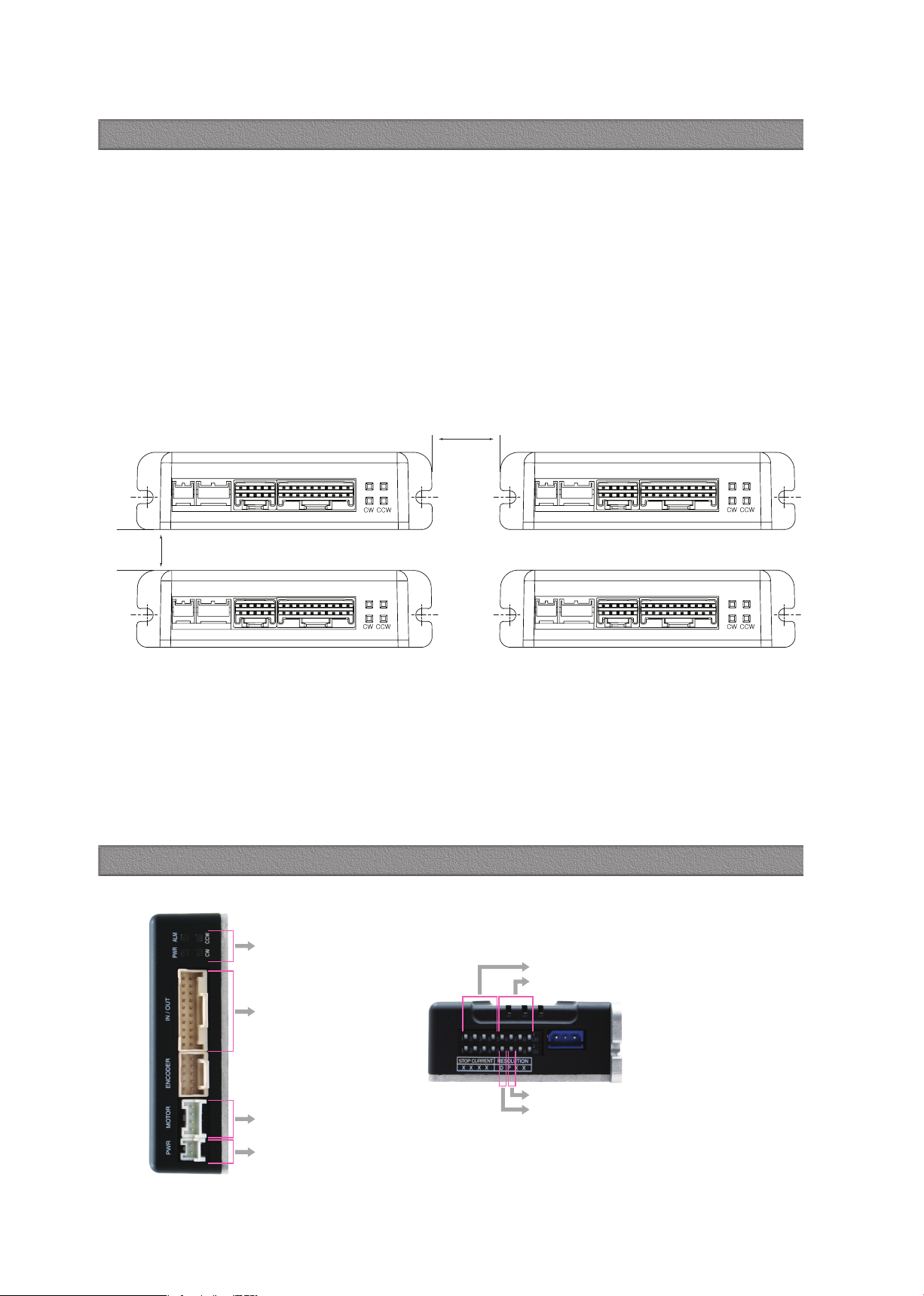
11. Notes on Installation
1) Ezi-STEP MINI is designed for indoor use only.
2) The ambient temperature of the room should be 0℃~50℃.
3) If the temperature of the product case is higher than 50℃, radiate heat of the outside to
cool down.
4) Do not install Ezi-STEP MINI under direct rays, near magnetic or radioactive objects.
5) If you set more than 2 drives, you must set over 20mm horizontally and over 50mm vertically
as shown below.
PWR MOTOR ENCODER IN/OUT PWR ALM PWR MOTOR ENCODER IN/OUT PWR ALM
PWR MOTOR ENCODER IN/OUT PWR ALM PWR MOTOR ENCODER IN/OUT PWR ALM
Drive status LED
Input/Output signal
connection(CN1)
Motor connection(CN3)
Power connection(CN4)
Stop current setting switch(SW1.1~1.4)
Resolution setting switch(SW1.5~1.8)
Pulse input setting switch(SW2.6)
Rotation direction setting switch(SW2.5)
12. Settings and Operation
More 20mm
More 50mm

www.fastech-motions.com - 12
Switch Position
STOP Current (%)
Switch Position
STOP Current (%)
4 3 2 1 4 3 2 1
ON ON ON ON 10 OFF ON ON ON 90
ON ON ON OFF 20 OFF ON ON OFF 100
ON ON OFF ON 30 OFF ON OFF ON 10
ON ON OFF OFF 40 OFF ON OFF OFF 10
ON OFF ON ON 50
*1
OFF OFF ON ON 10
ON OFF ON OFF 60 OFF OFF ON OFF 10
ON OFF OFF ON 70 OFF OFF OFF ON 10
ON OFF OFF OFF 80 OFF OFF OFF OFF 10
12.2 Stop Current Setting Switch(SW1.1~1.4)
Stop Current means the motor current value automatically set in 0.1 sec after motor stops. This is to prevent
the overheat of a motor when the motor is under long time idling. The unit of the selection value is a percentage.
*1 : Default : 50%
12.1 Drive Status LED
Indication Color Function ON/OFF Condition
PWR Green Power Input Indication Lights when power is ON Flashes when motor is
Free status
ALM Red Alarm Indication
Flash when protection function is activated
(Identifiable which protection mode is activated
by counting the flash times)
CW Yellow Motor Rotation Direction Lights when motor rotate CW direction
CCW Orange Motor Rotation Direction Lights when motor rotate CCW direction
◆ Protection functions and LED flash times
Times Protection Conditions
1Over Current Error The current through power devices in drive exceeds the
limit value
*1
2Over Speed Error Motor speed exceeded 3,000 [rpm]
3
Step Out
Error Abnormally motor do not followed pulsed input
5Over Temperature Error Internal temperature of a motor drive exceeded 85℃
6Over Regenerative
Voltage Error Back EMF more than 50V
7Motor Connect Error Power is ON without connection of motor cable to drive
9Motor Voltage Error Motor voltage is below 20V
11 System Error Error occurs in drive system
12 ROM Error Error occurs in Parameter storage Device(ROM)
*1 : Limit value depends on motor model
Alarm LED flash
(Ex, Step Out Error)
2.0s0.5s
12.3 Resolution Setting Switch(SW1.5~1.8)
*1 : Default: 10,000
The Number of pulse per revolution.
Switch Position Pulse/
Revolution
Switch Position Pulse/
Revolution
8 7 6 5 8 7 6 5
ON ON ON ON 500 OFF ON ON ON 6,400
ON ON ON OFF 1,000 OFF ON ON OFF 8,000
ON ON OFF ON 1,600 OFF ON OFF ON 10,000
*1
ON ON OFF OFF 2,000 OFF ON OFF OFF 20,000
ON OFF ON ON 3,200 OFF OFF ON ON 25,000
ON OFF ON OFF 3,600 OFF OFF ON OFF 36,000
ON OFF OFF ON 4,000 OFF OFF OFF ON 40,000
ON OFF OFF OFF 5,000 OFF OFF OFF OFF 50,000

www.fastech-motions.com - 13
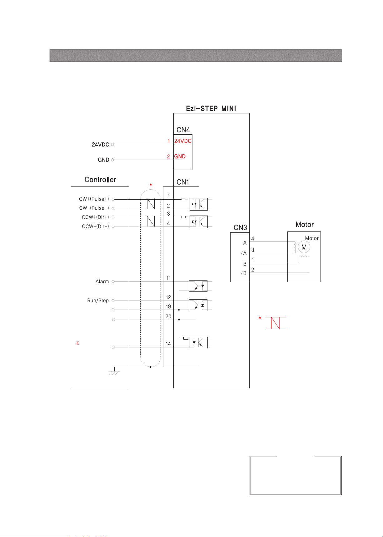
12.7 Motor Connector(CN3)
NO. Function I/O
1B Phase Output
2/B Phase Output
3/A Phase Output
4A Phase Output
12.8 Power Connector(CN4)
NO. Function I/O
124VDC Input
2GND Input
12.6 Signal Connector(CN1)
NO. Function I/O
1CW+(Pulse+) Input
2CW-(Pulse-) Input
3CCW+(Dir+) Input
4CCW-(Dir-) Input
11 Alarm Output
12 Run/Stop Output
14 Alarm Reset Input
19 EXT_GND Input
20 EXT_24VDC Input
Direction setting
switch: ON
Direction setting
switch: OFF
19
1
20
2
1 2 3 4
1 2
12.5 Pulse Input Setting Switch(SW2.6)
12.4 Rotational Direction Setting Switch(SW2.5)
Indication Switch Name Functions
PPulse input mode
Select Switch
Selectable 1-Pulse input mode or 2-Pulse input mode as Pulse input signal.
ON: 1-Pulse mode OFF: 2-Pulse mode ※ Default: 2-Pulse mode
Indication Switch Name Functions
DRotational Direction
Select Switch
Based on CW(+Dir signal) input to driver.
ON: CCW(-Direction) OFF: CW(+Direction) ※ Default: CW mode
CW(Pulse) Pin
CCW(Dir) Pin
Rotational Direction CW CWCCW CCW
2-Pulse Mode 1-Pulse Mode

www.fastech-motions.com - 14
13.1 Options
① Signal Cable
Available to connect between Input/Output Control System
and Ezi-STEP MINI.
Item Length [m] Remark
CSVI-S-□ □ □F
CSVI-S-□ □ □M
□ □ □
□ □ □
Normal Cable
Robot Cable
□ is for Cable Length. The unit is 1m and Max. 20m length.
② Motor Extension Cable
Available to extended connection between motor and
Ezi-STEP MINI.
Item Length [m] Remark
CMNB-M-□ □ □F
CMNB-M-□ □ □M
□ □ □
□ □ □
Normal Cable
Robot Cable
□ is for Cable Length. The unit is 1m and Max. 20m length.
③ Power Cable
Available to connect between Power and Ezi-STEP MINI.
Item Length [m] Remark
CMNB-P-□ □ □F
CMNB-P-□ □ □M
□ □ □
□ □ □
Normal Cable
Robot Cable
□ is for Cable Length. The unit is 1m and Max. 2m length.
Type Signal Cable Motor Cable Power Cable
Length supplied -30cm -
Max. Length 20m 20m 2m
①
②
③
13. System Configuration

www.fastech-motions.com - 15
Purpose Item Part Number Manufacturer
Power
(CN4)
Housing
Terminal
PAP-02V-S
SPHD-001T-P0.5 JST
Motor
Drive Side
(CN3)
Housing
Terminal
PAP-04V-S
SPHD-001T-P0.5 JST
Motor Side Housing
Terminal
5557-04R
5556T MOLEX
Signal
(CN1)
Housing
Terminal
501646-2000
501648-1000(AWG 26~28) MOLEX
13.2 Connector Specifications
Connector specifications for cabling to drive.
※ Above connector is the most suitable product for the drive applied. Another equivalent connector can be used.
www.fastech-motions.com - 16
Please refer to the Appendix when
connects motor extension cable.
Careful connection will be required to
protect the drive from any damages.
CAUTION
※ Alarm Reset signal line is also used for Motor Free signal.
(For details, please refer to Control Signal Input/Output Description)
※ When connects I/O cable between controller and drive, please turn off the power
of both controller and drive, in order to protect the drive from any damage.
Shielded
Twisted Pair
Cable
14. External Wiring Diagram

www.fastech-motions.com - 17
◆ CW, CCW Input
This signal can be used to receive a positioning pulse
command from a user host motion controller. The user can
select 1-pulse input mode or 2-pulse input mode. The input
schematic of CW, CCW is designed for 5V TTL level. When
using 5V level as an input signal, the resistor Rx is not used
and connect to the driver directly. When the level of input
signal is more than 5V, Rx resistor is required. If the resistor
is absent, the drive will be damaged. If the input signal level
is 12V, Rx value is 680ohm and 24V, Rx value is 1.8Kohm.
◆ Motor Free Input
This input can be used only to adjust the position by manually
moving the motor shaft from the load-side. By setting the
signal [ON], the drive cuts off the power supply to the motor.
Then, one can manually adjust output position. When setting
the signal back to [OFF], the drive resumes the power supply
to the motor and recovers the holding torque. When driving a
motor, one needs to set the signal [OFF]. In normal operations
set the signal [OFF] or disconnect a wire to the signal.
◆ Alarm Reset Input
When a protection mode has been activated, a signal to this
Alarm Reset input cancels the Alarm output. By setting the
alarm reset input signal [ON], cancel Alarm output. Before
cancel the Alarm output, have to remove the source of alarm.
[Caution] If Alarm Reset input signal still remains [ON], motor will be
Free state. Keep in mind to change [ON]→[OFF] state.
1
Input Signal
Input signals of the drive are all photocoupler protected.
The signal shows the status of internal photocouplers
[ON: conduction], [OFF: Non-conduction], not displaying
the voltage levels of the signal.
◆ Alarm Output
The Alarm output indicates [OFF] when the drive is in a
normal operation. If a protection mode has been activated, it
goes [ON]. A host controller meeds to detect this signal and
stop sending a motor driving command.
When the drive detects an abnormal operation such as
overload of overcurrent of a motor, it sets the Alarm output to
[ON], flash the Alarm LED, disconnects the power to a motor
and stops the motor, simultaneously.
2
Output Signal
As the output signal from the drive, there are the
photocoupler outputs (Alarm, Run/Stop). The signal status
operate as [ON : conduction], [OFF : Non-conduction] of
photocoupler not as the voltage level of signal.
◆ Run/Stop Output
Run/Stop Output state is [ON] when motor positioning is
completed. It operates reversely compare to Normal mode,
when you set inverse mode.
Pin No. Function
1 CW+
2 CW-
3 CCW+
4 CCW-
Pin No. Function
14 Alarm Reset/
Motor Free
20 EXT_24VDC
Pin No. Function
11 Alarm
12 Run/Stop
19 EXT_GND
Alarm Reset signal line is also used for Motor Free signal.
15. Control Signal Input/Output Description
www.fastech-motions.com - 18
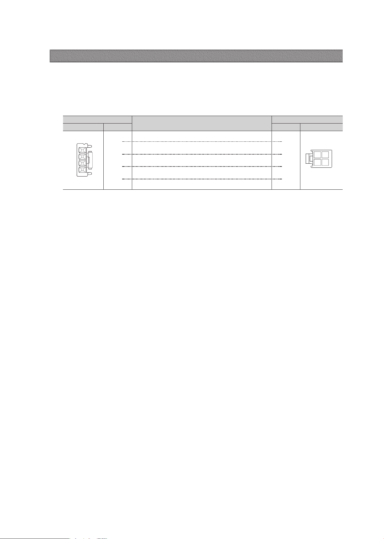
Connector of Drive wiring Connector of Motor
Pin layout Pin number Pin number Pin layout
1
2
3
4
1
3
4
2
3 1
4 2
1
2
3
4
Appendix
■ Extension Cable for Motor
For cable extension between Motor and Drive.
WIRING DIAGRAM

www.fastech-motions.com - 19
MEMO

'"45&$)$P
-UE
3NEPOH#VDIF
PO5F DIOP1BSL
1Z
FPOHDIFPOSP#VDIFPOTJ(ZFPOHHJEP
3FQVCMJDPG,
PSFB1PTUBM$PEF
5&-
'"9
&NBJMTBMFT!G
BTUFDINPUJPOTDPN
)PNFQBHFXXXGBTUFDINPUJPOTDPN
ś൞ഔ
լ׆ܑవඌవߦ
వഓڋ൞ܛ
5&-'" 9
&NBJMUFBN@TBMFT!GBTUFDINPUJPOTDPN
)PNFQBHFXXXGBTUFDINPUJPOTDPN
www.fastech-motions.com
· It is prohibited to unauthorized or reproduced in whole or in part described in the
User’s Guide
· If you need a user manual to the loss or damage, etc., please contact us or your
nearest distributor.
·
User manual are subject to change without notice to improve the product or
quantitative changes in specifications and user’s manual.
·
Ezi-STEP is registered trademark of FASTECH Co., Ltd in the national registration
ⓒ Copyright 2007 FASTECH Co., Ltd. May 28, 2021 Rev.2
Table of contents
Other Fastech Industrial Equipment manuals


Popular Industrial Equipment manuals by other brands


Duro Dyne
Duro Dyne GBAC ROTO BONDER owner's manual

OPTIMUM Maschinen
OPTIMUM Maschinen K11-160 operating manual

ABB
ABB XAC20409 Operation manual

Excelitas Technologies
Excelitas Technologies OmniCure S1500 PRO user guide

BIRD
BIRD Termaline 8890 Series Instruction book

SeaSoft
SeaSoft MobilSwitch-Micro-C manual