AND AD-3255 User manual

Ultrasonic Thickness Gage
1WMPD4003292A

Note
No part of this publication may be reproduced, transmitted,
transcribed, or translated into any language in any form by any
means without the written permission of A&D Company, Limited.
The contents of this manual and the specifications of the
instrument covered by this manual are subject to change for
improvement without any notice and obligation on the part of the
manufacturer.
2017 All rights reserved.
ULTRAGEL II , HIGH Z and SONO are registered trademarks
of the Magnaflux company.

-1 -
Contents
1. Safety Information ....................................................................2
1-1-1. Meaning of Alert Indications ................................................2
1-1-2. Cautions Concerning Safety Indications..............................2
1-1-3. Cautions Concerning Performance .....................................3
2. Introduction ..............................................................................4
2-1. Features .................................................................................4
3. Overview "
Unpacking, Names, Operation & Response
".........................6
3-1. Unpacking ..............................................................................6
3-2. Names....................................................................................7
3-3. Operation and Response........................................................8
4. Measurements........................................................................ 11
4-1. Preparation........................................................................... 11
4-2. Basic Measurement..............................................................12
4-2-1. Primary Operation.............................................................12
4-2-2. Probe -Zero Function ......................................................14
4-2-3. Switching the Display Resolution ......................................15
4-2-4. Switching Measurement Modes ........................................15
4-3. Sound Velocity Calibration....................................................16
4-3-1. Use of Sound Velocity Calibration .....................................16
4-3-2. Calibration of Known Sound Velocities..............................17
4-3-3. Calibration of Unknown Sound Velocities..........................17
4-3-4. Two point calibration for Sound Velocities .........................18
4-3-5. Initialization of Sound Velocities ........................................19
4-3-6. Pre-installed Sound Velocities..........................................20
5. Information and Cautions .......................................................21
5-1. Battery..................................................................................21
5-2. Transducer ...........................................................................21
5-3. Measurement of the Tube & Pipe .........................................24
5-4. Couplant...............................................................................26
5-5. Measurement Principle.........................................................27
5-6. Reference Data of Sound Velocities .....................................28
6. Specifications .........................................................................29

-2 -
1.
Safety Information
This section describes information to use the AD-3255 safely and
to prevent injury.
1-1-1.
Meaning of Alert Indications
All safety messages are identified by the following of ANSI Z535.4.
Each alert indication has the following meaning.
Warning Definitions
Warning
A potentially hazardous situation which, if not avoided,
could result in death or serious injury.
Caution
A potentially hazardous situation which, if not avoided,
may result in minor or moderate injury or damage to the
instrument.
This is a hazard alert mark.
Operation is prohibited.
Others
Caution
An important description for proper use of the instrument.
Note
The information that helps users operate the instrument.
1-1-2.
Cautions Concerning Safety Indications
Caution
Repair Only authorized individuals may open the case and repair the
AD-3255. Loss of data or malfunctions may result from
opening the case. Contact your local dealer or our service
department to resolve the issue.
Failure Should the AD-3255 experience a malfunction, stop usage
immediately, post a notice indicating "
Out of Order
" on the
AD-3255 and move it to place where it will not be used by
mistake. Continued usage of it in this state is very dangerous.
Contact your local dealer for repair.

-3 -
1-1-3.
Cautions Concerning Performance
Gently use the AD-3255 because of the precision instrument.
Strong impacts could result in a malfunction.
Use the accessory carrying case for transport.
The main unit and transducer are calibrated as pair in the factory.
Failure to use an authorized transducer may result in incorrect
thickness measurements. Always keep the main unit and transducer
as pair when asking for a repair.
The AD-3255 is not waterproof. Avoid water, moisture, oil and dust.
Avoid an extreme temperature change or impact. Do not immerse
the transducer in water or oil.
Avoid contaminating the transducer connector with water, oil and dust.
Use the accessory strap as needed.
Example: Tie the strap to the main unit to avoid losing the test piece.
Tie the strap to the main unit to prevent the set from
being stored in a piecemeal fashion.
Do not pull excessively on or sharply bend the transducer cable.
Clean the main unit using a lint free cloth that moistened with water
and neutral detergent. Clean the connectors and electrical
terminals using a dry lint free cloth.
Operating temperature range : 0 [°C] to 50 [°C]
Remove the batteries from the main unit when the AD-3255 is not
used for a long time.

-4 -
2.
Introduction
Congratulations on purchasing an ultrasonic thickness gage
AD-3255 of . We recommend that you read
through this manual carefully before using the AD-3255 for the first
time. Keep the manual nearby for reference.
2-1.
Features
The AD-3255 can measure the thickness of various materials using
a principle similar to sonar, displays the thickness value in 0.1 [mm]
or 0.01 [mm]units, and is equipped with a multimode feature.
The multimode feature
Pulse - Echo Mode
Use this mode for basic measurements or detection of flaws,
cracks and pits.
Echo - Echo Mode
When measuring the thickness, use this mode to eliminate
errors concerned with measuring coating and paint thickness.
Use the optional transducer, AD-3255-04.
The sampling mode
Single Point Mode
This mode can measure single point thickness where the
transducer is placed.
Sampling rate : 7[times/ second]
Scan Mode
This mode can display a minimum value from thickness in
areas where the transducer has been moved.
Sampling rate : 16 [times/ second]

-5 -
Probe-Zero Function
The AD-3255 is equipped with a probe-zero function to calibrate
the zero point of the transducer in the pulse -echo mode.
The sound velocity can be calibrated with a single point calibration,
two point calibration or numerical input.
The coupling state symbol indicates the state of the transducer
contacting the material surface.
The AD-3255 can store user settings and calibration data.
The battery indicator indicates the battery power.
The AD-3255 is equipped with an automatic power-off function:
When no operation is performed for approximately 5 minutes, the
display blinks for 20 seconds and then the power is turned off.
The AD-3255 can measure the thickness of other metal, plastic,
ceramics, composite materials, epoxy resin, glass and a variety of
other materials.
The range of sound velocity: 1000 to 9999 [m/s],
The range of thickness: 0.8 to 200 [mm],
Using the accessory transducer.

-6 -
3.
Overview "
Unpacking, Names, Operation & Response
"
3-1.
Unpacking
Upon receiving the product, inspect the main unit and accessories
contained in the package. Should anything be missing or damaged,
contact and consult your local dealer.
Use the carrying case for transport.
Packing list is as follows:
Main unit .......................................................................................................................... 1
Test piece "
is equivalent to the thickness of
4.00
mm
" AD-3255-01
.... 1
Transducer for the pulse -echo mode AD-3255-02 .... 1
Carrying case ............................................................................................................... 1
Empty bottle for the couplant .............................................................................. 1
Strap ................................................................................................................................... 1
Instruction manual "
This manual
" ........................................................................ 1
Main unit Test piece Bottle
Strap
Transducer for the
pulse -echo mode Carrying case This manual

-7 -
3-2.
Names
Coupling state
Battery indicator
Measurement mode
Units
Transducer connector "Transmitter"
Transducer connector "Receiver"
Battery cover
which covers the battery
box in which two
alkaline batteries, "LR6,
AA" can be installed.
Strap holes
Switches :
When pressed,
the buzzer sounds.
Display :
Thickness data and
settings are displayed.
References
Transducer for
the pulse - echo mode
Plugs

-8 -
3-3.
Operation and Response
Switches
Turns the AD-3255 on/off.
Turns the backlight on/off.
Changes the display resolution to 0.1 [mm]or 0.01 [mm].
Press the switch while pressing and holding the
switch after turning off the main unit.
Enters the sound velocity settings from the measurement.
Returns the measurement from the sound velocity
settings.
Starts the probe -zero function from the measurement.
Specifies a connected transducer in the probe -zero
function.
Increases the parameter in the setting mode.
Selects a measurement mode in the measurement.
Single point mode....................... Indication
Measures the thickness in the space where the
transducer is placed on the material surface.
Sampling rate : 7[times/sec.]
Scan mode............................................ Indication
Displays a minimum thickness from the measured data
in the area where the transducer has been moved.
Sampling rate : 16 [times/sec.]
Decreases the parameter in the setting mode.
Selects the measurement mode.
Pulse - echo mode....................... Hide +, Indication
This mode is for major measurements and can be used
to detect a flaw or pit.
Echo - echo mode....................... Show +, Indication
This mode can be measure the thickness that is
eliminated errors concerned with measuring coating
and paint thickness.
-9 -
Cautions
Use the optional AD-3255-04 transducer if a thickness is
measured using the echo -echo mode.
The backlight consumes the battery power.
The AD-3255 can not perform in other modes while the current
mode is active or busy. For example :
During sound velocity calibrations, the probe-zero function can
not be performed.
During thickness measurements, numerical input is unavailable.
While setting information is displayed, switches cannot be
operated.
Coupling Indication
The AD-3255 can indicate the coupling state between the
transducer and material surface. The symbol indicates stable
and measurable contact. The blinking symbol indicates
unstable and weak contact. When the measurement is complete,
the buzzer sounds.
Units
The units of thickness [mm]or sound velocity [m/s]are displayed.
The unit [in]is not displayed.
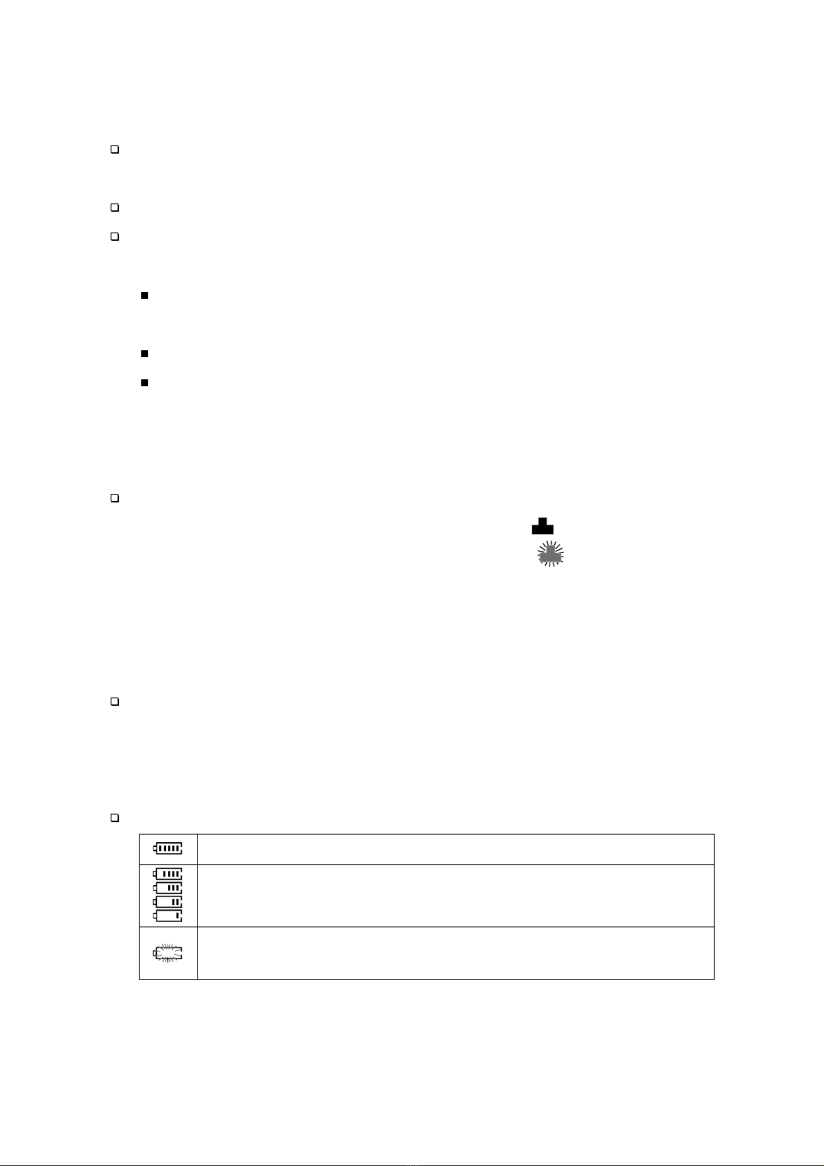
Battery Indicator
The blocks indicate the state of to the battery.
Adequate battery power.
Blocks indicate changes in battery power levels.
The battery power has been consumed.
Replace with two new alkaline batteries, "LR6, AA".
-10 -
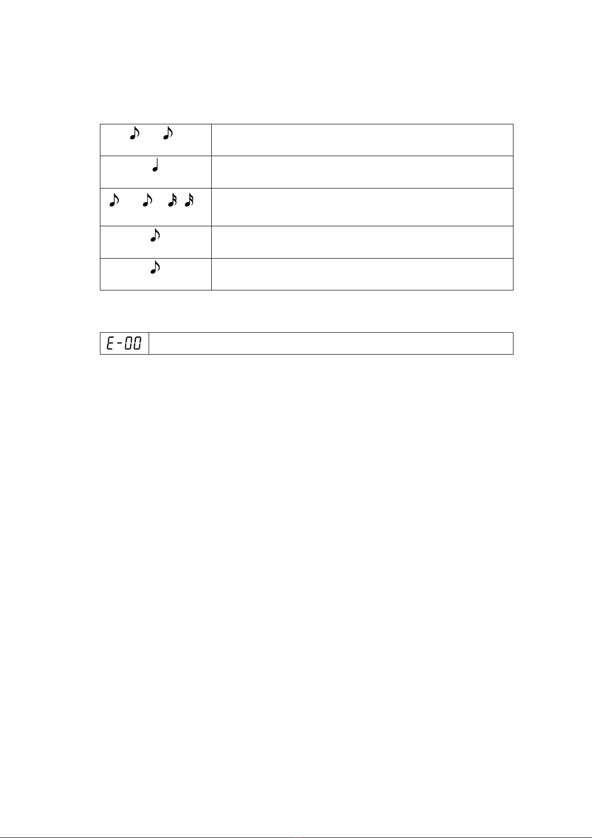
Buzzer
Different buzzer sound types indicate the following:
___ _
pitt pitt Turning on the AD-3255.
pii Turning off the AD-3255.
___ __ _ _
pitt pitt pitt pitt
Initializing sound velocity or when changing
display resolution.
pitt Switch response
pitt Measuring thickness.
Error Code
Battery power has been consumed.
Contact your local dealer for any error other than error code
displayed above.

-11 -
4.
Measurements
4-1.
Preparation
Step 1.
Install
"or Replace"
Batteries.
Open the battery cover.
Install two new alkaline batteries
matching polarities "+and -" with
those of the electrical terminals.
Close the battery cover.
Step 2.
Connect Plugs of the Transducer.
Connect the plugs of the transducer to the
connectors on the main unit.
The connector can connect either the
transmitter plug or receiver plug.
Clean the plug if couplant is present.
Step 3.
Prepare the Couplant.
Prepare the couplant using the bottle.
Step 4.
Prepare the Test Piece.
Prepare the accessory test piece with
an equivalent thickness of 4.00 mm.
Put the couplant on the surface of the
test piece.
Step 5.
Prepare a Material Sample Piece.
Prepare a sample piece to measure the thickness.
Apply couplant to the surface of the material.
Plug
Connecto
r
LR6 or AA
batteries
Battery cove
r
Battery box
Bottle
Couplant
Test piece
Couplant

-12 -
4-2.
Basic Measurement
4-2-1.
Primary Operation
Step 1.
Turn on the Main Unit.
Press the switch to turn on the main unit.
The buzzer sounds "pitt pitt".
The of the pulse -echo mode is displayed.
The of "the initial" sound velocity is displayed.
Step 2.
Confirm the Sound Velocity
"if necessary".
Press the switch twice.
Confirm the of the sound velocity for
the test piece. Select it using the switch
from pre-installed values "or using the
switch and switch", if necessary.
Press the switch to store it.
Step 3.
Specify the Transducer
"if necessary"
.
Press the switch to display the current
transducer. Specify the using the
switch and switch.
Step 4.
Calibrate the Zero Point.
Contact the transducer to the surface of
the test piece coated with couplant.
The calibration is finished when the
indicator is displayed, 4.00 [mm] is
measured and the buzzer sounds "pitt".
Test piece
Couplan
t
Resul
t
o
r
Twice
Select

-13 -
Step 5.
Measure the Material.
Contact the transducer to the surface of
the material. The indicator is
displayed and the thickness is
measured.
Step 6.
Turn off the Main Unit.
Press the switch to turn off the main
unit. The buzzer sounds "pii".
Thickness
Material
Transduce
r
Version
Turn off

-14 -
4-2-2.
Probe - Zero Function
Use this function to calibrate the zero point concerning the pulse -
echo mode. Don't use this function for the echo -echo mode.
Step 1.
Confirm the Sound Velocity
"if necessary".
Press the switch twice in the
measurement mode.
Confirm the of the sound
velocity for the test piece. Select it using
the switch from pre-installed
values "or using the switch and
switch", if necessary.
Press the switch to store it.
Step 2.
Specify the Transducer.
Press the switch to display the current transducer.
Specify the using the switch and switch.
AD-3255-02 Accessory
AD-3255-03 Option
AD-3255-04 Option
Not used
Step 3.
Calibrate the Zero Point.
Contact the transducer to the surface of the
test piece coated with couplant.
The calibration is finished when the indicator
is displayed, 4.00 [mm]is measured and
the buzzer sounds "pitt".
Twice
Selec
t
o
r
Test piece
Couplan
t
o
r
Transduce
r

-15 -
4-2-3.
Switching the Display Resolution
Press the switch to turn on the main unit while
pressing and holding the switch after turning
off the main unit. The display resolution is switched
to 0.1 [mm]or 0.01 [mm].
4-2-4.
Switching Measurement Modes
The following modes in the measurement can be selected.
Single Point Mode
The are displayed when the switch is
pressed in the measurement mode. This mode can measure
single point thickness where the transducer is placed.
Sampling rate : 7[times/sec.]
Scan Mode
The are displayed when the switch is pressed
in the measurement mode. This mode can display a minimum
value from the thickness in the area where the transducer has
been moved. Sampling rate : 16 [times/sec.]
In this mode, any brief interruptions "example: a week contact,
no couplant area, etc." less than 2 seconds in the signal will be
ignored.
When the "blinking symbol " is displayed, and the contact of
the transducer is lost for 2 seconds or more, the AD-3255 will
display the smallest measurement data.
The measurement value blinks 5 times when a minimum value
is displayed.
The AD-3255 doesn't store the scan mode settings. The single
point mode will run when restarting the AD-3255.
Turning off
Example:
The display resolution has been exchanged from 0.01 [
mm
] to 0.1 [
mm
].

-16 -
4-3.
Sound Velocity Calibration
Cautions
Confirm the [m/s]to the sound velocity when calibrating
the sound velocity using the accessory test piece. The settings are
not needed if the sound velocity has not changed.
Sample piece whose coating or paint has removed is required for
both the single point and the two point calibrations. If the sample
piece's coating or paint is not removed, a correct thickness value
can not be displayed.
In order to keep the accuracy of the measurement, use sample
pieces of known thickness.
4-3-1.
Use of Sound Velocity Calibration
"The single point calibration" is the simplest and is commonly
used as the calibration procedure that can optimize the linearity in
a wide range.
The method to input the sound velocity using numerical switches.
Refer to "
4-3-2
.
Calibration of Known Sound Velocities
".
The method to calculate the sound velocity based on known
thickness of sample piece.
Refer to "
4-3-3
.
Calibration of Unknown Sound Velocities
".
"The two point calibration" allows for greater accuracy over a small
range by calculating the probe-zero function and sound velocity
calibration.
Refer to "
4-3-4.
Two point calibration for Sound Velocities
".
The method to restore to the sound velocity of the test piece.
Refer to "
4-3-5
.
Initialization of Sound Velocities
".
The method select a sound velocity from pre-installed values.
Refer to "
4-3-6
.
Pre-installed Sound Velocities
".

-17 -
4-3-2.
Calibration of Known Sound Velocities
Step 1.
Numerical Input of the Sound Velocity.
Press the switch twice in the measurement mode.
Display the sound velocity using the
switch from pre-installed value
"or using the switch and switch".
Press the switch to store.
Refer to "
5-6
.Reference Data of Sound
Velocities" concerning principal sound velocities.
4-3-3.
Calibration of Unknown Sound Velocities
Prepare a sample piece that the thickness is known.
Step
1
.
Perform the Probe-Zero Function.
Perform the "
4-2-2
. Probe - Zero Function".
Step
2
.
Measure the Thickness of Sample Piece.
Apply couplant to the surface of the sample
piece. Press the transducer against it. The
thickness value is displayed.
Remove the transducer from the surface
after the measurement.
Step
3
.
Input the Thickness Value.
Press the switch. The mm blinks.
Input the thickness value using the
switch and switch.
Press the switch to store.
The sound velocity is calculated.
Press the switch to return to
the measurement.
Twice
Selec
t
o
r
o
r
Thickness Inpu
t
Calculated velocity
Thickness
Measure it and remove the transduce
r
Sample piece
Cou
p
lant

-18 -
Measure it and remove the
t
ransduce
r
Sample piece
Measured value
Couplant
4-3-4.
Two point calibration for Sound Velocities
Prepare a sample piece "or two pieces" whose thickness are
known.
Step
1
.
Perform the Probe-Zero Function.
Perform the "
4-2-2
. Probe - Zero Function".
Step 2.
Measure the Thickness of the First Point.
Apply couplant to the first point of the
sample piece. Press the transducer
against it. The thickness value of the
first point is displayed.
Remove the transducer from the
surface after the measurement.
Step 3.
Input the Value of the First Point.
Press the switch. The mm blinks.
Input the value of the first point using
the switch and switch.
Press the switch to display
of next step.
Step 4.
Measure the Thickness of the Second Point.
Apply couplant to the second point of
the sample piece. Press the transducer
against it. The thickness value of the
second point is displayed.
Remove the transducer from the
surface after the measurement.
o
r
Corrected value
Proceed next step
Measure it and remove the
t
ransduce
r
Measured value
Table of contents
Other AND Measuring Instrument manuals


