2mm and 3mm
alan key
screwdriver
philips head
(cross head)
x29
M3 x 16mm
long screw
x4
M5 x 8mm
counter
sunk screw
x2
6mm
washer
x2
6mm
penny
washer
ANDERSEN A2
x2
M5 x 12mm
long screw
OPERATION LED STATUS
System powering up. Red, Amber, Green
LED flash together twice a second
Standby State (solid green)
Vehicle connected state (solid green & solid
amber)
Vehicle charging state (solid amber)
Charge point locked or awaiting scheduled
charge (solid green & solid red)
ERROR & UPDATE LED STATUS
Disconnected from network/cloud (green
LED flash every 5 seconds)
RCM or charge error (blip red every sec-
ond)
Firmware upgrade (sequence of green,
amber, red for duration of upgrade)
SETUP LED STATUS
Wifi Setup (Amber LED flash once per second)
Reset warning. Red, Amber, Green LED flash
4 times per second.
SETUP MULTI FUNCTION OPERATION
Reset RCM (Two button presses)
Enter Network setup mode (Three button
presses)
Exit Network setup mode
(One button press)
Enter unit reset mode (Five button presses)
+ Exit Timeout 30 secs
x2
x3
x1
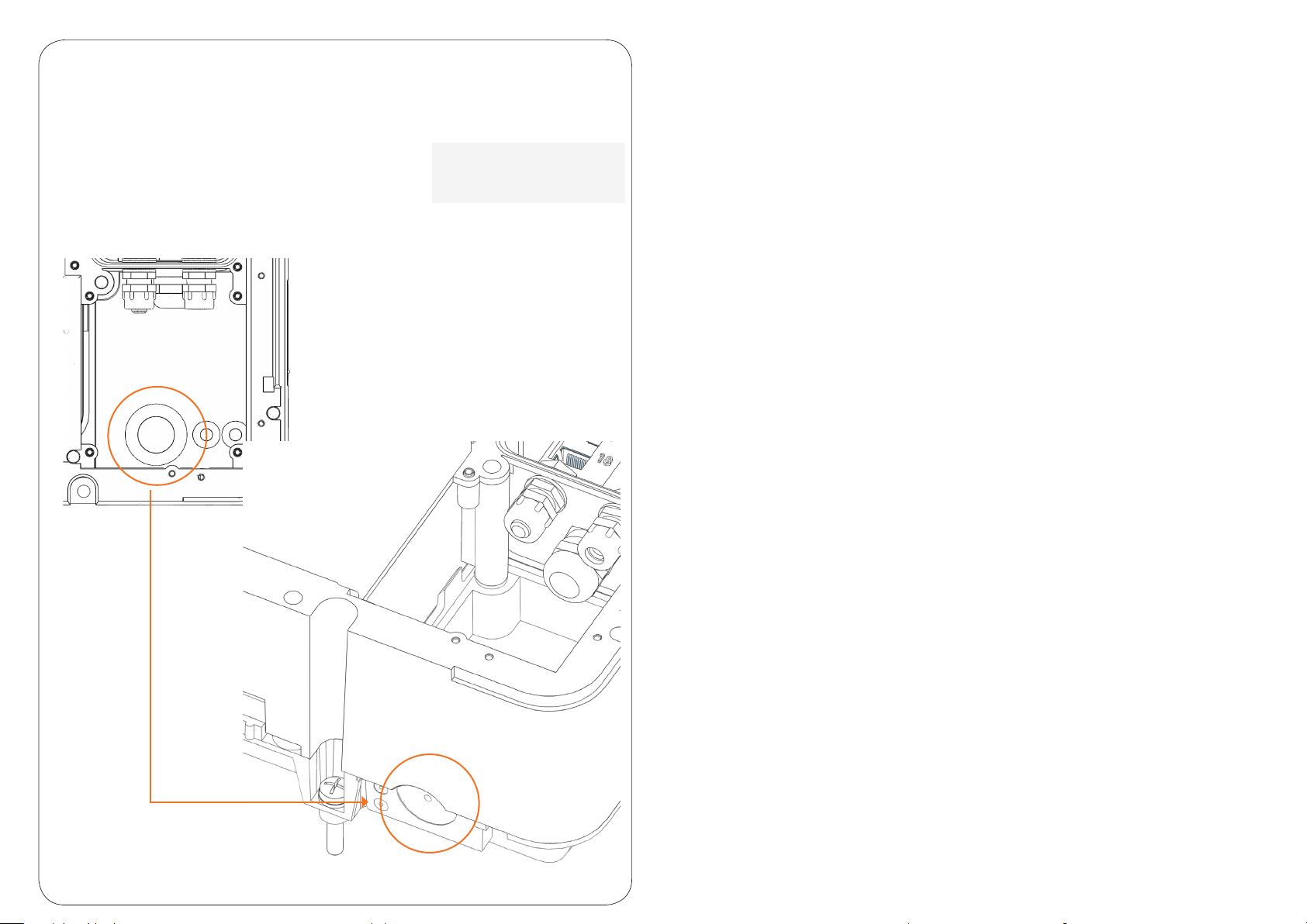
Multi function
button located
at the bottom
left inside the
cable slot
x5