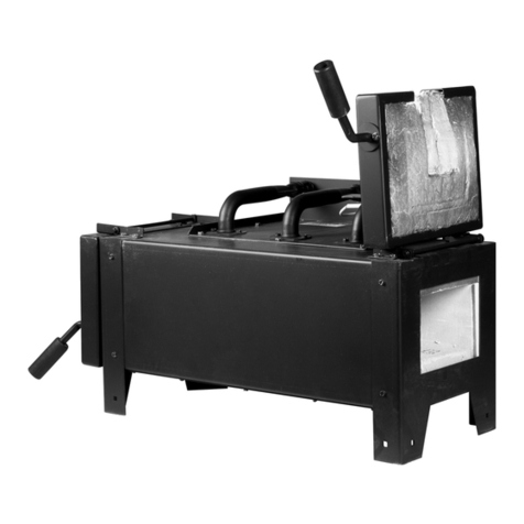
Anderson FFAH21 User manual

Anderson Thermal Solutions (Suzhou) Co., LTD
FFAH21 Burner Operation Manual
No:
ATS–Operation Manual–FFAH21
Subject::
FFAH21 Burner Operation Manual
Version :
V1.0
Author :
Wilson Sun
Review :
David

Anderson Thermal Solutions – FFAH21 Burner Operation Manual
Anderson Thermal Soluions(Suzhou)Co., Ltd
Content
1. Disclaimer Notice............................................................................................................................ 1
2. Liability and Warranty..................................................................................................................... 1
3. Safety instructions .......................................................................................................................... 1
4. Description...................................................................................................................................... 2
5. Spare parts...................................................................................................................................... 7
6. Appendix ......................................................................................................................................... 7

Anderson Thermal Solutions – FFAH21 Burner Operation Manual
Anderson Thermal Soluions(Suzhou)Co., Ltd
1
This manual has been written for those who are already familiar with all aspects of nozzle mix burner
and its add-on components. Main contents of the manual including safety rules, burner installation,
commissioning, operation parameters, maintenance and troubleshooting, spare parts, etc.
1. Disclaimer Notice
Anderson Thermal Solutions (Suzhou) Co., Ltd. reserves the right to change the construction and/or
configuation of our product at any time without informing customers.
If the product or its individual modules are used for purposes other than the designated purpose,
their effectiveness and suitability must be confirmed.
Anderson warrants that the product itself will not infringe any patents. Every effort has been made
to make this manual as accurate and complete as possible. If you find errors or omissions, please
contact us so we can correct them.
2. Liability and Warranty
Due to negligence, breach of warranty or other reasons, Anderson's liability for its products is limited
to the provision of such replacement parts and will not be liable for any other injury, loss or expense,
whether direct or indirect, including but not limited to loss of or damage to the use of materials that
sell, install, use, fail to use or repair or replace Anderson related products.
The warranty is void if: any operation explicitly prohibited in this manual, any adjustment or assembly
process not recommended or authorized.
3. Safety instructions
Only those who were trained and qualified person can follow the manual to operate or adjust the
combustion system. The fire was prohibited within a radius of 5 meters of the combustion system.
Flame, non–covered light sources or heat sources shall not be brought to the combustion area unless
it is related to the process. Welding in combustion control area shall be approved to ensure the safety
in the area and also preventive measures should be taken into consideration.
Before starting, the operator must confirm whether the burner and gas pipeline are in normal
working condition, and there is no flammable substance around the burner. The burner must be
operated with fuel and oxygen or air. The ignition and operation of the burner must be performed at
the specified position. The burner has been correctly and safely installed before ignition. The ignition
of the burner needs to be performed after the combustion chamber is purged. If it is ignited at a low
temperature, it needs to be replaced with 5 times the volume of the combustion chamber to avoid
explosion.
However, it is not necessary to purge when the temperature is higher than 750°C. Air pipe or gas pipe
connected with burner should be tight enough with no leakage, also the periodically check air or fuel
nozzles of the burners to prevent to be blocked by dust, slag or other materials.
Anderson Thermal Solutions – FFAH21 Burner Operation Manual
Anderson Thermal Soluions(Suzhou)Co., Ltd
2
ATTENTION:DANGER OF BEEN BURNT
When burner in operation, combustion is severe, so the burner must be fixed. Hoses or cables in area
of the combustion system must be suitable for high temperature, to prevent high temperature failure
or cause safety accidents. Burners should be periodically inspected and cleaned. Copper wire brush
may be used, if necessary, to clean burner head. The burner system should be checked twice a year
for safety operation.
4. Description
FlexFire® air series burner is a patented product of Anderson Thermal Solutions (Suzhou) Co., Ltd. It
is suitable for solid waste incineration, glass melting furnace. FFAH series burner with heated air
temperature up to 700°C and flame temperature is up to 2000°C. t is a high-performance burner with
independent intellectual property rights, utilizing most up-to-date technology for green fuel
combustion, and adjustable mechanism for flame length and energy release position.
The hydrogen/oxygen gases will be supplied through the center of the burner insert gun, with a
mechanical adjustment mechanism can adjust the position inside the burner. Hydrogen and oxygen
will be supplied with premixed with proper ratio, inject in to center of flame, extremely enhanced
the flame temperature, improve the fuel cracking, and thoroughly improve burner radiation heat
efficiency.
Figure 1: FlexFire®-Hot Air Hydrogen Oxygen Burner

Anderson Thermal Solutions – FFAH21 Burner Operation Manual
Anderson Thermal Soluions(Suzhou)Co., Ltd
3
Attention!
–When the internal cooling air supply stops for more than 20
minutes, remove the burner and seal the seal plate. Prevent
burner damage.
–External cooling air supply for a long time will cause damage to
the sealing plate.
–To adjust the firing gun, loosen the corresponding fixing bolt and
lock it again after the adjustment is completed
–Do not remove the metal gas hose or locking device when the
gas is not completely shut down
4.1 Burner data sheet
Model Power Input
(kW)
Gas Flow
(NM3/H)
O
2
Flow
(NM3/H)
H
2
Flow
(NM3/H)
Gas inlet Pressure
(KPa)
Heated air Flow
(NM3/H)
Heated air inlet
Pressure (KPa)
Min
Max
Max
Max
Min
Max
Min
Max
Min
Max
20G300 75-300 7.5 30 2.8
5.5
0.5 10 60 266 0.25 5.0
20G600 150-600 15 60 10.5
21
0.5 10 150 700 0.25 5.0
20G1200 300-1200 30 120 21
42
0.5 10 300 1600 0.25 5.0
Typical Dimension (Use 20G600 as reference, burner actual length and inlet position could be
adjusted according to actual application)
Model Gas inlet size Air inlet size
20G300
1.5”
2.5”
20G600
1.5”
3”
20G1200
2”
4”
Figure 2: Typical Dimension (Use 20G600 as reference)

Anderson Thermal Solutions – FFAH21 Burner Operation Manual
Anderson Thermal Soluions(Suzhou)Co., Ltd
4
4.2 Installation of the burner
Inspect burners and burner blocks for obvious damage. Inspect and clean the inside of the block holes
to prevent debris from obstructing gas and flames.
Fix the burner with four T-bolts corresponding to the four T-slots of the burner block with nuts on
the burner block, check whether the center of the burner is aligned with the center line of the block
hole, and at the same time, the block and the burner are horizontal due to the overall level. Tighten
all mounting bolts. Connect the burner combustion airline to the flanged hot air inlet. The weight of
the burner body must be borne by the burner support frame to avoid the burner bearing the force
of the pipeline.
Connect the gas line to the corresponding connection on the burner. If the burner uses fuel, you need
to connect the fuel and atomizing gas lines to the corresponding connections.
Use Stainless Steel tubing for hydrogen/oxygen fuel connection, use SS316 and above material for
compression fitting for quick connections, Swagelok connectors are recommended, to ensure the
tightness connection, and bubble test after connected.
Attention!
–Gas and cooling air must be equipped with check valves,
otherwise tempering may occur.
–Ensure that the furnace temperature is above the minimum
requirement for the ignition point of the fuel.
–The combustion air is hot air. Please pay attention to protect it
from burns during installation and operation.
–Must use qualified material for hydrogen/oxygen gas
connection
4.3 Burner start
Before starting, verify that all shut-off valves for fuel, atomized air and natural gas are closed. Open
the butterfly valve on the hot air downstream tube until the desired air flow is reached. The flow rate
can be obtained by providing the differential pressure display value and the orifice plate calculation
book on the metering device. When the burner uses fuel: Open the pressure gauge isolation valve on
the fuel and atomizing air lines. Turn on the atomizing air again. Adjust limiting orifice valve until the
desired flow rate (or pressure) is reached. Open the fuel shutoff valve in the fuel downstream pipe
and adjust the oil flow to the required amount. The burner uses natural gas: open the pressure gauge
isolation valve on the gas line. Open the manual stop valve on the gas pipeline and adjust the gas
volume. Make sure the burner is firing. Make adjustments based on your desired flame length. Fine-
tune the air-fuel (gas) ratio.
Repeat the above steps until all burners are ignited. When the heat up burner shuts down, the flame
shape can be adjusted by increasing all fuel flow to the operating level. For the oil nozzle, adjust the
atomizing air flow to help optimize flame. At this point, the hot air burner needs to be tuned several
times until the standard glass pull capacity is reached and the final adjustment is made.
The hydrogen/oxygen gas can only be supplied to burner when the supply system is stable and
reliable to run.

Anderson Thermal Solutions – FFAH21 Burner Operation Manual
Anderson Thermal Soluions(Suzhou)Co., Ltd
5
The minimum hydrogen/oxygen flow should be maintained, and it must be over 1/4 of the designed
hydrogen/oxygen in any circumstance.
If the production rate decreases, the inner tube may need to be repositioned to provide the proper
flame length. Move the natural gas inner nozzle forward to shorten the flame; move the natural gas
inner nozzle backward to extend the flame.
4.4 Burner shut down
To close the burner, first close the hydrogen/oxygen supply, then fuel (gas or oil), and then close the
atomizing air shutoff valve of the burner (gas is not applicable). Close the combustion air butterfly
valve to allow only a small amount of air to enter the burner for cooling. If the burner is switched off
for a long time, the gun body assembly must be pulled out. Close the burner block hole and do not
allow hot gas to escape through the burner block hole.
4.5 Flame length adjustment
FFAH21 burner is mainly composed of preheating combustion air duct and burner body. Hot
combustion air enters the burner through the combustion air inlet at a controlled pressure and flow.
The gas enters through the gas inlet at the specified flow rate and pressure, and immediately mixes
with the hot combustion air and ignites.
By moving the position of the gas burner (red arrow), you can change the air flow of the burner and
affect the flame. In most cases, this adjustment is not necessary because the initial position "0"
provides a good flame for the burner. If you need to increase the combustion air, you can reduce the
pressure drop of the combustion air through the burner by pulling the gas gun out of the scale, so
that the air flow can be increased under the existing air pressure. If you need to reduce the
combustion air, you can increase the pressure drop of the combustion air through the burner by
pushing the gas gun to a scale, so that the air flow can be reduced under the existing air pressure.
The above adjustments only need to adjust one scale at a time, and only add an adjustment scale if
the effect of the adjustment does not reach the expected effect. The hot air burner provided by
Anderson has 6 adjustment positions. To carry out the above-mentioned adjustment of the
combustion air volume, first loosen the adjusting rod lock nut and the four flange fixing bolts. The
inner tube can be pushed in or out. Marks on the gas pipes show different positions.

Anderson Thermal Solutions – FFAH21 Burner Operation Manual
Anderson Thermal Soluions(Suzhou)Co., Ltd
6
Adjustment of flame length (shown by green arrow). After the flow is stable and normal, the flame
length can be adjusted according to the process requirements. It is necessary to loosen the locking
copper screw at the end of the screw rod in advance. If you need to extend the flame length, you
can turn the flame length adjustment knob backwards, and the flame length becomes longer. If you
need to shorten the flame length, you can turn the flame length adjustment knob forward to
shorten the flame length.
The flame length is too short:
1. The tip may be clogged. Remove for cleaning.
2. Increase the gas (fuel) flow or reduce the flow of atomized air (for fuel burners only).
The flame length is too long: reduce the gas (fuel) flow or increase the flow of atomizing air (for oil
burners only).
The flame appeared smoky. Possible reasons:
1. Combustion air flow is too low.
2. The ratio of air to fuel (fuel) is too low.
3. Atomizing gas flow (for fuel burners only) is too low.
4.6 Atomizing nozzle adjustment (for oil burners only)
Flame shape and appearance are also affected by the relative position of the fuel nozzle / atomizing
nozzle. As described above, in operation, the fuel nozzle is initially set to rotate backward from the
flush position with respect to the atomizing hood tip by 1 turn.
Turning the oil core clockwise will bring the fuel nozzle closer to the flush position of the tip of the
atomizing gas hood, which will reduce the atomizing air flow and may prolong the flame. Rotating
the oil tip in the opposite direction increases the atomizing airflow and may shorten the flame. It is
recommended that the operator test the tip operating position and the atomizing air pressure to
determine the optimal setting for actual operating conditions.
If there are bulk deposits inside and the flame is deflected, the burner blocks need to be cleaned.
During start-up, the burner tubing may need to be removed and cleaned multiple times. With the
reduction of dirt and assembly debris in the pipeline, after one or two days, the frequency of
removal and cleaning will be significantly reduced
4.7 Burner maintenance
The burner requires regular inspection. Inspection after long periods of non-use is particularly
important.
During the first month of burner operation, the nozzles need to be inspected weekly. In the second
month, the frequency of inspections can be extended to once every two weeks. Anderson
recommends that each nozzle be inspected at least monthly. At each inspection, the burner needs
to be removed from the combustion air duct in order to fully check the status of the burner.

Anderson Thermal Solutions – FFAH21 Burner Operation Manual
Anderson Thermal Soluions(Suzhou)Co., Ltd
7
5. Spare parts
With proper use and regular servicing of the burner, we recommend the following parts:
Quick Coupler high-temperature gasket
Outer nozzle gasket
Spare burner nozzle
6. Appendix
6.1 Training protocol
Every person who had the training for the burner control system must certify that he or she has read
and understood this manual to work on the furnace.
Manual Number and
Revision Date Who (Name) Signature
6.2 Bi-annual check protocol
Every 6 (six) months a general check has to be done. This check can be done without too much
interference with production (during the yearly revision this check is not necessary). Please fill in the
upcoming date after signing.
Functional Check Date
Performed by
(Name) complaints
Upcoming check
date

Anderson Thermal Solutions – FFAH21 Burner Operation Manual
Anderson Thermal Soluions(Suzhou)Co., Ltd
8
Do not carry out maintenance work near the burner when checking the control system
If you have any question. Please call us or send e–mail to get more information
Our telephone no. is +86 (512) 6592 4663
Our email address is mailto: inf[email protected]
Meanwhile, you can also visit our website www.andtecs.com to get more product information.
Other manuals for FFAH21
1
Table of contents
Other Anderson Burner manuals

Anderson
Anderson FFO57 User manual

Anderson
Anderson ANM75 User manual

Anderson
Anderson Oper-SRB User manual

Anderson
Anderson SSA80 User manual

Anderson
Anderson ANX70 Series User manual

Anderson
Anderson FFAH21 User manual

Anderson
Anderson FFA10 User manual

Anderson
Anderson VFI84 User manual

Anderson
Anderson VFS82 User manual

Anderson
Anderson ANM77 User manual
Popular Burner manuals by other brands

Buderus
Buderus Logatop BE 1.3 Installation and service instructions

Riello
Riello GAS 5 Installation, use and maintenance instructions

Riello
Riello RS 64/E MZ Installation, use and maintenance instructions

Unigas
Unigas C83X installation manual

RETOX
RETOX 31 17 53 instruction manual

Ecoflam
Ecoflam MAX 1 TC manual